


FOR CAR USE ONLY
2 |
TOPVIEW® CAMERA SYSTEM |
EN |
|
HCE-C500
• OWNER’S MANUAL
Please read before using this equipment.
ALPINE ELECTRONICS MARKETING, INC. |
ALPINE ELECTRONICS OF AUSTRALIA PTY. LTD. |
ALPINE ITALIA S.p.A. |
1-1-8 Nishi Gotanda, |
161-165 Princes Highway, Hallam |
Viale C. Colombo 8, 20090 Trezzano |
Shinagawa-ku, |
Victoria 3803, Australia |
Sul Naviglio (MI), Italy |
Tokyo 141-0031, Japan |
Phone 03-8787-1200 |
Phone 02-484781 |
Phone 03-5496-8231 |
ALPINE ELECTRONICS GmbH |
ALPINE ELECTRONICS DE ESPAÑA, S.A. |
|
||
ALPINE ELECTRONICS OF AMERICA, INC. |
Wilhelm-Wagenfeld-Str. 1-3, |
Portal de Gamarra 36, Pabellón, 32 |
19145 Gramercy Place, Torrance, |
80807 München, Germany |
01013 Vitoria (Alava)-APDO 133, Spain |
California 90501, U.S.A. |
Phone 089-32 42 640 |
Phone 945-283588 |
Phone 1-800-ALPINE-1 (1-800-257-4631) |
ALPINE ELECTRONICS OF U.K. LTD. |
ALPINE ELECTRONICS (BENELUX) GmbH |
|
||
ALPINE ELECTRONICS OF CANADA, INC. |
Alpine House |
Leuvensesteenweg 510-B6, |
777 Supertest Road, Toronto, |
Fletchamstead Highway, |
1930 Zaventem, Belgium |
Ontario M3J 2M9, Canada |
Coventry CV4 9TW, U.K. |
Phone 02-725-13 15 |
Phone 1-800-ALPINE-1 (1-800-257-4631) |
Phone 0870-33 33 763 |
|
|
ALPINE ELECTRONICS FRANCE S.A.R.L. |
|
|
(RCS PONTOISE B 338 101 280) |
|
|
98, Rue de la Belle Etoile, Z.I. Paris Nord Il, |
|
|
B.P. 50016, 95945 Roissy Charles de Gaulle |
|
|
Cedex, France |
|
|
Phone 01-48638989 |
|
YAMAGATA Co., Ltd. |
Designed by ALPINE Japan |
2-6-34, Takashima, Nishi-ku, Yokohama-shi, |
Printed in Japan (Y_A5) |
Kanagawa, 220-8515 Japan |
68-18693Z84-A |


Contents |
|
Operating Instructions |
|
WARNING |
|
WARNING ........................................ |
2 |
CAUTION ......................................... |
3 |
NOTICE............................................. |
3 |
Feature |
|
About the TOPVIEW® CAMERA |
|
SYSTEM.......................................... |
4 |
Example of Camera Installation.............. |
4 |
Example of Camera Image....................... |
4 |
Camera Image |
|
Image Patterns and Distance |
|
Guidelines....................................... |
6 |
How to Interpret a Camera Image.......... |
6 |
About the Front Camera Image and |
|
Camera Guide ........................................ |
7 |
About the Rear Camera Image and |
|
Camera Guide ........................................ |
8 |
Error Between the Display and Actual |
|
Road Surface......................................... |
10 |
About Calibration ........................... |
12 |
About the Image Range .................. |
12 |
Camera Operation |
|
Displaying the Camera Image ....... |
14 |
Displaying the Camera Image by |
|
Pressing the PDC button .................... |
14 |
Displaying the Camera Image using the |
|
iDrive Controller.................................. |
15 |
Displaying the rear view image while the |
|
car is in reverse..................................... |
15 |
Switching Image Patterns............... |
16 |
ENGLISH
Installation and Connections
Check Accessory Parts |
....................17 |
Connections..................................... |
18 |
System Example .............................. |
19 |
Information |
|
Specifications ................................... |
20 |
In Case of Difficulty ....................... |
20 |
1-EN

Operating Instructions
WARNING
 WARNING
This symbol means important instructions. Failure to heed them can result in serious injury or death.
WHEN USING A CAMERA SYSTEM, THE DRIVER MUST VISUALLY CHECK ACTUAL CONDITIONS AROUND THE VEHICLE. MAKE SURE THERE ARE NO PERSONS OR ANIMALS IN THE AREA IN WHICH YOU ARE
MANEUVERING OTHERWISE YOU COULD INJURE THEM.
A camera assists the driver by sending images to the screen showing conditions in view of the camera. The camera uses a wide-angle lens. Therefore, there is a difference in distance perspective between what is normally seen and what appears on the screen. Also, the images shown by the rear camera are reversed, so as to appear the same as what is seen through the rearview mirror.
The camera may not perform to full capability due to variables such as:
•weather conditions such as hard rain, snow, fog or mud
•extremely high or low temperatures near camera
•slope of vehicle and/or roadway
•direct exposure to very bright light such as headlamp or bright sunlight
•moving from very dark to very bright light and vice versa such as in parking garages or tunnels
•extremely low light areas
•walls or objects that are located diagonally in relation to the camera
•retracted mirrors that change camera viewing angle
•open doors or trunks
•changes to height of vehicle due to loading capacity or hydraulic suspensions
•obstacles located at the corner of the vehicle
DO NOT DISASSEMBLE OR ALTER.
Doing so may result in an accident, fire or electric shock.
KEEP SMALL OBJECTS SUCH AS BOLTS OR SCREWS OUT OF THE REACH OF CHILDREN.
Swallowing them may result in serious injury. If swallowed, consult a physician immediately.
USE THE CORRECT AMPERE RATING WHEN REPLACING FUSES.
Failure to do so may result in fire or electric shock.
USE ONLY IN CARS WITH A 12 VOLT NEGATIVE GROUND.
(Check with your dealer if you are not sure.) Failure to do so may result in fire, etc.
BEFORE WIRING, DISCONNECT THE CABLE FROM THE NEGATIVE BATTERY TERMINAL.
Failure to do so may result in electric shock or injury due to electrical shorts.
DO NOT USE BOLTS OR NUTS IN THE BRAKE OR STEERING SYSTEMS TO MAKE GROUND CONNECTIONS.
Bolts or nuts used for the brake or steering systems (or any other safety-related system), or tanks should NEVER be used for installations or ground connections. Using such parts could disable control of the vehicle and cause fire etc.
DO NOT DAMAGE PIPE OR WIRING WHEN DRILLING HOLES.
When drilling holes in the chassis for installation, take precautions so as not to contact, damage or obstruct pipes, fuel lines, tanks or electrical wiring. Failure to take such precautions may result in fire.
MINIMIZE DISPLAY VIEWING WHILE DRIVING.
Viewing the display may distract the driver from looking ahead of the vehicle and cause an accident.
DO NOT SPLICE INTO ELECTRICAL CABLES.
Never cut away cable insulation to supply power to other equipment. Doing so will exceed the current carrying capacity of the wire and result in fire or electric shock.
DO NOT INSTALL IN LOCATIONS WHICH MIGHT HINDER VEHICLE OPERATION, SUCH AS THE STEERING WHEEL OR GEAR LEVER.
Doing so may obstruct forward vision or hamper movement etc. and results in serious accident.
DO NOT ALLOW CABLES TO BECOME ENTANGLED IN SURROUNDING OBJECTS.
Arrange wiring and cables in compliance with the manual to prevent obstructions when driving. Cables or wiring that
obstruct or hang up on places such as the steering wheel, gear lever, brake pedals, etc. can be extremely hazardous.
DO NOT ROUTE ELECTRICAL CABLES NEAR HOT OR MOVING PARTS
Route the cables and wiring away from hot or moving parts, and fix them securely to avoid heat/mechanical damage to the cable insulation, which may result in shortcircuit, fire or electric shock.
MAKE THE CORRECT CONNECTIONS.
When making connections to the vehicle’s electrical system, be aware of the factory installed components (e.g. on-board computer). Do not tap into these leads to provide power for this unit. When connecting the device to the fuse box, make sure the fuse for the intended circuit of the device has the appropriate amperage. Failure to do so may result in fire or damage to the unit and/or the vehicle. When in doubt, consult your Alpine dealer.
USE THIS PRODUCT FOR MOBILE 12 VOLT APPLICATIONS.
Use for other than its designed application may result in fire, electric shock or other injury.
CHECK THAT THE CAMERA MOUNTINGS IS ATTACHED SECURELY, AND THAT THE SCREWS ARE TIGHT BEFORE DRIVING.
Failure to do so may result in an accident.
WHEN INSTALLING OR CHECKING A CAMERA, DO SO AFTER PARKING THE CAR IN A LEVEL, SAFE PLACE, TURNING OFF THE ENGINE, AND APPLYING THE HAND BRAKE.
Failure to do so may result in an accident.
2-EN

WHEN USING A DRILL TO MAKE A HOLE, TAKE PRECAUTIONS SUCH AS WEARING GOGGLES SO FRAGMENTS DO NOT GET INTO THE EYES.
Failure to do so may result in injury.
 CAUTION
This symbol means important instructions. Failure to heed them can result in injury or material property damage.
HAVE THE WIRING AND INSTALLATION DONE BY EXPERTS.
The wiring and installation of this unit requires special technical skill and experience. To ensure safety, always contact the dealer where you purchased this product to have the work done.
ARRANGE THE WIRING SO IT IS NOT CRIMPED OR PINCHED BY A SHARP METAL EDGE.
Route the cables and wiring away from moving parts (like the seat rails) or sharp or pointed edges. This will prevent crimping and damage to the wiring.
USE SPECIFIED ACCESSORY PARTS AND INSTALL THEM SECURELY.
Be sure to use only the specified accessory parts. Use of other than designated parts may damage this unit internally or may not securely install the unit in place. This may cause parts to become loose resulting in hazards or product failure.
CONNECT LEADS PROPERLY.
Be sure to connect the colour coded leads according to the diagram. Incorrect connections may cause the unit to malfunction or cause damage to the vehicle’s electrical system.
HALT USE IMMEDIATELY IF A PROBLEM APPEARS.
Failure to do so may cause personal injury or damage to the product. Return it to your authorized Alpine dealer or the nearest Alpine Service Center for repairing.
EXCEPT FOR THE CAMERA, DO NOT ATTACH ANY PARTS TO AREAS WHICH WILL GET WET, OR WHERE THERE IS A LOT OF HUMIDITY OR DUST.
Failure to do so may result in fire or damage.
DO NOT ATTACH THE CAMERA TO FLUOROCARBON RESIN FINISHED CAR BODIES OR GLASS.
Doing so reduces the strength of the camera’s mounting.This could cause it to fall off and cause injury or
damage to the car’s body.
DO NOT ATTACH THE CAMERA TO ANY SURFACE WHERE THE ENTIRE ADHESIVE SURFACE CANNOT BE APPLIED.
Doing so reduces the strength of the camera’s mounting.This could cause it to fall off and cause injury or
damage to the car’s body.
NOTICE
•About Care of Device
Do not assert any excess pressure to the camera or the mounting, as this could cause the camera direction to shift, or the camera mounting bracket to come off.
•To prevent the camera lens, mounting and cords from changing colour or shape, or from deteriorating, wipe with a chemical-free, damp cloth.
•Do not use an automatic car wash or high-pressure washer. Doing so could cause the camera to come off, damage to the device cord, or may allow water to enter the camera or the inside of the car.
•In some cases, to attach the device, a hole must be drilled in the car body, requiring use of touch-up paint (retail product) for rust-prevention, and should be prepared beforehand.
•Be sure to disconnect the cable from the (–) battery post before installing your HCE-C500 series. This will reduce any chance of damage to the unit in case of a short-circuit.
•About Rear Camera
The rear camera is optimised for use in this system. as a dedicated product, it should not be used in other systems.
•Do not use mobile phones and wireless devices near the camera.
Doing so may result in noise on the screen or malfunction. It is recommended to use mobile phones or wireless devices away from the camera.
•About Camera Installation Location
Before installing, make sure there is a enough space to be able to install the camera. If possible, install the camera in the center of the bumper. If the camera is installed off-center, the image may differ from the actual view. Calibration is necessary.
•Confirming the Display Function
To connect the unit, confirm that the monitor will require a compatible RCA pin jack.
3-EN

Feature
About the TOPVIEW® CAMERA SYSTEM
The TOPVIEW® CAMERA SYSTEM displays the blind area outside the driver’s range of vision, using four cameras installed on the front, back, right and left of the vehicle. It is useful for checking for objects around the vehicle. For example, when parking, when navigating narrow roads and “blind” corners, and when reversing.
Example of Camera Installation
Side camera
Front camera |
Side camera Rear camera |
•An installation kit suitable for your vehicle model is required to install this system. Performance cannot be assured if you install this system by any other means.
Example of Camera Image
e Front View Display Indications
<Front Panorama View>
<Front Top View> |
<Front Side View> |
<Front Corner View> |
4-EN
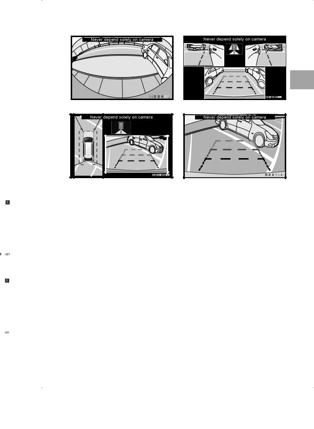
e Rear View Display Indications
<Rear Panorama View>
<Rear Top View> |
<Rear Mirror View> |
<Rear View> |
•With this system, the brightness and tint of each camera is automatically adjusted. When driving in areas where the brightness or tint varies widely, the brightness or tint of the camera image on the screen may become unstable.
•Depending on the condition of the car or road surface, the range of vision may vary. Refer to “About the Front Camera Image and Camera Guide” (page 7) or “About the Rear Camera Image and Camera Guide” (page 8).
5-EN
Camera Image
Image Patterns and Distance Guidelines
This camera system synthesises and combines four camera images, enabling you to select and switch to any image pattern. The distance guidelines displayed vary for each pattern. For details of how to switch image patterns, refer to “Camera Operation” (page 14).
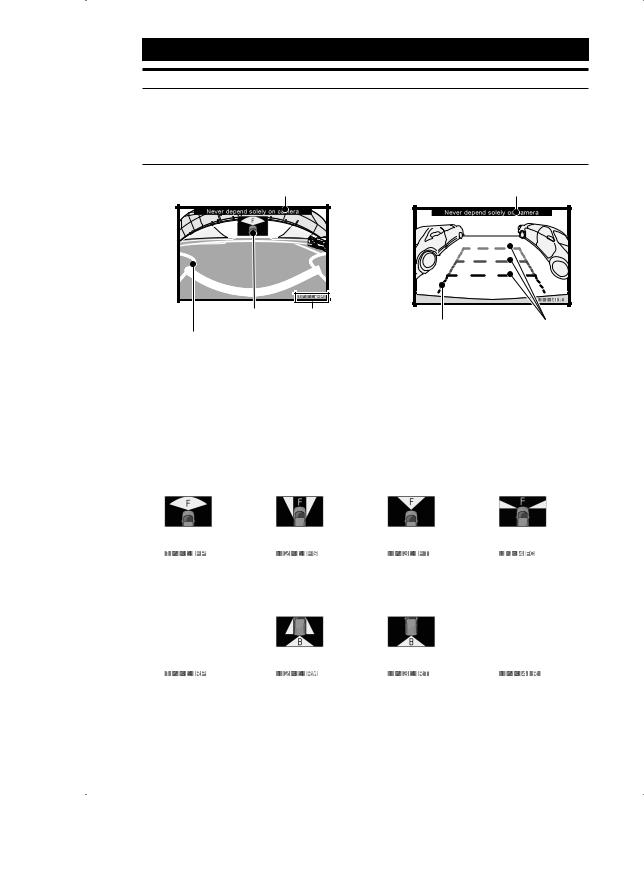
How to Interpret a Camera Image
<Front Panorama View> |
<Rear View> |
|||||||
|
Caution message *1 |
|
Caution message *1 |
|||||
|
|
|
|
|
|
|
|
|
|
|
|
|
|
|
|
|
|
|
|
|
|
|
|
|
|
|
|
|
|
|
|
|
|
|
|
|
|
|
|
|
|
|
|
|
A B
Camera Image Range
* Varies with image pattern
Vehicle width extension |
Distance guidelines |
marks |
* Vary with image pattern |
* Only displayed in the |
|
rear view image. |
|
*1 If no caution message is displayed, be sure to make the correct display settings. Have an authorized Alpine dealer perform the correct display settings in calibration mode.
A: Current image range
B: Current image pattern
<Front View Image> |
|
|
|
p Front Panorama |
p Front Side View |
p Front Top View |
p Front Corner View |
View |
|
|
|
A |
A |
A |
A |
B 1 FP |
B 2 FS |
B 3 FT |
B 4 FC |
<Rear View Image> |
|
|
|
p Rear Panorama |
p Rear Mirror View |
p Rear Top View |
p Rear View |
View |
|
|
|
A No icon |
A |
A |
A No icon |
B 1 RP |
B 2 RM |
B 3 RT |
B 4 R |
6-EN
 Loading...