


 Loading...
Alesis QuadraVerb Service Manual
Revision 1.00
6/28/94
Alesis QuadraVerb Service Manual------ |
1 |
PREFACE
This document is intended to assist the service technician in the operation, maintenance and repair of the QuadraVerb digital effects processor. Together with the QuadraVerb Reference Manual, this document provides a complete description of the functionality and serviceability of the QuadraVerb. Any comments or suggestions you may have pertaining to the document are welcome and encouraged.
READ THIS!
In addition to any purchase price that Alesis may charge as consideration for Alesis selling or otherwise transferring this service manual (“Manual”) to you, if you are not a service and repair facility (“Service Center”) authorized by Alesis in writing to be an authorized Service Center, Alesis sells or transfers the Manual to you on the following terms and conditions:
Only Service Centers authorized by Alesis in writing are authorized to perform service and repairs covered by an Alesis warranty (if any), and transfer of the Manual to you does not authorize you to be an authorized Service Center. Therefore, if you perform, or if the Manual is used to perform, any service or repairs on any Alesis product or part thereof, any and all warranties of Alesis as to that product and any service contract with Alesis for that product shall be voided and shall no longer apply for such product, even if your services or repairs were done in accordance with the Manual.
All service or repairs done by you or with reference to the Manual shall be solely your responsibility, and Alesis shall have no liability for any such repairs or service work. All such service or repairs are performed at the sole risk of the person performing the service or repairs. You agree that all such work will be performed in a competent, professional and safe manner at all times and to indemnify and fully hold Alesis and its successors and assigns harmless in the event of any failure to so perform.
Your purchase of the Manual shall be for your own ultimate use and shall not be for purposes of resale or other transfer.
As the owner of the copyright to the Manual, Alesis does not give you the right to copy the Manual, and you agree not to copy the Manual without the written authorization of Alesis. Alesis has no obligation to provide to you any correction of, or supplement to, the Manual, or any new or superseding version thereof.
Alesis shall have the right to refuse to sell or otherwise transfer repair parts or materials to you in its sole discretion. You shall not use, sell or otherwise transfer spare or replacement parts supplied by Alesis to you (i) to repair or be used in products manufactured for or by third parties or (ii) to any third parties for any purpose.
You shall not make any warranties or guarantees with respect to the products of Alesis or the use thereof on behalf of Alesis or in your own name.
The foregoing describes the entire understanding related to sale or transfer of the Manual to you, and no other terms shall apply unless in a writing signed by an authorized representative of Alesis.
Alesis QuadraVerb Service Manual------ |
2 |
WARNINGS
TO REDUCE THE RISK OF ELECTRIC SHOCK OR FIRE, DO NOT EXPOSE THIS PRODUCT
TO WATER OR MOISTURE.
CAUTION
RISK OF ELECTRIC SHOCK
DO NOT OPEN
The arrowhead symbol on a lightning flash inside a triangle is intended to alert the user to the presence of un-insulated "dangerous voltage" within the enclosed product which may be of sufficient magnitude to constitute a risk of electric shock to persons.
The exclamation point inside a triangle is intended to alert the user to the presence of important operating, maintenance and servicing instructions in the literature which accompanies the product.
CAUTION
Danger of explosion if battery is incorrectly replaced. Replace only with the same type or equivalent type recommended by the equipment manufacturer. Battery Manufacturer: Tadiran
Type: TL-5101
Rating 3.6V
REPAIR BY ANY PERSON OR ENTITY OTHER THAN AN AUTHORIZED ALESIS SERVICE
CENTER WILL VOID THE ALESIS WARRANTY.
PROVISION OF THIS MANUAL DOES NOT AUTHORIZE THE RECIPIENT TO COMPETE WITH ANY ALESIS DISTRIBUTOR OR AUTHORIZED REPAIR SERVICE CENTER IN THE PROVISION OF REPAIR SERVICES OR TO BE OR MAKE REPAIRS AS AN AUTHORIZED SERVICE CENTER.
ALL REPAIRS DONE BY ANY ENTITY OTHER THAN AN AUTHORIZED ALESIS SERVICE CENTER SHALL BE SOLELY THE RESPONSIBILITY OF THAT ENTITY, AND ALESIS SHALL HAVE NO LIABILITY TO THAT ENTITY OR TO ANY OTHER PARTY FOR ANY REPAIRS BY THAT ENTITY.
Alesis QuadraVerb Service Manual------ |
3 |
SAFETY SUGGESTIONS
Carefully read the applicable items of the operating instructions and these safety suggestions before using this product. Use extra care to follow the warnings written on the product itself and in the operating instructions. Keep the operating instructions and safety suggestions for reference in the future.
1.Power Source. The product should only be connected to a power supply which is described either in the operating instructions or in markings on the product.
2.Power Cord Protection. AC power supply cords should be placed such that no one is likely to step on the cords and such that nothing will be placed on or against them.
3.Grounding the Plug. This product has a 3-wire grounding type of plug (a plug with a grounding pin) for safety purposes. This plug can only be used in a grounding power outlet. If the plug does not insert into the outlet you are using, the outlet probably is not a grounding type of power outlet. Contact your electrician to replace the obsolete outlet with a grounding type of outlet instead of defeating the safety feature of the grounding type of plug.
4.Periods of Non-use. If the product is not used for any significant period of time, the product's AC power supply cord should be unplugged from the AC outlet.
5.Foreign Objects and Liquids. Take care not to allow liquids to spill or objects to fall into any openings of the product.
6.Water or Moisture. The product should not be used near any water or in moisture.
7.Heat. Do not place the product near heat sources such as stoves, heat registers, radiators or other heat producing equipment.
8.Ventilation. When installing the product, make sure that the product has adequate ventilation. Improperly ventilating the product may cause overheating, which may damage the product.
9.Mounting. The product should only be used with a rack which the manufacturer recommends. The combination of the product and rack should be moved carefully. Quick movements, excessive force or uneven surfaces may overturn the combination which may damage the product and rack combination.
10.Cleaning. The product should only be cleaned as the manufacturer recommends.
11.Service. The user should only attempt the limited service or upkeep specifically described in the operating instructions for the user. For any other service required, the product should be taken to an authorized service center as described in the operating instructions.
12.Damage to the Product. Qualified service personnel should service the unit in certain situations including without limitation when:
a.Liquid has spilled or objects have fallen into the product,
b.The product is exposed to water or excessive moisture,
c.The AC power supply plug or cord is damaged,
d.The product shows an inappropriate change in performance or does not operate normally, or
e.The enclosure of the product has been damaged.
Alesis QuadraVerb Service Manual------ |
4 |
General Troubleshooting
While this manual assumes that the reader has a fundamental understanding of electronics and basic troubleshooting techniques, a review of some of the techniques used by our staff may help.
1.Visual Inspection - A short visual inspection of the unit under test will often yield results without the need of complex signal analysis (burnt, or loose components are a dead giveaway).
2.Self Test - Alesis products that utilize microprocessor control contain built in test software which exercises many of the units' primary circuit functions. Self test should always be done following any repair to ensure basic functionality.
3.Environmental Testing - Applying heat and cold (heat gun/freeze spray) will often reveal thermally intermittent components (Clock crystals, I.C.s, and capacitors are particularly prone to this type of failure).
4.Burn in Testing - Leaving a unit running overnight often reveals intermittent failures such as capacitors that begin to leak excess current after a significant amount of time.
5.Cable Checks - Wiggling cables can reveal intermittent failures such as loose cables or poorly soldered headers. Remember to check power supply cables as well.
6.Flexing the PC Board - Poor solder joints and broken traces can often be found by pressing the PC Board in various places.
7.Tapping Componants - Somtimes tapping on a component (particularly crystals) will cause it to fail.
8.Power Down/up - Turning the unit off and back on rapidly several times may reveal odd reset and/or power supply failures.
9.Reset Threshold - A Variac (variable transformer) can be used to check reset threshold levels. This can be particularly useful in helping customers with low line problems.
10.Compressors - Using a compressor/limiter is often helpful when attempting to solve low level noise problems, as well as assisting with DAC adjustments.
11.Sweep Tests - Sweep generators are very useful in checking the frequency response envelopes of antialiasing filters.
12.Piggybacking - Piggybacking I.C.s is particularly useful when troubleshooting large sections of logic. This is especially true when working with older units.
Alesis QuadraVerb Service Manual------ |
5 |
|
Table of Contents |
|
PREFACE .................................................................................................................................... |
|
ii |
READ THIS! ................................................................................................................................. |
ii |
|
WARNINGS................................................................................................................................. |
iii |
|
SAFETY SUGGESTIONS ........................................................................................................... |
iv |
|
General Troubleshooting.............................................................................................................. |
v |
|
1.0 QuadraVerb General Description ........................................................................................... |
1 |
|
2.0 Power Supply ......................................................................................................................... |
1 |
|
2.1 |
Battery Backup .......................................................................................................... |
2 |
3.0 Analog Signal Paths ............................................................................................................... |
2 |
|
3.1 |
Anti-Aliasing Filters.................................................................................................... |
3 |
3.2 |
Successive Approximation ........................................................................................ |
3 |
4.0 Digital Signal Paths ................................................................................................................ |
4 |
|
4.1 |
80C31 Micro Controller Circuit .................................................................................. |
4 |
4.2 |
Reset ......................................................................................................................... |
4 |
4.3 Memory Mapped I/O.................................................................................................. |
5 |
|
4.4 |
Analog Input and the 8031 ........................................................................................ |
5 |
4.5 DASP 24 ASIC .......................................................................................................... |
5 |
|
5.0 Test Procedures ..................................................................................................................... |
6 |
|
6.0 Adjustments............................................................................................................................ |
6 |
|
7.0 Updates and Revisions .......................................................................................................... |
6 |
|
7.1 |
D15............................................................................................................................ |
7 |
7.2 |
Header Capacitor ...................................................................................................... |
7 |
7.3 |
R66............................................................................................................................ |
7 |
7.4 SRAM Supply ............................................................................................................ |
7 |
|
7.5 |
Battery Ground .......................................................................................................... |
7 |
7.6 |
Cables ....................................................................................................................... |
7 |
7.5 |
LCD Contrast............................................................................................................. |
7 |
7.6 |
LCD Cable Header .................................................................................................... |
7 |
7.7 Wet VCA Removal .................................................................................................... |
7 |
|
7.8 |
DAC Adjustment Installation...................................................................................... |
8 |
7.9 |
Increasing Output Gain ............................................................................................. |
8 |
7.10 QV I/P Filter Kit Installation ..................................................................................... |
8 |
|
8.0 Helpful Hints & Common Solutions ........................................................................................ |
12 |
|
9.0 Schematics............................................................................................................................. |
14 |
|
10.0 Software History ................................................................................................................... |
16 |
|
11.0 Quadraverb Plus MIDI Implementation/System Exclusive ................................................... |
18 |
|
12.0 Quadraverb Service Parts List ............................................................................................. |
34 |
|
Index............................................................................................................................................. |
|
37 |
Service Manual History................................................................................................................. |
39 |
|
Alesis QuadraVerb Service Manual------ |
6 |
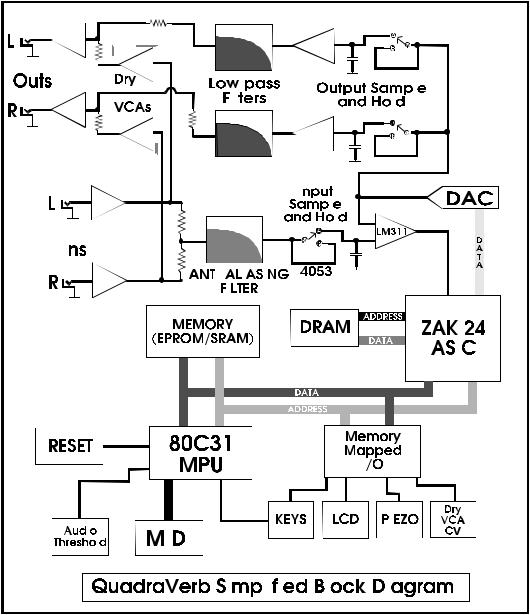
1.0 QuadraVerb General Description
The QuadraVerb, and other digital reverbs, achieve their results by slicing analog signals into segments, and then converting them to a numeric value, corresponding to the amplitude of the signal at that particular instant. These values are then mathematically manipulated, and stored at various locations in a memory "loop" for eventual playback. By varying the placement and amplitude of incoming samples, discrete time delays are achieved. When mixed together, and converted back into analog, these delays simulate the reflections associated with natural reverbs, and delays, as well as non natural
effects such as reverse reverbs, and gated reverbs. The added capabilities of an 80C31 micro controller allow for user manipulation and storage of algorithm
parameters, as well as effects such as chorus, and flange, that require real-time manipulation of algorithms. Please note that there are
several different main
PCB revisions, so differences will be noticed from unit to
unit.
2.0 Power Supply
The power
supply begins with the 9 Volt A.C., adapter. Input from J6 is R.F.
filtered by C31 before on/off switch S1. From
there it is split for the +12V, -12V, and +5V
rails. The +12V rail consists of a voltage
doubler (C22, C24, and D13, D14), a 7812 regulator (U31), and filter caps (C3, C14). The -12V rail is a "mirror" of the +12V rail, consisting of voltage doubler (C21, C23, and D10, D11), a 7912 regulator, and filter capacitors (C7, and C15). The +5V rail consists of a rectifier diode (D12), filter capacitors (C17-C20), a 7805 regulator, and a multitude of 0.1uF bypass capacitors. Note that the raw +10V line used by the microprocessor reset, and the SRAM power supply (when retrofitted), and is located at the input to the 7805 regulator.
2.1 Battery Backup
Alesis QuadraVerb Service Manual------
Battery backup is actually more complicated than it might first appear, as it depends on a good system reset (see section 4.2 for details) in order to function properly. The actual backup circuit consists of a battery (3V - 3.6V Lithium), a 10K resistor (R61) for checking standby current (see below), a "steering" diode (D4), a filter capacitor (C16), and a transistor/resistor/diode combination that acts as a steering diode. This combination may be missing on older board revisions, and must be installed (see section 7.0) to prevent data corruption due to a significant difference between Vcc, and the amplitude of the data buss.
SRAM standby current should always be checked. While the unit is off, check the voltage across R61. If the voltage is higher than 80mV (specification, although a 1 to 20mV range is more normal) then a problem exists. Usually it indicates a bad (or simply wrong) SRAM, or a short, somewhere along the MEM PWR line. Note, that for a short time, Sony 58256-PM (high power) SRAMs were being installed at the factory, and should be replaced with low power versions (58256LP) when found (see section 7.0.), in order to eliminate excess battery drain. We are currently using Hitachi 62256ALPs as replacements.
CAUTION:Danger of explosion if battery is incorrectly replaced. Replace only with the same type or equivalent type recommended by the equipment manufacturer.
Battery Manufacturer: Tadiran Type: TL-5101
Rating 3.6V
3.0 Analog Signal Paths
The inputs (stereo) have their impedances fixed at 1M by R3 and R6. While operating the unit monauraly (left input only) the input impedance fixed at 500K (R3, and R6, in parallel). From there, the inputs are buffered by U1, A.C. coupled (C1, C2), and passed through a variable (input level), X10, gain stage. The stereo signal is then sent to the outputs via the dry VCA (U5). It is also summed to mono (Via R17, R18) before being passed along to the anti-aliasing filter (discussed later), and the LED control circuit. The LED circuit consists of a rectifier (U4, D2), a fairly standard comparator ladder (U7 & associated resistors), and a one shot multivibrator (U24, D3, etc.) to provide a time constant so that ASIC math overflow conditions stay highly visible.
The summed stereo signal, after passing through the anti-aliasing filter, continues into the input sample and hold circuit. The input sample and hold circuit consists of 1/3 of the 4053 analog switch (U9), the input sample cap (C38), a buffer amplifier (U3), and a comparator (U8).
The signal beyond this point is purely digital, until the DAC output cycle of the DASP 24. At the appropriate time, the DAC will output the processed left, and right signals. This action is coordinated with the two output sample and hold circuits (2/3 U9, 2 op amps of U3, C39, C40), so that each receives the correct, separate signal for stereo output. After passing through low pass filters (2 op amps of U4, Misc. Resistors & Capacitors), the signals are summed with the output of the dry VCAs (note that on older board revisions, the signal will pass through the wet VCA [U6] first). The signals then pass through another filter section (U2, etc.), to the output potentiometer. From here, they pass through unity gain amps (U2, etc.), and finally through impedance fixing resistors R9, and R14, to the output jacks. Note that some incompatibilities have been encountered when using the QuadraVerb with some particular amplifier effects loops. If the customer is experiencing level drops when using the unit in such a setup, it is possible to adjust the output stage gain to accommodate the amplifier (see section 7.11).
Alesis QuadraVerb Service Manual------

3.1 Anti-Aliasing Filters
Different QuadraVerb PCB revisions utilize 3 different types anti-aliasing filters, to eliminate Nyquist errors. The 1st
is a four pole active filter, and will be seen on the oldest PCB revisions (A through E). If problems occur when using these older board revisions with digital synth's, and some "hot"
guitar pickups, it will be necessary to upgrade this filter to a type 2. The type 2 filter is a
six pole version of the active filter, and includes a preemphasis curve. It will only be
seen on older board rev.s that have been upgraded. The 3rd type of filter is the LC block filter. This single component filter is seen on revision F, and later, boards. It eliminates the need for
active circuitry, as well as facilitating easier servicing.
3.2 Successive Approximation
Successive approximation is a heuristic approach to the process of analog to digital conversion. The idea is to divide the process into short, manageable sections. Each significant binary weight (starting
with the Most Significant Bit) is taken in turn, thus requiring only 16 comparisons to achieve a final value.
The process begins with the input "sample and hold circuit". 1/3 of the 4053 (U9) is turned on, allowing the input sample capacitor (C38) to charge [or discharge] to the level of the current input signal. When the switch is turned off, the capacitor will hold that level indefinitely
[barring internal leakage ]. At this point, the SAR (Successive Approximation Register-part of the DASP 24 ASIC) will take over. Starting with the MSB, the SAR will set the bit, and compare the output of the DAC, to the level of the input sample capacitor (via comparator U8). The results of the
Alesis QuadraVerb Service Manual------
comparison are stored, and the next most significant bit is compared. This process continues until a value is found for all 16 bits, and the data is ready for further processing by the ASIC (note that the value is in two's compliment math). In order to view these signals properly on the scope, it will be necessary to use an external scope sync (use U9, pin 9 as the sync source). Diagrams 2, and 3, show the DAC output during a couple of SAR cycles, with no input, and full input.
4.0 Digital Signal Paths
Note that later board revisions incorporate a "split" data buss. In other words, most "external" data lines are separated from the main buss via a de coupling network (R35, R84-90, C28-30, C3537, C42, C44). This is to provide better RF suppression, however, it can also cause some unique situations. Normal signals on this "secondary" buss, will appear extremely distorted (for digital signals), and sometimes lead a technician to believe that there may be a bad latch, even though all components on the buss are functioning properly. Conversely, a bad latch can load the buss in such a way, that bad timing occurs, corrupting data even though the signals appear "normal".
4.1 80C31 Micro Controller Circuit
The 80C31 MPU controls all "user interface" functions of the QuadraVerb. These functions range from handling the front panel buttons, to continuously updating algorithm information to the DASP 24 ASIC. Note that the 8031 data buss serves a dual purpose. This buss multiplexes between low order addresses (1st 8 bits), and data. Latch U20 is used to hold the low order address half, during 8031 read and write cycles. The EPROM (U19) is used to hold both program information, and algorithm data. The SRAM (U18) holds system variables, as well as user preset data. The 12MHz 8031 clock is derived from the 24MHz clock (Z1) via a divide by 2 counter (1/2 U24). MIDI I/O is handled through the 8031's built in RXD (Read Serial Data), and TXD (Transmit Serial Data) ports. Front panel keypad decoding is handled through a combination of memory mapped I/O (see section 4.3), and the 8031's built in I/O ports.
4.2 Reset
The 8031 reset circuit is perhaps the single most important circuit in the QuadraVerb. When this circuit is functioning incorrectly, problems ranging from loss of battery backup, to a complete lock-up of the machine, can occur. A thorough knowledge of the operation of this circuit will greatly facilitate troubleshooting this unit.
This circuit uses the differential between raw +10V, and regulated +5V, to generate the required signals for system reset. This is necessary due to fact that the system MUST be in a reset state while powering down, otherwise, random noise on the 8031 data, and address, busses could corrupt SRAM data, and destroy any hope that the battery backup will work. C25 acts as a long time constant, to ensure that reset line is enabled long enough for proper system reset. D7 acts as a quick discharge path for C25, ensuring that resets will occur, even if the unit is turned off, and then rapidly back on. R16, R60, R58, and D15, work together as a voltage divider to the base of Q3, and is designed so that transistor Q3 will turn on when the raw +10V supply is roughly 7V. This is to ensure that reset does not occur until after the +5V regulator is fully functioning (i.e. +5V rail is solid). If reset occurs too early, noise on the +5V rail can cause data corruption. Pull-up resistor R59 holds the input of the inverter (U25, pins 13, 12) high, until Q3 turns on, pulling the input low. When this occurs, the output of 2nd inverter (U25 pins 10, 11) will also go low, slowly, due to the time constant of R95, and C32. The power off reset is similar. When the +10V raw supply sinks below 7V, Q3 is turned off, allowing the input of the inverter (U25, pins 13,12) to pull high (via pull-up R59), and thus the same for the output of the 2nd inverter (U25, pins 10,11). Also note the tap between the two inverters, running to the input of AND gate U26 (pins 1,2, and 3). This prevents access to SRAM functions while in the reset condition, thus preventing data corruption.
Alesis QuadraVerb Service Manual------
4.3 Memory Mapped I/O
The QuadraVerb (and many other Alesis products) utilizes a memory mapped I/O system in order to deal with the wide variety of functions that the 8031 needs to access. During the write cycle of the 8031, data on the 8031 data buss is made available to a series of latches. When the WRN (pin 16) signal of the 8031 is enabled, and A15 (address's most significant bit) is active, the 3 to 8 line demux (U23) is used to decode the 3 least significant address lines, and send a strobe to the clock input of one of these latches. Consequently, data can be "stored" into a latch simply by writing a value into a memory location. Note that, in this scenario, data is write only. All input functions to the 8031 are handled through the 8031's built in I/O ports.
4.4 Analog Input and the 8031
While output from the 8031 can be handled simply using memory mapped I/O, and binary weighted networks, analog input to the 8031 is a bit trickier. The method used in the QuadraVerb, is to examine the time it takes a constantly charging capacitor to reach the level of the input signal. The majority of op amp U22 is used to accomplish this. We will examine the audio threshold input. The principle will also apply to the piezo (Z2) value input circuit.
The process begins with the 8031 temporarily turning on Q2 (via mapped I/O latch U29). After turning Q2 back off, the 8031 begins counting. While the 8031 is counting, C56 charges through R51. This signal is compared to the incoming rectified analog signal (from the LED control circuit) by U22 (pins 5, 6, and 7). When the charge on C56 reaches the level of the input signal, U22 pin 7 will change states, informing the 8031 via input port P3.2. The 8031 ceases counting, and can use the "count" value as a "level" value for processing.
4.5 DASP 24 ASIC
The DASP (Digital Audio Signal Processor) 24 ASIC (Application Specific Integrated Circuit), is a complex, VLSI IC designed specifically to handle the specialized needs of digital effects processing. Obviously, a full discussion of this device is beyond the scope of this manual, however, a brief introduction to the device is definitely in order.
The DASP 24 contains a SAR (Successive Approximation Register), a writable control store (internal memory for algorithm storage), and a RISC (Reduced Instruction Set Computer) for use as an Arithmetic Logic Unit. Memory management hardware, and a variety of control hardware round out the package. Some important control signals are outlined below.
Alesis QuadraVerb Service Manual------

Signal |
Pin |
Function |
|
|
|
|
|
|
RAS |
3 |
- DRAM Row Address Strobe |
|
|
|
CAS |
4 |
- DRAM Column Address Strobe |
|
|
|
MDE |
5 |
-DRAM output enable. |
|
|
|
STB |
40 |
- Instructs DASP 24 to accept 8031 DATA |
|
|
|
CLK |
42 |
- 24MHz clock from Z1 |
|
|
|
RST |
53 |
- RESET |
|
|
|
INH |
54 |
- Controls sample and hold circuit timing. |
|
|
|
SNHOUT 0 |
55 |
" |
|
|
|
SNHOUT 1 |
56 |
" |
|
|
|
LSTMSB |
57 |
- This signal indicates the last state of the MSB (the sign bit in two's complement math). This |
signal, in conjunction with R36, R47, R48, and C13, is used to bias the incoming analog signal slightly positive, or negative, depending on the result of the last DAC cycle (i.e. if the last DAC cycle started off with a negative value, LSTMSB will be 1, causing the input to the sample and hold circuit to pull slightly positive. On the next cycle, the reverse will occur). This reduces any audio pop during the attack portion of the input signal, and allows for a faster response to small signals.
ADC |
74 |
- A/D comparison input. |
|
|
|
OVFLO |
75 |
- This signal indicates a math overflow condition, and consequently turns on the clip LED circuit. |
|
|
|
WR |
84 |
- DRAM write enable |
5.0 Test Procedures
If possible, user data should be saved (a DataDisk is recommended) prior to any servicing. This, of course, may not always be possible (i.e. dead power supply, bad reset signal, corrupt data, etc.). Saving user data may also be accomplished after unit functionality is restored (i.e. power supply, or reset line, is repaired), and prior to further servicing, and testing. The unit should always be reinitialized (power unit up while holding "BYPASS" and "PROG" buttons down) after changing the EPROM, SRAM, or any part of the battery backup. To perform the QuadraVerb's self diagnostics connect a MIDI cable between MIDI in, and MIDI out. Power up the unit while holding the "BYPASS", and "CONFIG", buttons down. The unit will then test ROM, RAM, Button LEDs, MIDI, and the clip LED. In the event of a ROM, RAM, or MIDI failure, the unit will stop, and the display will show "ERROR IN {COMPONENT}".
6.0 Adjustments
There are no adjustments necessary, unless a DAC adjust trimpot has been installed at the time of service. The easiest way to adjust the DAC is to use a fast lezlie program, with no signal input. With the lezlie output turned fully up, adjust the trimpot for a minimum noise floor. (See section 7.0 for installation instructions.)
7.0 Updates and Revisions
Note that these items may not apply to all board revisions. Where updates are board revision specific, the bold type characters at the beginning of the note indicates applicable board revision designations.
7.1 D15
A-E Zener diode (D15) at bottom, right-hand corner of board (in reset circuit) should be a metal zener and NOT a glass zener. The glass types have been found to be somewhat unreliable.
Alesis QuadraVerb Service Manual------
7.2 Header Capacitor
A-E There should be a .1uF cap added between pins 1 and 3 of LED cable header J2. This prevents possible oscillation at power up.
7.3 R66
R66, next to opto isolator (U30), should be 10K. If it is 47K, add a 12K or 13K resistor in parallel to make it 10K. This decreases the opto-isolators input threshold, for improved MIDI input performance.
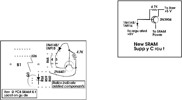
7.4 SRAM Supply
SRAM Supply adjustment (See diagrams 4 and 5). This supplies a solid 5V to the SRAM, preventing input data from being higher in amplitude than the supply voltage, which can cause data corruption.
Diagram 4
7.5 Battery Ground
Check battery GND connection and resolder if necessary. Cold solder joints, can exist there, resulting in memory loss and crashing.
|
7.6 Cables |
|
Check all connector cables are firmly seated. |
Diagram 5 |
In some cases, they can come 1/2 way off. |
7.5 LCD Contrast
Check LCD contrast - if contrast is too dark then short D6.
7.6 LCD Cable Header
Hot glue the LCD cable header to LCD, to prevent it from falling off in transit.
7.7 Wet VCA Removal
A-E Software version 1.07 or above It may be necessary to bypass the wet VCA to decrease the noise floor. To do this, remove U6. Add jumpers across C11, C12, from U6 pin 1 to pin 3, and from pin 5 to pin 7 (see diagram 7).*
Alesis QuadraVerb Service Manual------

7.8 DAC Adjustment Installation
It may also be necessary to install a DAC adjust trimpot to decrease DAC noise. The components required are a 250K trimpot (R43), 2 200K resistors (R20 and R44), and a 1M resistor (R45). See diagram 8 for locations.*
7.9 Increasing Output Gain
It may be necessary to change the gain of the output stage to accommodate the users of some amplifier effects loops. To do this, change R11, and R12, to a value between 4.7K and 10K (the larger the value, the higher the gain).*
* - The application of these items are left to the discretion of the technician.
7.10 QV I/P Filter Kit Installation
The following update enhances the input filter of the Quadraverb by increasing the number of filter poles from 4 to 6. This gives a corresponding increase in the filter rolloff rate, and eliminates problems encountered when using the QV with high bandwidth samplers such as the Ensoniq ESQ- 1, the Roland D-50, or the EMU Proteus.
Here is a list of components that will be changed or added:
Component |
New Value |
Added |
Diagram |
* R16 |
9.1K |
------- |
7 |
R19 |
4.3K |
------- |
7 |
R23 |
680R |
------- |
7 |
R24 |
2.4K |
------- |
7 |
R25 |
27K |
------- |
7 |
* R26 |
33K |
------- |
7 |
* RA |
------- |
3.6K |
7 |
* RB |
------- |
1.3K |
7 |
R42a |
------- |
750R |
8 |
C35 |
47pF |
------- |
7 |
C36 |
.033uF |
------- |
7 |
C42 |
1500pF |
------- |
7 |
C43 |
.033uF |
------- |
7 |
C44 |
100pF |
------- |
7 |
* CA |
------- |
3300pF |
7 |
* CB |
------- |
.01uF |
7 |
**R20 |
------- |
200K |
8 |
**R44 |
------- |
200K |
8 |
**R45 |
------- |
1M |
8 |
**R43 |
------- |
250Ktrm |
8 |
* Requires special installation, see below. |
|
|
|
** Recommended, but not necessary. |
|
|
|
Alesis QuadraVerb Service Manual------
Loading...