


ALESIS
Wedge
Reference Manual

Introduction
Thank you for purchasing the Alesis Wedge Desktop Master Reverb Processor. To take full advantage of the Wedge’s functions, and to enjoy long and trouble-free use, please read this user’s manual carefully.
How To Use This Manual
This manual is divided into the following sections describing the various modes of the Wedge. Though we recommend you take time to read through the entire manual once carefully, those having general knowledge about effects devices should use the table of contents to reference specific functions.
Chapter 1: Your First Session with the Wedge. A basic introduction to getting the unit up and running, auditioning the factory Programs, adjusting levels, comparing and storing edited Programs.
Chapter 2: Connections. Deals with the necessary preparation before using, including connections to other components, such as instruments, mixing consoles, patchbays, and multitrack recorders.
Chapter 3: Description of Controls. A “dictionary” of all buttons, connectors, and Utility parameters. Use this chapter as a quick reference guide when searching for specific information.
Chapter 4: Editing Programs. A guided tour for programming typical single and multi-effect applications.
Chapter 5: Overview of Effects. A detailed look at the signal processing capabilities of the Wedge and the concept of reverb and effects programming. Includes descriptions of each parameter in the Wedge.
Chapter 6: MIDI Applications. This chapter discusses the various MIDI functions, such as recalling Programs, realtime modulation of parameters, and Sysex data transfer.
Chapter 7: Trouble-Shooting. Contains the Trouble-shooting Index, maintenance and service information, and MIDI implementation chart.
Appendices. MIDI basics, trouble-shooting, maintenance and service information, MIDI Implementation Chart and an Index.
Conventions
The buttons, knobs, and rear panel connectors are referred to in this manual just as their names appear on the Wedge, using all capital letters and in brackets (Example: [PROG] button, [VALUE] Knob, etc.). When text in the Wedge’s display is quoted, it is indicated using special typeface (Example: 00 to127, DELAY}REVERB, etc.).
JWhen something important appears in the manual, an icon (like the one on the left) will appear in the left margin. This symbol indicates vital information when operating the Wedge.
Wedge Reference Manual |
1 |

2 |
Wedge Reference Manual |

Wedge Reference Manual |
3 |

Contents
CONTENTS |
|
Your First Session with the Wedge............................................ |
7 |
Unpacking and Inspection .................................................................................................. |
7 |
Basic Connections................................................................................................................ |
7 |
Powering Up ........................................................................................................................ |
8 |
Dry Defeat............................................................................................................................ |
8 |
Setting Levels ....................................................................................................................... |
8 |
Automatic Input Level Settings ............................................................................ |
9 |
What’s in the Display? ........................................................................................................ |
10 |
Auditioning Internal Programs .......................................................................................... |
10 |
Switching Between Preset and User Banks.......................................................... |
10 |
Changing Effect Settings ..................................................................................................... |
11 |
Using Online Help ................................................................................................. |
12 |
Adjusting Effects Mix Levels ................................................................................ |
13 |
Comparing an Edited Program to its Original Settings ................................................... |
13 |
Restoring an Edited Program to its Original Settings ...................................................... |
14 |
Bypassing Effects ................................................................................................................. |
14 |
Storing and Naming Edited Programs .............................................................................. |
15 |
Connections................................................................................. |
17 |
AC Power Hookup .............................................................................................................. |
17 |
Line Conditioners and Protectors......................................................................... |
17 |
Audio Connections.............................................................................................................. |
17 |
Typical Applications.............................................................................................. |
18 |
Input Jack Wiring................................................................................................... |
18 |
Balanced Operation.................................................................................. |
19 |
Interfacing Directly with Instruments.................................................................. |
19 |
Using the Aux Sends................................................................................ |
21 |
Using Inserts ............................................................................................. |
23 |
Using Main Outputs................................................................................. |
24 |
Avoiding Ground Loops ....................................................................................... |
24 |
MIDI Connections ............................................................................................................... |
25 |
Description of Controls................................................................ |
27 |
Front Panel ........................................................................................................................... |
27 |
LCD Display........................................................................................................... |
27 |
VALUE Knob ......................................................................................................... |
28 |
EDIT/PAGE Button............................................................................................... |
28 |
TAP/AUDITION Button....................................................................................... |
29 |
A/B/C/D (NAME/ESC/</>) Buttons............................................................... |
29 |
A/B/C/D Sliders................................................................................................... |
29 |
PROGram Button ................................................................................................... |
30 |
UTILity Button ....................................................................................................... |
30 |
I/O Button .............................................................................................................. |
32 |
STORE Button ........................................................................................................ |
33 |
COMPARE Button ................................................................................................. |
33 |
BYPASS Button ...................................................................................................... |
33 |
Rear Panel............................................................................................................................. |
34 |
4 |
Wedge Reference Manual |

|
Contents |
Power Switch.......................................................................................................... |
34 |
Power ...................................................................................................................... |
34 |
MIDI In ................................................................................................................... |
34 |
MIDI Out/Thru...................................................................................................... |
34 |
Input (Left & Right) ............................................................................................... |
34 |
Output (Left & Right) ............................................................................................ |
34 |
Editing Programs ......................................................................... |
35 |
Selecting A Configuration................................................................................................... |
35 |
Editing Effect Parameters ................................................................................................... |
36 |
Moving Through Pages ......................................................................................... |
37 |
Using the A/B/C/D Buttons................................................................................ |
37 |
Using Online Help ................................................................................................. |
37 |
Special Cases .......................................................................................................... |
37 |
Naming A Program ............................................................................................................. |
38 |
Tutorial: Gothic Hall ........................................................................................................... |
39 |
Overview of Effects ..................................................................... |
41 |
The Architecture of the Wedge .......................................................................................... |
41 |
What is a Configuration?....................................................................................... |
41 |
Single....................................................................................................................... |
41 |
Parallel .................................................................................................................... |
41 |
Dual Mono.............................................................................................................. |
41 |
Multi Chain............................................................................................................. |
41 |
Reverb Effects ...................................................................................................................... |
44 |
Large Hall ............................................................................................................... |
44 |
Hall Reverb............................................................................................................. |
44 |
Room Reverb.......................................................................................................... |
44 |
Chamber ................................................................................................................. |
44 |
Ambience................................................................................................................ |
44 |
Stereo Room ........................................................................................................... |
44 |
Large Plate.............................................................................................................. |
44 |
Plate......................................................................................................................... |
45 |
Nonlinear................................................................................................................ |
45 |
Reverb Parameters............................................................................................................... |
46 |
Decay ...................................................................................................................... |
46 |
Low Pass Filter ....................................................................................................... |
46 |
High Pass Filter/Low Shelf................................................................................... |
46 |
Bass Boost ............................................................................................................... |
46 |
Pre-delay................................................................................................................. |
47 |
Pre-delay Mix ......................................................................................................... |
47 |
Density.................................................................................................................... |
47 |
Diffusion ................................................................................................................. |
47 |
Frequency Damping – Low & High ..................................................................... |
48 |
ER: Early Reflections (Spread, Shape and Level) ................................................ |
48 |
Depth ...................................................................................................................... |
49 |
Width ...................................................................................................................... |
49 |
Reverberation Swirl ............................................................................................... |
49 |
Gating...................................................................................................................... |
49 |
Delay Effects ........................................................................................................................ |
50 |
Mono Delay ............................................................................................................ |
50 |
Delay:Delay ............................................................................................................ |
50 |
Wedge Reference Manual |
5 |

Contents
Ping Pong Delay..................................................................................................... |
50 |
MultiTap Delay ...................................................................................................... |
50 |
Setting Delay Time Using Tap Tempo.................................................... |
50 |
Delay Parameters................................................................................................................. |
51 |
Delay Time ............................................................................................................. |
51 |
Tap .......................................................................................................................... |
51 |
Feedback ................................................................................................................. |
51 |
Low Cut/High Cut ................................................................................................ |
51 |
Density.................................................................................................................... |
51 |
Rate/Depth............................................................................................................. |
51 |
Tremolo Rate/Depth ............................................................................................. |
52 |
Pan Rate/Depth ..................................................................................................... |
52 |
Pitch Effects.......................................................................................................................... |
53 |
Chorus/Flange ....................................................................................................... |
53 |
Quad Chorus .......................................................................................................... |
54 |
Quad Pitch Shifter.................................................................................................. |
54 |
Chorus:Chorus ....................................................................................................... |
54 |
Chorus..................................................................................................................... |
54 |
Lezlie....................................................................................................................... |
54 |
Pitch Parameters .................................................................................................................. |
55 |
Rate ......................................................................................................................... |
55 |
Depth ...................................................................................................................... |
55 |
Feedback ................................................................................................................. |
55 |
Thru Zero................................................................................................................ |
55 |
Low Pass Filter ....................................................................................................... |
55 |
Feedback Highpass and Lowpass Filters ............................................................. |
55 |
Predelay .................................................................................................................. |
55 |
Wave ....................................................................................................................... |
56 |
Triggered Flange .................................................................................................... |
56 |
Width ...................................................................................................................... |
57 |
Level........................................................................................................................ |
57 |
Motor, Speed, High Rotor Level........................................................................... |
57 |
Effect Parameters................................................................................................................. |
58 |
MIDI Applications......................................................................... |
65 |
MIDI Functions.................................................................................................................... |
65 |
MIDI Channel......................................................................................................... |
65 |
MIDI Thru .............................................................................................................. |
65 |
Receiving Program Changes ................................................................................. |
66 |
Program Change Table .......................................................................................... |
66 |
Sysex Storage.......................................................................................................... |
67 |
Realtime Modulation Functions ......................................................................................... |
67 |
Defining the Modulation Sources......................................................................... |
68 |
Modulation Parameters Index .............................................................................. |
69 |
Setting Modulation Amplitude............................................................................. |
70 |
Realtime Sysex Control.......................................................................................... |
71 |
About System Exclusive vs. Controller Messages .............................................. |
71 |
Troubleshooting........................................................................... |
73 |
Trouble-Shooting Index ...................................................................................................... |
73 |
Re-initializing....................................................................................................................... |
73 |
Checking the Software Version .......................................................................................... |
74 |
6 |
Wedge Reference Manual |

|
Contents |
Maintenance/Service .......................................................................................................... |
74 |
Cleaning.................................................................................................................. |
74 |
Refer All Services to Alesis ................................................................................... |
74 |
Obtaining Repair Service....................................................................................... |
74 |
MIDI Implementation Chart.......................................................... |
76 |
Specifications .............................................................................. |
77 |
Wedge Reference Manual |
7 |

Contents
(GFX: Front & Rear Panel Diagram)
8 |
Wedge Reference Manual |

Your First Session with the Wedge – Chapter 1
CHAPTER 1
YOUR FIRST SESSION WITH
THE WEDGE
Unpacking and Inspection
Your Wedge was packed carefully at the factory, and the shipping carton was designed to protect the unit during shipping. Please retain this container in the highly unlikely event that you need to return the Wedge for servicing.
The shipping carton should contain the following items:
•This instruction manual
•Alesis Wedge with the same serial number as shown on shipping carton
•Program Chart
•AC Power Supply Adapter
•Alesis warranty card
JIt is important to register your purchase; if you have not already filled out your warranty card and mailed it back to Alesis, please take the time to do so now.
Basic Connections
The Wedge is designed to accommodate a number of applications, whether you are connecting it with a mixing console or connecting an instrument directly into it. Briefly described here are the basic connections to get you up and running quickly. For more information on connections, please refer to Chapter 2.
•Mono In, Mono or Stereo Out: Connect a 1/4” phone cord to the [LEFT] INPUT of the Wedge from a mono source The [LEFT] INPUT is normalled to the [RIGHT] INPUT. This means if you just connect the [LEFT] INPUT, and leave the the [RIGHT] INPUT unplugged, the same signal will be sent to both Inputs. Connect another cable from the [LEFT] OUTPUT of the Wedge to an amplifier or mixer input. Additionally, you could connect a second cable to the [RIGHT] OUTPUT for use with a stereo amplification system, or two mixer inputs.
•Stereo: Connect two 1/4” phone cords to the [LEFT] & [RIGHT] INPUTS of the Wedge from a stereo source , and two 1/4” phone cords from the OUTPUTS of the Wedge to a stereo amplification system or two mixer inputs.
Wedge Reference Manual |
7 |
Chapter 1 – Your First Session with the Wedge
Powering Up
After making your connections, turn on the system’s power using this procedure:
Ê Before turning on the Wedge’s power, check the following items:
•Have all connections been made correctly?
•Are the volume controls of the amplifier or mixer turned down?
ËTurn on the [POWER] switch on the front panel of the Wedge.
Upon power-up, the display will briefly read “ALESIS WEDGE”, and will then display the last selected Program Number (00–127, PRESET or USER Bank), and the [PROG] button’s LED will be lit.
Ì Turn on the power of the amplifier/mixer, and adjust the volume.
Dry Defeat
When connecting the Wedge to a mixing console’s aux sends and returns, it is generally desirable to remove the direct (dry) signal from the outputs of the Wedge so that its output signal contains only the effected (wet) signal. The dry signal may then be combined at the mixing console with the returning wet signal. The Wedge’s Dry Defeat function removes the direct signal globally from all Programs simultaneously.
ÊPress [UTIL].
The [UTIL] button will light.
ËPress [EDIT] until page 1 is selected.
The display will read:
Dry Defeat
Ì Press [D] to toggle the Dry Defeat parameter ON or OFF.
When Dry Defeat is On, the Mix parameter of each effect (described later) will read “- - -” to indicate it cannot be edited (it is fixed at 100%). Exceptions: The
RealRoom −>Flange Configuration will have its Reverb Mix parameter disabled (set at 100%), but the Flange effect’s Mix will still be available for editing. The Lezlie- >Room configuration will have its Lezlie Mix disabled, but the Reverb Mix will be available for editing. For more information, see Chapter 2.
8 |
Wedge Reference Manual |

Your First Session with the Wedge – Chapter 1
Setting Levels
Proper setting of the input and output levels is crucial in order to achieve the maximum signal-to-noise ratio. As a good rule of thumb, it is usually best to set both input and output level controls at 90% of full. This will decrease the possibility of overload distortion and keep the amount of background noise to a minimum.
To manually set the Input and Output levels:
Ê Connect your audio source to the Wedge’s input(s), as described in Chapter 2. Ë Press the [I/O] button.
ÌFeed signal to the Wedge’s input(s). You can set the Left and Right Input and Output levels by moving the Value Sliders and Value Wheel. Your input signal should make the meters go as far to the right as possible without clipping.
Automatic Input Level Settings
The Wedge has the unique ability to automatically select the proper levels for the inputs based on the signal you are routing to it. In other words, you tell the it to autoadjust levels, and then feed it a signal (play your guitar or keyboard, or play back the tape); the Wedge does the rest.
To auto-adjust the input levels:
Ê Connect your audio source to the Wedge’s input(s), as described in Chapter 2.
Ë Press and hold the [I/O] button, then press [TAP/AUDITION].
Ì Feed signal to the Wedge’s input(s).
The Auto Input function will “listen” to the signal at its input(s) for about 5 seconds, and adjust the input levels for both channels. If the Wedge doesn’t detect any signal level at the input, the Input Level will remain at its previous setting.
Wedge Reference Manual |
9 |
Chapter 1 – Your First Session with the Wedge
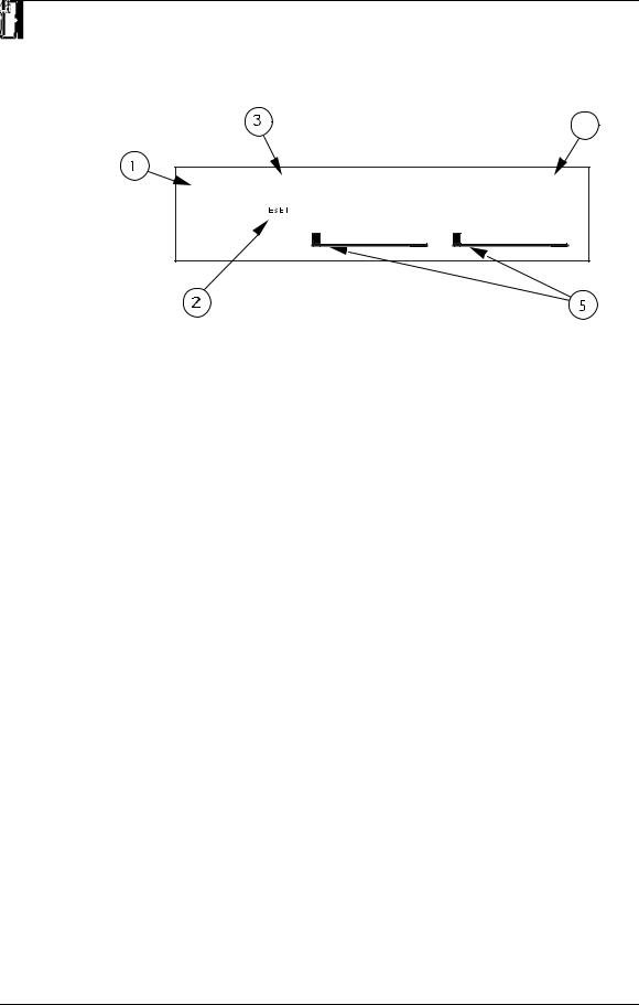
What’s in the Display?
When the Wedge is first turned on, the display will look something like this:
The Wedge’s display is divided into 5 sections:
Ê Program Number
Ë Preset/User Bank
Ì Program Name
Í Configuration
Î Input Level Meters
For more about the Wedge display, see Chapter 3.
Auditioning Internal Programs
The Wedge comes with 128 Programs in a Preset bank, plus another 128 Programs in the User bank. These Programs represent the wide range of applications for which the Wedge is suited.
To audition the internal effect Programs:
ÊPress the [PROG] button.
The [PROG] button will light.
Ë Turn the [VALUE] knob to scroll through the 128 Preset and 128 User Programs.
Switching Between Preset and User Banks
To instantly switch between the Preset and User banks, press the [PROG] button. Each time you press the [PROG] button, the Wedge will toggle back and forth between the Preset and User banks. The display will indicate this by reading either “PRESET” or “USER” next to the Program number.
You can also switch between banks when scrolling through the Programs with the [VALUE] knob. When you scroll clockwise past Preset 127, the display will “rollover” to User 00. Likewise, if you turn back the [VALUE] knob counterclockwise past User 00, the display will move to Preset 127. However, if you turn back the [VALUE]
10 |
Wedge Reference Manual |
Your First Session with the Wedge – Chapter 1
knob counterclockwise past Preset 00, the display will not wrap around back to User 127 but instead will remain at Preset 00.
Changing Effect Settings
When you dial up a Program, its Configuration is shown in the display to the right of the Program’s name. For example:
Vocal Ballad HALL REVERB
The Configuration will either be a single reverb type effect (as in the example above), or a combination of two or three effects (like Reverb+Delay, or Chorus>Delay> Reverb). Once you have identified what effects are used in the Program’s Configuration, you can then find the effect parameters more easily.
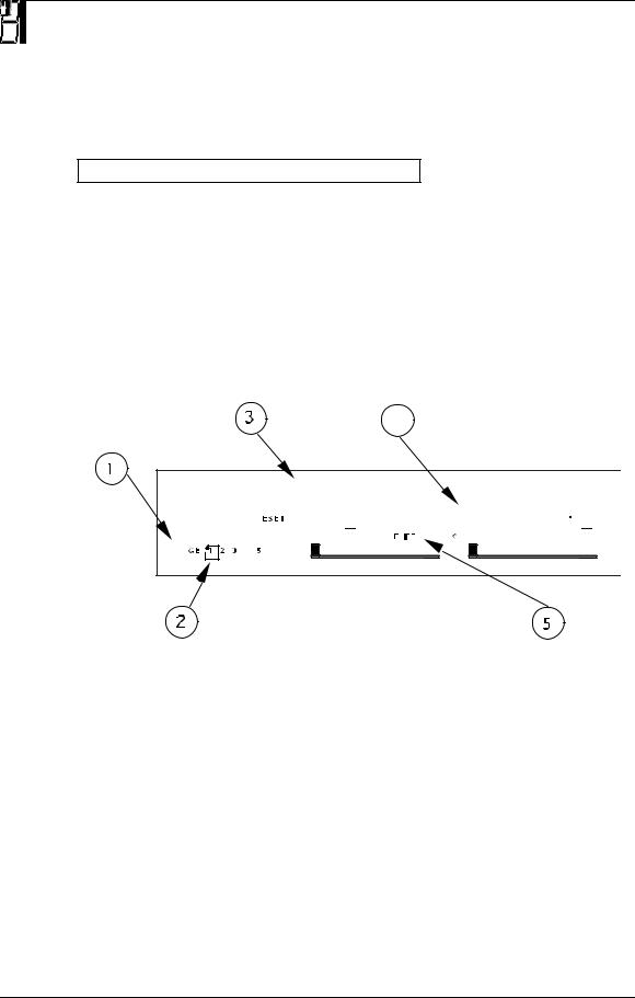
To edit a Program’s effect settings, you must first enter Edit mode. This is done by pressing either the [EDIT/PAGE] button or any one of the [A], [B], [C] or [D] buttons, as long as the [PROG] button is lit (Note: Pressing these buttons in other modes performs different functions). Once in Edit mode, the display will look something like this:
Ê Page Numbers
Ë Selected Page
Ì Parameter Name Strip
Í Parameter Values and Bar Graphs
Î A, B, C, D and EDITED Indicators
For more about using the Wedge Display in Edit mode, see Chapter 3.
Wedge Reference Manual |
11 |

Chapter 1 – Your First Session with the Wedge
To edit effect parameters:
ÊPress the [PAGE] button to enter Edit mode.
This selects the first page of effect parameters, if you are editing the Program for the first time. There are usually two or more pages available in Edit mode, depending on the Program’s Configuration. The exact number of pages available will be indicated by the numbers illuminated in the bottom-left corner of the display. Repeatedly pressing [PAGE] cycles through the available pages. The currently selected page will have a box around its number. Each page contains up to four parameters, which are labeled with abbreviated names directly above each.
ËMove one of the [A-D] sliders.
The parameter will flash indicating it is selected for editing. Once you have modified a parameter’s value, the word “EDITED” will appear directly beneath it. If you change the value back to its original setting, the word “EDITED” will disappear.
JAny changes you make are temporary, until you store those changes into memory. If the Program you are editing is in the Preset bank, you must save the changes you’ve made to a location in the User bank. If you recall another Program before storing, your changes will be lost. For more information , see “Storing Edited Programs”, later in this chapter. For more about editing effects parameters, see Chapter 4.
Using Online Help
The Wedge has built-in online help to assist you in identifying parameter functions from the display, without having to look things up in this manual. Once you have accessed Edit mode (see previous section), you can select any of the parameters shown in the display by pressing the corresponding button ([A], [B], [C] or [D]). However, by holding one of these buttons for more than one second, the upper display will provide a more detailed description of the selected parameter.
For example, if we were still editing Preset 18 (see previous page), holding the [D] button for more then one second would reveal the name of the “D” parameter:
INPUT LOWPASS FILTER
Once the button is released, the display reverts back to normal.
12 |
Wedge Reference Manual |

Your First Session with the Wedge – Chapter 1
Adjusting Effects Mix Levels
Whether a Program contains a single effect or two or three effects, you can adjust each effect’s mix to obtain a desirable balance between the original, uneffected signal and each effect’s output. The Mix parameter (or “wet/dry mix”) for each effect is found along with the other effect parameters in Edit mode. To make things easier, the Mix parameter has been consistently placed at the far right of the display page (this corresponds to the [D] button), on the last page of each effect. Since each effect has a different number of edit pages, the Mix parameter will not always appear on the same page for each Program. Keep in mind that if a Program uses more than one effect, each effect will have its own Mix parameter.
ÊPress the [EDIT/PAGE] button to enter Edit mode.
Look at the far right side of the display for the word MIX (or some variation that identifies a specific effect’s mix parameter; i.e. CMIX = Chorus Mix, RMIX = Reverb Mix, etc.). If it doesn’t appear, press the [PAGE] button repeatedly until you find it. To be sure the Mix parameter in the display is the one you want, use the built-in Online Help function (see previous section) by holding the [D] button for more than one second.
ËPress the [EDIT/PAGE] button repeatedly until you reach the highest numbered page available is selected.
ÌMove the [D] slider to edit the Mix parameter.
The parameter will flash indicating it is selected for editing. The Mix parameter’s range is 000-100å.
Comparing an Edited Program to its
Original Settings
The left side of the display always indicates the currently selected Program. If the [PROG] button is pressed once while in Edit mode, the currently selected Program’s name and the Configuration being used both appear in the upper part of the display.
Once a Program has been edited, the Configuration’s name will appear in lower case letters. With multi-effect Configurations (where there is more than one effect being used) and only one effect has been edited, only the edited effect’s name will appear in lower case letters. Example: If using the Configuration ROOM+DELAY and you have edited only the Delay’s parameters, the display will read “ROOM+delay” if the [PROG] button is pressed. This indicates that one or more of the Delay’s parameters have been altered, but the Reverb’s parameters have not been changed.
By pressing the [COMPARE] button, you can temporarily access the original version of the Program you are editing — that is, the last Program saved to the currently selected location number. This allows you to compare the differences created by changing parameters in the edited Program.
While you are in Compare mode, the display will show the previous values and the [COMPARE] button will light up. You can use the [EDIT/PAGE] button to scroll to other pages while in Compare mode. Pressing the button again or pressing [PROG]
Wedge Reference Manual |
13 |

Chapter 1 – Your First Session with the Wedge
exits Compare mode; the display will return to its original state and the edited version of the Program will be restored.
Restoring an Edited Program to its Original
Settings
If you decide to abort the changes you have made to an edited Program, this can be done in two easy steps:
ÊPress [PROG].
The display will exit Edit mode.
ËTurn the [VALUE] knob to select a different Program, then turn it back the opposite direction to re-select the original Program. (Alternately, you can press the [PROG] button three times.)
This recalls the stored version of the selected Program number, and the Configuration name in the display returns to all upper case letters. Consequently, any changes you had made to the Program before turning the [VALUE] knob would be lost. (That is, unless you stored the edited Program into memory first.)
Bypassing Effects
At any time you can bypass the effects, allowing you to hear the direct signal without any processing. This can be done by pressing the [BYPASS] button.
JIf the Dry Defeat function is on (see previous section) and the BYPASS button is pressed, no audio will pass through the unit. Similarly, if the Mix on any program is set to 100% wet and Bypass is pressed, the unit will not have any audio from its outputs.
14 |
Wedge Reference Manual |

Your First Session with the Wedge – Chapter 1
Storing and Naming Edited Programs
Once you are satisfied with the changes you have made to an edited Program, or are creating a new Program from scratch, you will need to store your edited Program back into memory. The Wedge will store the currently selected Program in nonvolatile memory (which is backed-up when the unit is turned off). If you edit a Program, the changes you made will still be there the next time you switch on the unit, even if you hadn’t stored the edited Program into memory yet. However, if you select another Program from memory before storing the edited Program, your changes will be lost forever.
JAlthough the Wedge has two banks (Preset and User), you can only store Programs in the User bank.
To store an edited Program:
ÊPress [STORE].
The [STORE] button will flash, and the display will read:
Store XXX (nnnnnnnnnnnn)?
…whereas XXX is a Program location number from 00—127 in the User bank, and
nnnnnnnnnnnn is the Program’s name.
ËUse the [VALUE] knob to select which location (00—127) you wish to store the selected Program into.
You can only store Programs into the User bank. If you select a Program from the Preset bank and store it, you will automatically be taken into the User bank.
ÌIf desired, change the Program’s name by pressing [A/NAME].
This moves the cursor from the location number field to the first character in the Program’s name. Turn the [VALUE] knob to scroll through the list of available characters. Use the [C/<] and [D/>] buttons to move the cursor’s position left and right, respectively. If you need to move the cursor back to the Program number field to select a different location to store to, press [B/ESC].
Note: To abort this operation — and thereby not store the edited Program — simply press any other button except [STORE].
ÍPress [STORE] again.
The [STORE] button’s LED will momentarily flash quickly, while the display reads:
Prog nnnnnnnnnnnn Stored!
…whereby nnnnnnnnnnnn is the Program’s name. The [STORE] button will turn off and the display will revert to wherever it was before [STORE] was pressed for the first time.
Wedge Reference Manual |
15 |

Chapter 1 – Your First Session with the Wedge
16 |
Wedge Reference Manual |

Connections – Chapter 2
CHAPTER 2
CONNECTIONS
AC Power Hookup
The Wedge comes with a power adapter suitable for the voltage of the country it is shipped to (either 110 or 220V, 50 or 60 Hz).
With the Wedge off, plug the round end of the supplied power adapter cord into Wedge’s [POWER] socket and the male (plug) end into a source of AC power. It’s good practice to not turn the Wedge on until all other cables are hooked up.
JAlesis cannot be responsible for problems caused by using the Wedge or any associated equipment with improper AC wiring.
Line Conditioners and Protectors
Although the Wedge is designed to tolerate typical voltage variations, in today’s world the voltage coming from the AC line may contain spikes or transients that can possibly stress your gear and, over time, cause a failure. There are three main ways to protect against this, listed in ascending order of cost and complexity:
•Line spike/surge protectors. Relatively inexpensive, these are designed to protect against strong surges and spikes, acting somewhat like fuses in that they need to be replaced if they’ve been hit by an extremely strong spike.
•Line filters. These generally combine spike/surge protection with filters that remove some line noise (dimmer hash, transients from other appliances, etc.).
•Uninterruptible power supply (UPS). This is the most sophisticated option. A UPS provides power even if the AC power line fails completely. Intended for computer applications, a UPS allows you to complete an orderly shutdown of a computer system in the event of a power outage, and the isolation it provides from the power line minimizes all forms of interference—spikes, noise, etc.
Audio Connections
The connections between the Wedge and your studio are your music’s lifeline, so use only high quality cables. These should be low-capacitance shielded cables with a stranded (not solid) internal conductor and a low-resistance shield. Although quality cables cost more, they do make a difference. Route cables to the Wedge correctly by observing the following precautions:
•Do not bundle audio cables with AC power cords.
•Avoid running audio cables near sources of electromagnetic interference such as transformers, monitors, computers, etc.
Wedge Reference Manual |
17 |
Chapter 2 – Connections
•Never unplug a cable by pulling on the wire itself. Always unplug by firmly grasping the body of the plug and pulling directly outward.
•Do not place cables where they can be stepped on. Stepping on a cable may not cause immediate damage, but it can compress the insulation between the center conductor and shield (degrading performance), or reduce the cable’s reliability.
•Avoid twisting the cable or having it make sharp, right angle turns.
•Although Alesis does not endorse any specific product, chemicals such as Tweek and Cramolin, when applied to electrical connectors, are claimed to improve the electrical contact between connectors.
Typical Applications
The audio inputs and outputs are typically used in one of three ways:
•from one or two aux send outputs of a mixer, and back to the effect return inputs of the mixer; or,
•from a line-level instrument (like a guitar or keyboard with either a mono or stereo output), and out to an amplifier or mixer input; or,
•from the stereo buss outputs of a mixer to a mix-down tape machine or amplifier.
When used with a mono source, the Wedge is placed between the source and the mixer/amplifier. Although the source may be mono, both the [LEFT] and [RIGHT] outputs can be connected to the inputs of a mixer/amplifier if stereo processing effects are desired.
Alternatively, you could use the inserts on your mixer to “patch in” only the left or right channel of the Wedge. If using the effect sends of a mixer, you have the advantage of sending any of the mixer’s input channels to the Wedge’s input(s), and have control over the level of each channel being sent.
These applications are outlined and illustrated in detail on the following pages.
Input Jack Wiring
The Wedge’s [LEFT] INPUT jack is normalled to the [RIGHT] INPUT. This means that if you only connect a single mono cable to the [LEFT] INPUT jack, it will also be routed to the [RIGHT] INPUT. However, if anything is connected to the [RIGHT] INPUT jack, this normalized connection will be broken; therefore the [LEFT] INPUT jack feeds only the [LEFT] INPUT, and the [RIGHT] INPUT jack feeds only the [RIGHT] INPUT.
18 |
Wedge Reference Manual |
Connections – Chapter 2
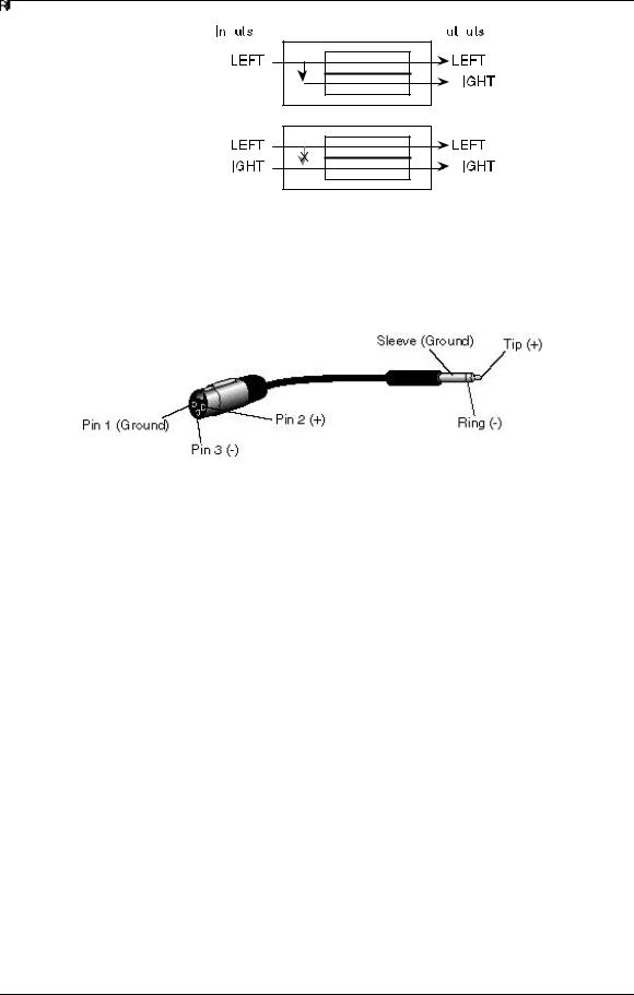
Balanced Operation
The Wedge features balanced TRS inputs and outputs. This allows it to be used with professional consoles and other balanced equipment. You may need to purchase an XLR to TRS 1/4” cable or adaptor, depending on the jacks used on the connecting equipment.
The Wedge uses Servo Balancing on its inputs. This means that you can plug in either a balanced (3-connector) or unbalanced (2-connector) signal without changing the input level setting.
Alternatively, if your console uses balanced 1/4” TRS connectors for the effects sends and returns (like the Alesis Studio 32) you should use “stereo phone cord” TRS balanced cables for connection to the Wedge.
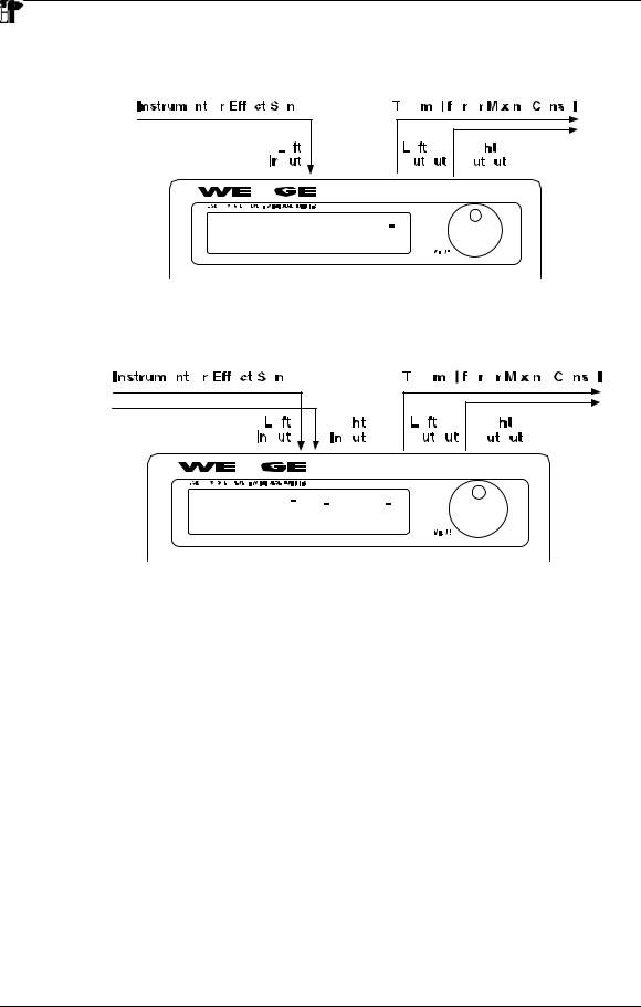
Interfacing Directly with Instruments
JWhen connecting audio cables and/or turning power on and off, make sure that all devices in your system are turned off and the volume controls are turned down.
The Wedge has two 1/4” balanced/unbalanced inputsand two 1/4” balanced/ unbalanced outputs. These provide three different audio hookup options:
•Mono: Connect an audio cable to the [LEFT] INPUT of the Wedge from a mono source, and another cable from the [LEFT] output of the Wedge to an amplification system or mixer input.
Wedge Reference Manual |
19 |
Chapter 2 – Connections
•Mono In, Stereo Out: While still using a mono input, you could connect two mono cords to the [LEFT] and [RIGHT] outputs of the Wedge to a stereo amplification system or two mixer inputs.
•Stereo: Connect two cables to the [LEFT] and [RIGHT] INPUTS of the Wedge from a stereo source , and two other mono cords from the [LEFT] and [RIGHT] OUTPUTS of the Wedge to a stereo amplification system or two mixer inputs.
Interfacing to a Mixing Console
The Wedge handles mono or stereo sends at all system levels. The input circuitry of the Wedge can easily handle professional +4 dBu levels (+20 dBu peaks), while having enough input and output gain to interface with the lower -10 dBV signal levels of home and project recording studios.
The Wedge may be connected to a mixing console in several different ways. It can be used to effect several instruments at once by using the auxiliary send and return controls of the mixer. Another method of interfacing is to connect the unit directly to the insert send and return patch points of the channel that is to be effected. Still another way of interfacing the Wedge to a mixer or recording console would be inline across the output of your mixing console. This last setup would be used only if you needed to affect the entire mix.
20 |
Wedge Reference Manual |

Connections – Chapter 2
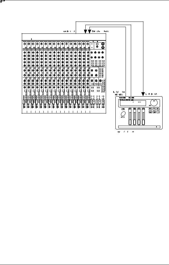
Using Aux Sends
Generally, mixing consoles provide two types of auxiliary sends: pre-fader sends for creating a cue (headphone) mix, and individual, post-fader effect sends. Typically, if a mixer has more than two sends per channel (4, 6 or 8, perhaps), the first two sends are reserved for the cue sends, while the remaining sends are used to feed effects, such as the Wedge. If you are using a mixer with more than two sends, connect the Wedge using post-fader sends.
Using a mixer’s aux sends poses a distinct advantage: each channel has its own level control feeding the aux output (and eventually the Wedge input). This allows you to make a mix of any channels you want to go to the effects by using the individual channels’ aux send levels on the mixer. Most consoles also have aux master controls, which set the overall level of each aux output. Coming back from the Wedge’s outputs into the mixer, you have two options:
•connecting to dedicated return inputs, or
•connecting to channel inputs.
The former is good if your mixer provides dedicated inputs (called returns) for effect devices like the Wedge. If your mixer does not have these, or you have already used them all, consider connecting the Wedge to channel inputs (if there are any remaining). This option also allows you to pan and EQ the effects, or to send them to the headphone or monitor mix.
No matter where you connect the output of the Wedge into the mixer, you are in control of the balance between the mixer’s channel inputs (the uneffected signal being routed to the aux sends and the Mix), and the effect returns coming from the Wedge. The effect returns generally should only contain effected signal, and not have any uneffected signal mixed with it (since these two signals are blended together at the mixer). Therefore, it may be necessary to modify the mix of each channel in the Program you are using so that only effected signal is present at the Wedge’s outputs. This can be done in two ways:
•Set each effect’s Mix parameters to 100% (wet signal only)
•Turn on the Dry Defeat function.
For more information about Dry Defeat, see Chapter 1.
Mono In - Stereo Out: If you only want to feed the Wedge a mono input, but wish to connect both of its outputs back to the mixer, you will need three 1/4" audio cables. Connect a balanced or unbalanced cable(s) from an aux send of the mixer to the [LEFT] input of the Wedge, and two other balanced or unbalanced cable(s) from the [LEFT] and [RIGHT] outputs of the Wedge to a stereo effect return or other mixer input.
For most of its programs, especially reverb programs, the Wedge synthesizes a stereo image from a single input, emulating the effect of a single source reflecting off the left and right sides of a room. This Mono In hookup allows you to get the benefit of these stereo effects, while using only one effect send. But other dual/parallel programs are best used with a stereo input, described below. Use this Mono In - Stereo Out hookup only if you don't
Wedge Reference Manual |
21 |
Chapter 2 – Connections
have enough Aux sends from your mixer to use the Stereo In hookup described below.
Stereo In - Stereo Out: This connection is similar to the one described above. However, by utilizing two sends from the mixer, we add one more cable from a different aux send to the [RIGHT] input of the Wedge and can now send a stereo
22 |
Wedge Reference Manual |

Connections – Chapter 2
signal to the Wedge’s inputs.
Certain Wedge programs allow you to use the left and right inputs separately, creating a separate effect for each input. The DELAY:DELAY, CHORUS:CHORUS, ROOM+HALL, ROOM+PLATE configurations are examples of this kind of multieffect that, essentially, allow you to use the Wedge as two independent mono or stereo effect units. For this reason, we recommend using the Stereo In - Stereo Out hookup whenever possible to get the most out of the Wedge.
Using Inserts
By using individual channel inserts, you can dedicate the Wedge to a specific channel (or pair of channels) on the mixer. The Insert connections on the back of the mixer provide a way of “inserting” external processing equipment into the signal path. The insert occurs after the input amplifier, and before the main fader; essentially it is the same as connecting the source (instrument or microphone) into the Wedge before the mixer’s channel input. However, some mixing console’s inserts come after the EQ section, and may therefore be different from the original signal. If nothing is connected to the channel’s Insert jack, the signal is not routed there.
Usually, insert connections require a special, stereo-splitting Y-cord to be connected (one stereo plug provides both send and return while two mono plugs connect separately to an input and output). Stereo Plugs are known as TRS connectors (tip- ring-sleeve). The tip of the stereo plug carries the send or output of the insert jack, while the ring brings back the return. The sleeve represents a common ground for both signals.
Mono: Connect a 1/4" TRS (tip-ring-sleeve) Y-cable to the Insert jack of a single channel on a mixing console. Connect the other end of the cable (which splits into two, 1/4" mono connectors) to the [LEFT] input and [LEFT] output, respectively. If
Wedge Reference Manual |
23 |
 Loading...