


 Loading...
3Com® Stackable Switch
Family
Advanced Configuration Guide
3Com Switch 5500
3Com Switch 5500G
3Com Switch 4500
3Com Switch 4200G
3Com Switch 4210
www.3Com.com
Part Number: 10016492 Rev. AB Published: February 2008
3Com Corporation
350 Campus Drive
Marlborough, MA
USA 01752-3064
Copyright © 2006-2008, 3Com Corporation. All rights reserved. No part of this documentation may be reproduced in any form or by any means or used to make any derivative work (such as translation, transformation, or adaptation) without written permission from 3Com Corporation.
3Com Corporation reserves the right to revise this documentation and to make changes in content from time to time without obligation on the part of 3Com Corporation to provide notification of such revision or change.
3Com Corporation provides this documentation without warranty, term, or condition of any kind, either implied or expressed, including, but not limited to, the implied warranties, terms or conditions of merchantability, satisfactory quality, and fitness for a particular purpose. 3Com may make improvements or changes in the product(s) and/or the program(s) described in this documentation at any time.
If there is any software on removable media described in this documentation, it is furnished under a license agreement included with the product as a separate document, in the hard copy documentation, or on the removable media in a directory file named LICENSE.TXT or !LICENSE.TXT. If you are unable to locate a copy, please contact 3Com and a copy will be provided to you.
UNITED STATES GOVERNMENT LEGEND
If you are a United States government agency, then this documentation and the software described herein are provided to you subject to the following:
All technical data and computer software are commercial in nature and developed solely at private expense. Software is delivered as “Commercial Computer Software” as defined in DFARS 252.227-7014 (June 1995) or as a “commercial item” as defined in FAR 2.101(a) and as such is provided with only such rights as are provided in 3Com’s standard commercial license for the Software. Technical data is provided with limited rights only as provided in DFAR 252.227-7015 (Nov 1995) or FAR 52.227-14 (June 1987), whichever is applicable. You agree not to remove or deface any portion of any legend provided on any licensed program or documentation contained in, or delivered to you in conjunction with, this User Guide.
Unless otherwise indicated, 3Com registered trademarks are registered in the United States and may or may not be registered in other countries.
3Com and the 3Com logo are registered trademarks of 3Com Corporation.
Cisco is a registered trademark of Cisco Systems, Inc.
Funk RADIUS is a registered trademark of Funk Software, Inc.
Aegis is a registered trademark of Aegis Group PLC.
Intel and Pentium are registered trademarks of Intel Corporation. Microsoft, MS-DOS, Windows, and Windows NT are registered trademarks of Microsoft Corporation. Novell and NetWare are registered trademarks of Novell, Inc. UNIX is a registered trademark in the United States and other countries, licensed exclusively through X/Open Company, Ltd.
IEEE and 802 are registered trademarks of the Institute of Electrical and Electronics Engineers, Inc.
All other company and product names may be trademarks of the respective companies with which they are associated.
ENVIRONMENTAL STATEMENT
It is the policy of 3Com Corporation to be environmentally-friendly in all operations. To uphold our policy, we are committed to:
Establishing environmental performance standards that comply with national legislation and regulations.
Conserving energy, materials and natural resources in all operations.
Reducing the waste generated by all operations. Ensuring that all waste conforms to recognized environmental standards. Maximizing the recyclable and reusable content of all products.
Ensuring that all products can be recycled, reused and disposed of safely.
Ensuring that all products are labelled according to recognized environmental standards.
Improving our environmental record on a continual basis.
End of Life Statement
3Com processes allow for the recovery, reclamation and safe disposal of all end-of-life electronic components.
Regulated Materials Statement
3Com products do not contain any hazardous or ozone-depleting material.
CONTENTS
ABOUT THIS GUIDE
Conventions 9
Related Documentation 9
Products Supported by this Document 10
1 LOGIN CONFIGURATION GUIDE
Logging In from the Console Port |
13 |
Logging In Through Telnet 15 |
|
Configuring Login Access Control |
18 |
2 VLAN CONFIGURATION GUIDE
Configuring Port-Based VLAN 21
Configuring Protocol-Based VLAN 23
3 IP ADDRESS CONFIGURATION GUIDE
IP Address Configuration Guide 27
4 VOICE VLAN CONFIGURATION GUIDE
Configuring Voice VLAN 29
Precautions 32
5 GVRP CONFIGURATION GUIDE
Configuring GVRP 33
6 PORT BASIC CONFIGURATION GUIDE
Configuring the Basic Functions of an Ethernet Port 39
7 LINK AGGREGATION CONFIGURATION GUIDE
Configuring Link Aggregation 41
8 PORT ISOLATION CONFIGURATION GUIDE
Configuring Port Isolation 45
4 3COM STACKABLE SWITCHES ADVANCED CONFIGURATION GUIDE
9 |
PORT SECURITY CONFIGURATION GUIDE |
|
|
Configuring Port Security autolearn Mode 47 |
|
|
Configuring Port Security mac-authentication Mode |
48 |
|
Configuring Port Security userlogin-withoui Mode |
51 |
|
Configuring Port Security mac-else-userlogin-secure-ext Mode 55 |
|
10 |
PORT BINDING CONFIGURATION GUIDE |
|
|
Configuring a Port Binding 59 |
|
11 MAC ADDRESS TABLE MANAGEMENT CONFIGURATION GUIDE
|
MAC Address Table Management |
61 |
|
|
||
12 DLDP CONFIGURATION GUIDE |
|
|
||||
|
Configuring DLDP |
63 |
|
|
|
|
13 AUTO DETECT CONFIGURATION GUIDE |
|
|||||
|
Auto Detect Implementation in Static Routing 67 |
|
||||
|
Auto Detect Implementation in VRRP |
69 |
|
|||
|
Auto Detect Implementation in VLAN Interface Backup 72 |
|||||
14 MSTP CONFIGURATION GUIDE |
|
|
||||
|
Configuring MSTP |
77 |
|
|
|
|
|
Configuring VLAN-VPN Tunneling |
80 |
|
|
||
|
Configuring RSTP |
83 |
|
|
|
|
|
Configuring Digest Snooping and Rapid Transition |
88 |
||||
15 |
ROUTING CONFIGURATION GUIDE |
|
||||
|
Configuring Static Routes 93 |
|
|
|
||
|
Configuring RIP |
95 |
|
|
|
|
|
Configuring OSPF |
98 |
|
|
|
|
|
Configuring OSPF DR Election |
102 |
|
|
||
|
Configuring a (Totally) Stub Area |
106 |
|
|
||
|
Configuring a (Totally) NSSA Area |
111 |
|
|||
|
Configuring OSPF Route Summarization |
117 |
|
|||
|
Configuring OSPF Virtual Link |
126 |
|
|
||
|
Configuring Routing Policies |
128 |
|
|
||
16 |
MULTICAST CONFIGURATION GUIDE |
|
||||
|
Configuring IGMP Snooping |
135 |
|
|
||
|
Configuring IGMP Snooping Only |
138 |
|
|||
|
Configuring Multicast VLAN |
142 |
|
|
||
|
Configuring PIM-SM plus IGMP plus IGMP Snooping |
146 |
||||
|
Configuring PIM-DM plus IGMP |
155 |
|
|
||
Contents 5
|
Configuring Anycast RP Application |
159 |
|
|
||||
17 |
802.1X CONFIGURATION GUIDE |
|
|
|
||||
|
Configuring 802.1x Access Control |
165 |
|
|
|
|||
18 |
AAA CONFIGURATION GUIDE |
|
|
|
|
|||
|
Configuring RADIUS Authentication for Telnet Users |
169 |
||||||
|
Configuring Dynamic VLAN Assignment with RADIUS Authentication 171 |
|||||||
|
Configuring Local Authentication for Telnet Users |
173 |
|
|||||
|
Configuring HWTACACS Authentication for Telnet Users |
174 |
||||||
|
Configuring EAD |
176 |
|
|
|
|
|
|
19 |
MAC AUTHENTICATION CONFIGURATION GUIDE |
|||||||
|
Configuring MAC Authentication |
179 |
|
|
|
|||
20 |
VRRP CONFIGURATION GUIDE |
|
|
|
||||
|
Single VRRP Group Configuration |
183 |
|
|
|
|||
|
Multiple VRRP Groups Configuration |
186 |
|
|
||||
|
VRRP Interface Tracking |
188 |
|
|
|
|
|
|
|
VRRP Port Tracking |
191 |
|
|
|
|
|
|
21 |
DHCP CONFIGURATION GUIDE |
|
|
|
||||
|
DHCP Server Global Address Pool Configuration Guide |
195 |
||||||
|
DHCP Server Interface Address Pool Configuration Guide |
198 |
||||||
|
DHCP Relay Agent Configuration Guide |
199 |
|
|
||||
|
DHCP Snooping Configuration Guide 201 |
|
|
|||||
|
DHCP Accounting Configuration Guide |
203 |
|
|
||||
|
DHCP Client Configuration Guide |
205 |
|
|
|
|||
22 |
ACL CONFIGURATION GUIDE |
|
|
|
|
|||
|
Configuring Basic ACLs |
207 |
|
|
|
|
|
|
|
Configuring Advanced ACLs |
208 |
|
|
|
|
||
|
Configuring Ethernet Frame Header ACLs |
209 |
|
|
||||
|
Configuring User-Defined ACLs |
211 |
|
|
|
|||
23 |
QOS/QOS PROFILE CONFIGURATION GUIDE |
|
||||||
|
Configuring Traffic Policing and LR |
215 |
|
|
|
|||
|
Configuring Priority Marking and Queue Scheduling |
217 |
||||||
|
Configuring Traffic Redirection and Traffic Accounting |
220 |
||||||
|
Configuring QoS Profile |
222 |
|
|
|
|
|
|
24 |
WEB CACHE REDIRECTION CONFIGURATION GUIDE |
|||||||
|
Configuring Web Cache Redirection |
225 |
|
|
||||
6 3COM STACKABLE SWITCHES ADVANCED CONFIGURATION GUIDE
25 |
MIRRORING CONFIGURATION GUIDE |
|
|
|||||
|
Local Port Mirroring Configuration |
229 |
|
|
||||
|
Remote Port Mirroring Configuration |
231 |
|
|
||||
|
Traffic Mirroring Configuration |
236 |
|
|
||||
26 |
XRN CONFIGURATION GUIDE |
|
|
|
||||
|
XRN Fabric Configuration |
239 |
|
|
|
|
||
27 |
CLUSTER CONFIGURATION GUIDE |
|
|
|||||
|
Cluster Configuration |
247 |
|
|
|
|
||
|
Network Management Interface Configuration 251 |
|
||||||
|
Cluster Configuration in Real Networking |
254 |
|
|||||
28 |
POE/POE PROFILE CONFIGURATION GUIDE |
|
||||||
|
PoE Configuration 259 |
|
|
|
|
|
||
|
PoE Profile Configuration |
261 |
|
|
|
|
||
29 |
UDP HELPER CONFIGURATION GUIDE |
|
||||||
|
UDP Helper Configuration Guide |
265 |
|
|
||||
30 |
SNMP-RMON CONFIGURATION GUIDE |
|
||||||
|
SNMP Configuration |
267 |
|
|
|
|
|
|
|
RMON Configuration |
269 |
|
|
|
|
||
31 |
NTP CONFIGURATION GUIDE |
|
|
|
||||
|
NTP Client/Server Mode Configuration 271 |
|
||||||
|
NTP Symmetric Peers Mode Configuration |
272 |
|
|||||
|
NTP Broadcast Mode Configuration |
273 |
|
|
||||
|
NTP Multicast Mode Configuration |
275 |
|
|
||||
|
NTP Client/Server Mode with Authentication Configuration 276 |
|
||||||
32 |
SSH CONFIGURATION GUIDE |
|
|
|
||||
|
Configuring the Switch to Act as the SSH Server and Use Password |
|
||||||
|
Authentication |
279 |
|
|
|
|
|
|
|
Configuring the Switch to Act as the SSH Server and Use RSA Authentication |
283 |
||||||
|
Configuring the Switch to Act as the SSH Client and Use Password |
|
||||||
|
Authentication |
290 |
|
|
|
|
|
|
|
Configuring the Switch to Act as the SSH Client and Use RSA Authentication |
292 |
||||||
|
Configuring the Switch to Act as the SSH Client and Not to Support First-Time |
|
||||||
|
Authentication |
295 |
|
|
|
|
|
|
|
Configuring SFTP |
300 |
|
|
|
|
|
|
33 |
FTP AND TFTP CONFIGURATION GUIDE |
|
||||||
|
Configuring a Switch as FTP Server |
305 |
|
|
||||
Contents |
7 |
|
Configuring a Switch as FTP Client |
307 |
|
|
|
|
|
Configuring a Switch as TFTP Client |
309 |
|
|
|
|
34 |
INFORMATION CENTER CONFIGURATION GUIDE |
|||||
|
Outputting Log Information to a Unix Log Host |
311 |
|
|
||
|
Outputting Log Information to a Linux Log Host |
313 |
|
|
||
|
Outputting Log and Trap Information to a Log Host Through the Same Channel 314 |
|||||
|
Outputting Log Information to the Console 317 |
|
|
|||
|
Displaying the Time Stamp with the UTC Time Zone |
318 |
||||
|
Use of the Facility Argument in Log Information Output |
319 |
||||
35 |
VLAN-VPN CONFIGURATION GUIDE |
|
|
|
||
|
Configuring VLAN-VPN 321 |
|
|
|
|
|
|
Configuring BPDU Tunnel |
324 |
|
|
|
|
36 |
REMOTE-PING CONFIGURATION GUIDE |
|
|
|
||
|
Remote-ping Configuration |
327 |
|
|
|
|
37 |
DNS CONFIGURATION GUIDE |
|
|
|
|
|
|
Static Domain Name Resolution Configuration Guide |
|
329 |
|||
|
Dynamic Domain Name Resolution Configuration Guide |
330 |
||||
38 |
ACCESS MANAGEMENT CONFIGURATION GUIDE |
|||||
|
Configuring Access Management |
333 |
|
|
|
|
|
Configuring Access Management with Port Isolation |
335 |
||||
8 3COM STACKABLE SWITCHES ADVANCED CONFIGURATION GUIDE

ABOUT THIS GUIDE
Provides advanced configuration examples for the 3Com stackable switches, which includes the following:
■3Com Switch 5500
■3Com Switch 5500G
■3Com Switch 4500
■3Com Switch 4200G
■3Com Switch 4210
|
This guide is intended for Qualified Service personnel who are responsible for |
||
|
configuring, using, and managing the switches. It assumes a working knowledge |
||
|
of local area network (LAN) operations and familiarity with communication |
||
|
protocols that are used to interconnect LANs. |
||
n |
Always download the Release Notes for your product from the 3Com World Wide |
||
|
Web site and check for the latest updates to software and product |
||
|
documentation: |
|
|
|
http://www.3com.com |
|
|
|
|
||
Conventions |
Table 1 lists icon conventions that are used throughout this guide. |
||
|
Table 1 |
Notice Icons |
|
|
|
|
|
|
Icon |
Notice Type |
Description |
n
c
Information note |
Information that describes important features or |
|
instructions. |
Caution |
Information that alerts you to potential loss of data |
|
or potential damage to an application, system, or |
|
device. |
|
w |
Warning |
Information that alerts you to potential personal |
|
|
injury. |
|
|
|
|
|
|
|
|
|
Related |
The following manuals offer additional information necessary for managing your |
Documentation |
Stackable Switch. Consult the documents that apply to the switch model that you |
|
are using. |
|
■ 3Com Switch Family Command Reference Guides — Provide detailed |
|
descriptions of command line interface (CLI) commands, that you require to |
|
manage your Stackable Switch. |

10 ABOUT THIS GUIDE
■3Com Switch Family Configuration Guides— Describe how to configure your Stackable Switch using the supported protocols and CLI commands.
■3Com Switch Family Quick Reference Guides — Provide a summary of command line interface (CLI) commands that are required for you to manage your Stackable Switch .
■3Com Stackable Switch Family Release Notes — Contain the latest information about your product. If information in this guide differs from information in the release notes, use the information in the Release Notes.
These documents are available in Adobe Acrobat Reader Portable Document
Format (PDF) on the 3Com World Wide Web site:
http://www.3com.com/
Products Supported by this Document
Table 2 Supported Products
Product |
Orderable |
Description |
|
SKU |
|
4210 |
3CR17331-91 |
Switch 4210 9-Port |
4210 |
3CR17332-91 |
Switch 4210 18-Port |
4210 |
3CR17333-91 |
Switch 4210 26-Port |
4210 |
3CR17334-91 |
Switch 4210 52-Port |
4210 |
3CR17341-91 Switch 4210 PWR 9-Port |
|
4210 |
3CR17342-91 Switch 4210 PWR 18-Port |
|
4210 |
3CR17343-91 Switch 4210 PWR 26-Port |
|
4500 |
3CR17561-91 |
Switch 4500 26-Port |
4500 |
3CR17562-91 |
Switch 4500 50-Port |
4500 |
3CR17571-91 Switch 4500 PWR 26-Port |
|
4500 |
3CR17572-91 Switch 4500 PWR 50-Port |
|
5500 |
3CR17161-91 |
Switch 5500-EI 28-Port |
5500 |
3CR17162-91 |
Switch 5500-EI 52-Port |
5500 |
3CR17171-91 Switch 5500-EI PWR 28-Port |
|
5500 |
3CR17172-91 Switch 5500-EI PWR 52-Port |
|
4200G |
3CR17660-91 |
Switch 4200G 12-Port |
4200G |
3CR17661-91 |
Switch 4200G 24-Port |
4200G |
3CR17662-91 |
Switch 4200G 48-Port |
4200G |
3CR17671-91 Switch 4200G PWR 24-Port |
|
5500G |
3CR17250-91 Switch 5500G-EI 24 Port |
|
5500G |
3CR17251-91 |
Switch 5500G-EI 48-Port |
5500G |
3CR17252-91 Switch 5500G-EI PWR 24-Port |
|
5500G |
3CR17253-91 Switch 5500G-EI PWR 48-Port |
|
Products Supported by this Document 11
12 ABOUT THIS GUIDE
LOGIN CONFIGURATION GUIDE
1
n |
Unless otherwise specified, all the switches used in the following configuration |
|
examples and configuration procedures are Switch 5500 (release V03.02.04). |
Logging In from the You can log in locally from the console port to configure and maintain your switch, Console Port including configuring other login modes. The default login mode on the Switch
5500 is local console login.
Network Diagram Figure 1 Logging in from the console port to configure Telnet login
|
RS-232 |
Console port |
|
|
|
Configuration cable |
|
PC |
|
Switch |
|
Networking and As shown in Figure 1, use a console cable to connect the serial port of your Configuration PC/terminal to the console port of the switch. Log into the switch from the AUX Requirements user interface on the console port to configure Telnet login. The current user level
is manage level (level 3).
Applicable Products
Product series |
Software version |
Hardware version |
|
|
|
Switch 5500 |
Release V03.02.04 |
All versions |
Switch 5500G |
Release V03.02.04 |
All versions |
Switch 4500 |
Release V03.03.00 |
All versions |
Switch 4210 |
Release V03.01.00 |
All versions |
|
|
|
Configuration Procedure ■ Configure common attributes for Telnet login
# Set the level of commands accessible to the VTY 0 user to 2.
[3Com] user-interface vty 0 [3Com-ui-vty0] user privilege level 2
# Enable the Telnet service on VTY 0.
[3Com-ui-vty0] protocol inbound telnet
# Set the number of lines that can be viewed on the screen of the VTY 0 user to 30.
[3Com-ui-vty0] screen-length 30
14CHAPTER 1: LOGIN CONFIGURATION GUIDE
#Set the history command buffer size to 20 for VTY 0.
[3Com-ui-vty0] history-command max-size 20
# Set the idle-timeout time of VTY 0 to 6 minutes.
[3Com-ui-vty0] idle-timeout 6
■ Configure an authentication mode for Telnet login
The following three authentication modes are available for Telnet login: none, password, and scheme.
The configuration procedures for the three authentication modes are described below:
1 Configure not to authenticate Telnet users on VTY 0.
[3Com] user-interface vty 0
[3Com-ui-vty0] authentication-mode none
2Configure password authentication for Telnet login on VTY 0, and set the password to 123456 in plain text.
[3Com] user-interface vty 0
[3Com-ui-vty0] authentication-mode password
[3Com-ui-vty0] set authentication password simple 123456
3 Configure local authentication in scheme mode for login users.
# Create a local user named guest and enter local user view.
[3Com] local-user guest
# Set the authentication password to 123456 in plain text.
[3Com-luser-guest] password simple 123456
# Set the service type to Telnet and the user level to 2 for the user guest.
[3Com-luser-guest] service-type telnet level 2
[3Com-luser-guest] quit
# Enter VTY 0 user interface view.
[3Com] user-interface vty 0
# Set the authentication mode to scheme for Telnet login on VTY 0.
[3Com-ui-vty0] authentication-mode scheme
[3Com-ui-vty0] quit
# Specify the domain system as the default domain, and configure the domain to adopt local authentication in scheme mode.
[3Com] domain default enable system
[3Com] domain system
[3Com-isp-system] scheme local

Logging In Through Telnet 15
Complete Configuration ■ Telnet login configuration with the authentication mode being none
user-interface vty 0 authentication-mode none user privilege level 2 history-command max-size 20 idle-timeout 6 0 screen-length 30
protocol inbound telnet
■ Telnet login configuration with the authentication mode being password
user-interface vty 0 user privilege level 2
set authentication password simple 123456 history-command max-size 20
idle-timeout 6 0 screen-length 30 protocol inbound telnet
■ Telnet login configuration with the authentication mode being scheme
#
domain system
#
local-user guest password simple 123456 level 3
#
user-interface vty 0 authentication-mode scheme user privilege level 2 history-command max-size 20 idle-timeout 6 0 screen-length 30
protocol inbound telnet
Precautions None
Logging In Through You can telnet to your switch to manage and maintain it remotely.
Telnet
16 CHAPTER 1: LOGIN CONFIGURATION GUIDE
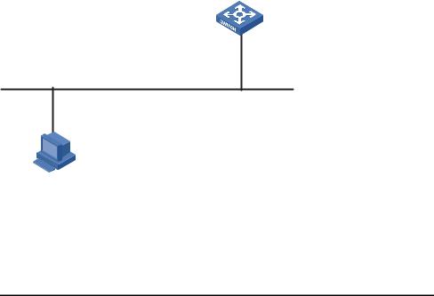
Network Diagram Figure 2 Telneting to the switch to configure console login
Ethernet1/0/1
Ethernet
User PC running Telnet
Networking and As shown in Figure 2, telnet to the switch to configure console login. The current Configuration user level is manage level (level 3).
Requirements
Applicable Products
Product series |
Software version |
Hardware version |
|
|
|
Switch 5500 |
Release V03.02.04 |
All versions |
Switch 5500G |
Release V03.02.04 |
All versions |
Switch 4500 |
Release V03.03.00 |
All versions |
Switch 4210 |
Release V03.01.00 |
All versions |
|
|
|
Configuration Procedure ■ Common configuration for console login
# Specify the level of commands accessible to the AUX 0 user interface to 2.
[3Com] user-interface aux 0
[3Com-ui-aux0] user privilege level 2
# Set the baud rate of the console port to 19200 bps.
[3Com-ui-aux0] speed 19200
# Set the number of lines that can be viewed on the screen of the AUX 0 user to 30.
[3Com-ui-aux0] screen-length 30
# Set the history command buffer size to 20 for AUX 0.
[3Com-ui-aux0] history-command max-size 20
# Set the idle-timeout time of AUX 0 to 6 minutes.
[3Com-ui-aux0] idle-timeout 6
■ Configure the authentication mode for console login
Logging In Through Telnet |
17 |
The following three authentication modes are available for console login: none, password, and scheme. The configuration procedures for the three authentication modes are described below:
1 Configure not to authenticate console login users.
[3Com] user-interface aux 0
[3Com-ui-aux0] authentication-mode none
2Configure password authentication for console login, and set the password to 123456 in plain text.
[3Com] user-interface aux 0
[3Com-ui-aux0] authentication-mode password
[3Com-ui-aux0] set authentication password simple 123456
3 Configure local authentication in scheme mode for console login.
# Create a local user named guest and enter local user view.
[3Com] local-user guest
# Set the authentication password to 123456 in plain text.
[3Com-luser-guest] password simple 123456
# Set the service type to Terminal and the user level to 2 for the user guest.
[3Com-luser-guest] service-type terminal level 2
[3Com-luser-guest] quit
# Enter AUX 0 user interface view.
[3Com] user-interface aux 0
# Set the authentication mode to scheme for console login.
[3Com-ui-aux0] authentication-mode scheme
Complete Configuration ■ Console login configuration with the authentication mode being none
#
user-interface aux 0 user privilege level 2
history-command max-size 20 idle-timeout 6 0
speed 19200 screen-length 30
■ Console login configuration with the authentication mode being password
#
user-interface aux 0 authentication-mode password user privilege level 2
set authentication password simple 123456 history-command max-size 20
idle-timeout 6 0 speed 19200 screen-length 30
18CHAPTER 1: LOGIN CONFIGURATION GUIDE
■Console login configuration with the authentication mode being scheme
#
local-user guest password simple 123456 service-type terminal level 2
#
user-interface aux 0 authentication-mode scheme user privilege level 2 history-command max-size 20 idle-timeout 6 0
speed 19200 screen-length 30
Precautions None
Configuring Login
Access Control
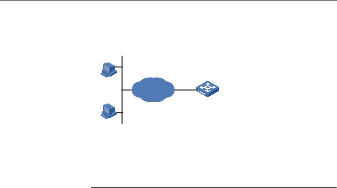
Network Diagram Figure 3 Network diagram for login access control
10.110.100.46 Host A
IP network
Switch
Host B 10.110.100.52
Networking and As shown in Figure 3, configure the switch to allow only Telnet/SNMP/WEB users Configuration at 10.110.100.52 and 10.110.100.46 to log in.
Requirements
Applicable Products
Product series |
Software version |
Hardware version |
|
|
|
Switch 5500 |
Release V03.02.04 |
All versions |
Switch 5500G |
Release V03.02.04 |
All versions |
Switch 4500 |
Release V03.03.00 |
All versions |
Switch 4210 |
Release V03.01.00 |
All versions |
|
|
|
Configuration Procedure # Create basic ACL 2000 and enter basic ACL view.
[3Com] acl number 2000 match-order config
[3Com-acl-basic-2000]
# Define ACL rules to allow only Telnet/SNMP/WEB users at 10.110.100.52 and 10.110.100.46 to log into the switch.
Configuring Login Access Control |
19 |
[3Com-acl-basic-2000] rule 1 permit source 10.110.100.52 0 [3Com-acl-basic-2000] rule 2 permit source 10.110.100.46 0 [3Com-acl-basic-2000] rule 3 deny source any [3Com-acl-basic-2000] quit
# Reference ACL 2000 to control Telnet login by source IP address.
[3Com] user-interface vty 0 4
[3Com-ui-vty0-4] acl 2000 inbound
# Reference ACL 2000 to control SNMP login by source IP address.
[3Com] snmp-agent community read aaa acl 2000 [3Com] snmp-agent group v2c groupa acl 2000
[3Com] snmp-agent usm-user v2c usera groupa acl 2000
# Reference ACL 2000 to control WEB login by source IP address.
[3Com] ip http acl 2000
Complete Configuration ■ Configuration for Telnet login control by source IP address
#
acl number 2000
rule 1 permit source 10.110.100.52 0 rule 2 permit source 10.110.100.46 0 rule 3 deny
#
user-interface vty 0 4 acl 2000 inbound
■ Configuration for SNMP login control by source IP address
#
acl number 2000
rule 1 permit source 10.110.100.52 0 rule 2 permit source 10.110.100.46 0 rule 3 deny
#
snmp-agent community read aaa acl 2000 snmp-agent group v2c groupa acl 2000 snmp-agent usm-user v2c usera groupa acl 2000
■ Configuration for WEB login control by source IP address
#
ip http acl 2000
#
acl number 2000
rule 1 permit source 10.110.100.52 0 rule 2 permit source 10.110.100.46 0 rule 3 deny
Precautions None
20 CHAPTER 1: LOGIN CONFIGURATION GUIDE
VLAN CONFIGURATION GUIDE
2
Configuring |
The VLAN technology allows you to divide a broadcast LAN into multiple distinct |
||||
Port-Based VLAN |
broadcast domains, each as a virtual workgroup. Port-based VLAN is the simplest |
||||
|
approach to VLAN implementation. The idea is to assign the ports on a switch to |
||||
|
different VLANs, confining the propagation of the packets received on a port |
||||
|
within the particular VLAN. Thus, separation of broadcast domains and division of |
||||
|
virtual groups are achieved. |
||||
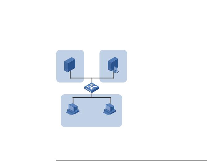
Network Diagram |
Figure 4 Network diagram for port-based VLAN configuration |
||||
|
|
Eth1/0/1 |
Eth1/0/2 |
|
|
|
|
|
Eth1/0/3 |
||
|
Server |
|
|
Host |
|
|
|
|
Eth1/0/10 |
||
|
|
|
|
|
|
|
|
|
|
|
|
|
|
Eth1/0/11 |
Eth1/0/12 |
||
|
Server |
|
|
Host |
|
Networking and Switch A and Switch B are connected each to a server and workstation. To Configuration guarantee data security for the servers, you need to isolate the servers from the Requirements workstations by creating VLANs. Allow the devices within a VLAN to communicate
with each other but not directly with the devices in another VLAN.
Applicable Products
Product series |
Software version |
Hardware version |
|
|
|
Switch 5500 |
Release V03.02.04 |
All versions |
Switch 5500G |
Release V03.02.04 |
All versions |
Switch 4500 |
Release V03.03.00 |
All versions |
Switch 4210 |
Release V03.01.00 |
All versions |
|
|
|
Configuration Procedure # Create VLAN 101 on Switch A and add Ethernet 1/0/1 to VLAN 101.
[SwitchA] vlan 101
[SwitchA-vlan101] port Ethernet 1/0/1
# Create VLAN 201 on Switch A and add Ethernet 1/0/2 to VLAN 201.
22 CHAPTER 2: VLAN CONFIGURATION GUIDE
[SwitchA-vlan101] quit
[SwitchA] vlan 201
[SwitchA-vlan201] port Ethernet 1/0/2
# Configure Ethernet 1/0/3 of Switch A to be a trunk port and to permit the packets carrying the tag of VLAN 101 or VLAN 201 to pass through.
[SwitchA-vlan201] quit
[SwitchA] interface Ethernet 1/0/3 [SwitchA-Ethernet1/0/3] port link-type trunk [SwitchA-Ethernet1/0/3] port trunk permit vlan 101 201
# Create VLAN 101 on Switch B, and add Ethernet 1/0/11 to VLAN 101.
[SwitchB] vlan 101
[SwitchB-vlan101] port Ethernet 1/0/11
# Create VLAN 201 on Switch B, and add Ethernet 1/0/12 to VLAN 201.
[SwitchB-vlan101] quit
[SwitchB] vlan 201
[SwitchB-vlan201] port Ethernet 1/0/12
# Configure Ethernet 1/0/10 of Switch B to be a trunk port and to permit the packets carrying the tag of VLAN 101 or VLAN 201 to pass through.
[SwitchB-vlan201] quit
[SwitchB] interface Ethernet 1/0/10 [SwitchB-Ethernet1/0/10] port link-type trunk [SwitchB-Ethernet1/0/10] port trunk permit vlan 101 201
Complete Configuration ■ Configuration on Switch A
#
vlan 101
#
vlan 201
#
interface Ethernet1/0/1 port access vlan 101
#
interface Ethernet1/0/2 port access vlan 201
#
interface Ethernet1/0/3 port link-type trunk
port trunk permit vlan 1 101 201
■ Configuration on Switch B
#
vlan 101
#
vlan 201
#
interface Ethernet1/0/10 port link-type trunk
port trunk permit vlan 1 101 201
|
|
Configuring Protocol-Based VLAN 23 |
|
# |
|
|
interface Ethernet1/0/11 |
|
|
port access vlan 101 |
|
|
# |
|
|
interface Ethernet1/0/12 |
|
|
port access vlan 201 |
|
Precautions |
■ After you assign the servers and the workstations to different VLANs, they |
|
|
cannot communicate with each other. For them to communicate, you need to |
|
|
configure a Layer 3 VLAN interface for each of them on the switches. |
|
|
■ After you telnet to an Ethernet port on a switch to make configuration, do not |
|
|
remove the port from its current VLAN. Otherwise, your Telnet connection will |
|
|
be disconnected. |
|
|
|
|
Configuring |
Protocol-based VLAN, or protocol VLAN, is another approach to VLAN |
|
Protocol-Based VLAN |
implementation other than port-based VLAN. With protocol VLAN, the switch |
|
|
compares each packet received without a VLAN tag against the protocol templates |
|
|
based on the encapsulation format and the specified field. If a match is found, the |
|
|
switch tags the packet with the corresponding VLAN ID. Thus, the switch can |
|
|
assign packets to a VLAN by protocol. |
|
Network Diagram |
Figure 5 Network diagram for protocol-based VLAN configuration |
|
|
IP Server |
AppleTalk Server |
Eth1/0/11 Eth1/0/12
Eth1/0/10
IP Host |
AppleTalk Host |
|
Workroom |
Networking and Configure the switch to automatically assign IP packets and Appletalk packets of Configuration the workroom to different VLANs, ensuring that the workstations can Requirements communicate with their respective servers properly.
Applicable Products
Product series |
Software version |
Hardware version |
|
|
|
Switch 5500 |
Release V03.02.04 |
All versions |
Switch 5500G |
Release V03.02.04 |
All versions |
Switch 4500 |
Release V03.03.00 |
All versions |
|
|
|
24 CHAPTER 2: VLAN CONFIGURATION GUIDE
Configuration Procedure # Create VLAN 100 and VLAN 200; add Ethernet 1/0/11 to VLAN 100 and Ethernet 1/0/12 to VLAN 200.
1 Create VLAN 100 and add Ethernet1/0/11 to VLAN 100.
[3Com] vlan 100
[3Com-vlan100] port Ethernet 1/0/11
2 Create VLAN 200 and add Ethernet 1/0/12 to VLAN 200.
[3Com-vlan100] quit
[3Com] vlan 200
[3Com-vlan200] port Ethernet 1/0/12
# Configure protocol templates and bind them to ports.
3Create a protocol template for VLAN 200 to carry Appletalk and a protocol template for VLAN 100 to carry IP.
[3Com-vlan200] protocol-vlan at
[3Com-vlan200] quit
[3Com] vlan 100
[3Com-vlan100] protocol-vlan ip
4Create a user-defined protocol template for VLAN 100 to carry ARP for IP communication, assuming that Ethernet_II encapsulation is used.
[3Com-vlan100] protocol-vlan mode ethernetii etype 0806
5Configure Ethernet 1/0/10 to be a hybrid port and to remove the outer VLAN tag when forwarding packets of VLAN 100 and VLAN 200.
[3Com-vlan100] quit
[3Com] interface Ethernet 1/0/10 [3Com-Ethernet1/0/10] port link-type hybrid
[3Com-Ethernet1/0/10] port hybrid vlan 100 200 untagged
6Bind Ethernet 1/0/10 to protocol template 0 and protocol template 1 of VLAN 100, and protocol template 0 of VLAN 200.
n |
When configuring a protocol template, you can assign a number to the template. |
|
If you fail to do that, the system automatically assigns the lowest available number |
|
to the template. Thus, in this configuration example, the two protocol templates |
|
for VLAN 100 are automatically numbered 0 and 1, and the protocol template for |
|
VLAN 200 is numbered 0. |
|
[3Com-Ethernet1/0/10] port hybrid protocol-vlan vlan 100 0 to 1 |
|
[3Com-Ethernet1/0/10] port hybrid protocol-vlan vlan 200 0 |
Complete Configuration |
# |
|
vlan 100 |
|
protocol-vlan 0 ip |
|
protocol-vlan 1 mode ethernetii etype 0806 |
|
# |
|
vlan 200 |
|
protocol-vlan 0 at |
|
# |
|
interface Ethernet1/0/10 |
|
port link-type hybrid |
|
port hybrid vlan 1 100 200 untagged |
|
port hybrid protocol-vlan vlan 100 0 |
|
port hybrid protocol-vlan vlan 100 1 |
Configuring Protocol-Based VLAN 25
port hybrid protocol-vlan vlan 200 0
#
interface Ethernet1/0/11 port access vlan 100
#
interface Ethernet1/0/12 port access vlan 200
Precautions Because IP depends on ARP for address resolution in Ethernet, you are recommended to configure the IP and ARP templates in the same VLAN and associate them with the same port to prevent communication failure.
Up to five protocol templates can be bound to a port.
26 CHAPTER 2: VLAN CONFIGURATION GUIDE

IP ADDRESS CONFIGURATION GUIDE
3
IP Address |
If you want to manage a remote Ethernet switch through network management |
||||||||
Configuration Guide |
or telnet, you need to configure an IP address for the remote switch and ensure |
||||||||
|
that the local device and the remote switch are reachable to each other. |
||||||||
|
A 32-bit IP address identifies a host on the Internet. Generally, a VLAN interface on |
||||||||
|
a switch is configured with one primary and four secondary IP addresses. |
||||||||
Network Diagram |
Figure 6 Network diagram for IP address configuration |
||||||||
|
172.16.1.0/24 |
|
|
Switch |
|||||
|
|
|
|
|
|
|
|||
|
|
|
|
|
Host B |
||||
|
|
|
|
|
|
|
|
-int1 |
|
|
|
|
|
|
|
|
|
||
|
|
|
|
172.16.1. |
|
|
|
172.16.1.1/24 |
|
|
|
|
|
|
|||||
|
|
|
|
|
|
172.16.2.1/24 sub |
|||
|
|
|
|
|
|
|
|
||
|
|
|
|
|
|
|
|
|
|
172.16.2.2/24
Host A
172.16.2.0/24
Networking and As shown in the above figure, the port in VLAN 1 on Switch is connected to a LAN Configuration in which hosts belong to two network segments: 172.16.1.0/24 and Requirements 172.16.2.0/24. It is required to enable the hosts in the LAN to communicate with
external networks through Switch, and to enable the hosts in the two network segments to communicate with each other.
Applicable Products
Product series |
Software version |
Hardware version |
|
|
|
Switch 5500 |
Release V03.02.04 |
All versions |
Switch 5500G |
Release V03.02.04 |
All versions |
Switch 4500 |
Release V03.03.00 |
All versions |
|
|
|
28 CHAPTER 3: IP ADDRESS CONFIGURATION GUIDE
Configuration Procedure |
Assign a primary and secondary IP addresses to VLAN-interface 1 of Switch to |
|
ensure that all the hosts on the LAN can access external networks through Switch. |
|
Set Switch as the gateway on all the hosts of the two network segments to ensure |
|
that they can communicate with each other. |
|
# Assign a primary IP address and a secondary IP address to VLAN-interface 1. |
|
<Switch> system-view |
|
[Switch] interface Vlan-interface 1 |
|
[Switch-Vlan-interface1] ip address 172.16.1.1 255.255.255.0 |
|
[Switch-Vlan-interface1] ip address 172.16.2.1 255.255.255.0 sub |
|
# Set the gateway address to 172.16.1.1 on the hosts in subnet 172.16.1.0/24, |
|
and to 172.16.2.1 on the hosts in subnet 172.16.2.0/24. |
|
# Ping Host B on Host A to verify the connectivity. |
Complete Configuration |
# |
|
interface Vlan-interface 1 |
|
ip address 172.16.1.1 255.255.255.0 |
|
ip address 172.16.2.1 255.255.255.0 sub |
|
# |
Precautions |
■ You can assign at most five IP addresses to an interface, among which one is |
|
the primary IP address and the others are secondary IP addresses. A newly |
|
specified primary IP address overwrites the previous one. |
|
■ The primary and secondary IP addresses of an interface cannot reside on the |
|
same network segment; an IP address of a VLAN interface must not be on the |
|
same network segment as that of a loopback interface on a device. |
|
■ A VLAN interface cannot be configured with a secondary IP address if the |
|
interface has obtained an IP address through BOOTP or DHCP. |
VOICE VLAN CONFIGURATION GUIDE
4
Configuring Voice |
In automatic mode, the switch configured with voice VLAN checks the source |
||
VLAN |
MAC address of each incoming packet against the voice device vendor OUI. If a |
||
|
match is found, the switch assigns the receiving port to the voice VLAN and tags |
||
|
the packet with the voice VLAN ID automatically. |
|
|
|
When the port joins the voice VLAN, a voice VLAN aging timer starts. If no voice |
||
|
packets have been received before the timer expires, the port leaves the voice |
||
|
VLAN. |
|
|
|
In manual mode, you need to manually assign a port to or remove the port from |
||
|
the voice VLAN. |
|
|
Network Diagram |
Figure 7 Network diagram for voice VLAN in automatic mode |
||
|
|
IP Phone1 |
|
|
|
(Tag) |
|
|
PC |
000f-e234-1234 |
VoIP Network |
|
|
Voice |
|
Gateway
Eth1/0/1
SwitchA 


 SwitchB
Eth1/0/2
Server
IP Phone2
(Untag)
Oui:000f-2200-0000
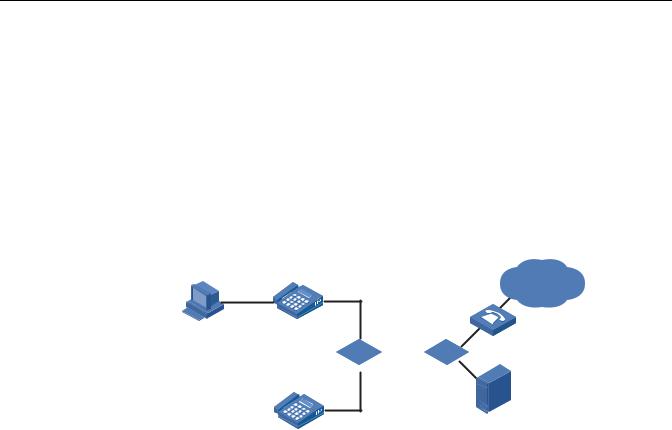
Networking and As shown in Figure 7, PC is connected to Ethernet 1/0/1 of Switch A through IP Configuration phone 1, and IP phone 2 is connected to Ethernet 1/0/2 of Switch A. IP phone 1 Requirements sends out voice traffic with the tag of the voice VLAN, while IP phone 2 sends out
voice traffic without any VLAN tag. Configure voice VLAN to satisfy the following requirements:
■VLAN 2 functions as the voice VLAN for transmitting voice traffic, and set the aging time of the voice VLAN to 100 minutes. VLAN 6 transmits user service data.
■Ethernet 1/0/1 and Ethernet 1/0/2 can recognize voice traffic automatically. Service data from PC and voice traffic are assigned to different VLANs and then transmitted to the server and the voice gateway respectively through Switch B.

30CHAPTER 4: VOICE VLAN CONFIGURATION GUIDE
■As the OUI address of IP phone 2 is not in the default voice device vendor OUI list of the switch, you need to add its OUI address 000f-2200-0000. In addition, configure its description as IP Phone2.
Applicable Products
Product series |
Software version |
Hardware version |
|
|
|
Switch 5500 |
Release V03.02.04 |
All versions |
Switch 5500G |
Release V03.02.04 |
All versions |
Switch 4500 |
Release V03.03.00 |
All versions |
|
|
|
Configuration Procedure # Create VLAN 2 and VLAN 6.
<SwitchA> system-view [SwitchA] vlan 2 [SwitchA-vlan2] quit [SwitchA] vlan 6 [SwitchA-vlan6] quit
# Set the aging time for the voice VLAN.
[SwitchA] voice vlan aging 100
# Add 000f-2200-0000 to the OUI address list and configure its description as IP Phone2.
[SwitchA] voice vlan mac-address 000f-2200-0000 mask ffff-ff00-0000
description IP Phone2
# Configure VLAN 2 as the voice VLAN.
[SwitchA] voice vlan 2 enable
# Set the voice VLAN operation mode on Ethernet 1/0/1 to automatic. This step is optional, because the default operation mode of the voice VLAN is automatic.
[SwitchA] interface Ethernet 1/0/1 [SwitchA-Ethernet1/0/1] voice vlan mode auto
# Configure Ethernet 1/0/1 as a trunk port.
[SwitchA-Ethernet1/0/1] port link-type trunk
# Set VLAN 6 as the default VLAN of Ethernet 1/0/1 and configure Ethernet 1/0/1 to permit the packets of VLAN 6 to pass through. (PC data will be transmitted in the VLAN.)
[SwitchA-Ethernet1/0/1] port trunk pvid vlan 6 [SwitchA-Ethernet1/0/1] port trunk permit vlan 6
# Enable voice VLAN on Ethernet 1/0/1.
[SwitchA-Ethernet1/0/1] voice vlan enable
n |
■ After the configuration above, PC data is automatically assigned to the default |
|
VLAN of Ethernet 1/0/1 (namely the service VLAN) for transmission. When IP |
Loading...