


 Loading...
Instruction |
Models UT550/UT520 |
Manual |
|
|
Digital Indicating Controllers |
User’s Manual for
Single-loop Control
IM 05D01C02-41E
IM 05D01C02-41E
1st Edition

Blank Page

<Toc> <Rev> |
i |
Introduction
Thank you for purchasing the UT550/UT520 digital indicating controller.
■ How to Use the Manuals
Purpose |
|
Manual Title |
Description |
|
|
|
|
|
|
Setup |
1. |
Installation |
Describes the tasks (installation, wiring, and others) required |
|
|
|
|
|
to make the controller ready for operations. |
|
|
|
|
|
Basic operation |
2. |
Initial Settings |
Describes examples of setting PV input types, control output |
|
|
|
|
|
types, and alarm types. Making settings described herein |
|
|
|
|
allows you to carry out basic control. |
Operating |
3. |
Operations |
Describes key operation sequences. For operation control |
|
procedures |
4.1 |
Troubleshooting |
through external contact inputs, See "1.5 Terminal Wiring |
|
and troubleshooting |
|
|
|
Diagrams" |
Brief operation |
5.1 |
Parameter Map |
Contains the parameter map used as a guideline for setting |
|
|
|
|
|
parameters. |
Function description |
5.2 |
Lists of |
Briefly describes the functions of parameters. In addition, |
|
and setpoint recording |
|
|
Parameters |
each parameter table has a User Setting column, where you |
|
|
|
|
can record your setpoints when setting them in the controller. |
|
|
|
|
|
■Regarding This User’s Manual
(1)This manual should be provided to the end user. Keep an extra copy or copies of the manual in a safe place.
(2)Read this manual carefully to gain a thorough understanding of how to operate this product before starting operation.
(3)This manual describes the functions of this product. Yokogawa M&C Corporation (hereinafter simply referred to as Yokogawa) does not guarantee the application of these functions for any particular purpose.
(4)Under absolutely no circumstances may the contents of this manual, in part or in whole, be transcribed or copied without permission.
(5)The contents of this manual are subject to change without prior notice.
(6)Every effort has been made to ensure that the details of this manual are accurate. However, should any errors be found or important information be omitted, please contact your nearest Yokogawa representative or our sales office.
Media No. IM 05D01C02-41E (CD) |
1st Edition : Mar. 2000 (YK) |
IM 05D01C02-41E 1st Edition: Mar. 31, 2000-00 |
All Rights Reserved Copyright © 2000, Yokogawa M&C Corporation |
|
|

<Toc> <Rev> |
ii |
■ Safety Precautions
The following symbol is indicated on the controller to ensure safe use.
This symbol on the controller indicates that the operator must refer to an explanation in the user’s manual in order to avoid the risk of injury or death of personnel or damage to the
 instrument. The manual describes how the operator should exercise special care to avoid CAUTION electric shock or other dangers that may result in injury or loss of life.
The following symbols are used in the hardcopy user’s manuals and in the user’s manual supplied on the CD-ROM.
 NOTE
NOTE
Indicates that operating the hardware or software in a particular manner may damage it or result in a system failure.
 IMPORTANT
Draws attention to information that is essential for understanding the operation and/or features of the controller.
■ Regarding Force Majeure
Yokogawa M&C Corporation assumes no liability for any loss or damage, direct or indirect, caused by the use of or unpredictable defects of the product.
IM 05D01C02-41E 1st Edition: Mar. 31, 2000-00

<Int> <Rev> |
Toc-1 |
Models UT550/UT520
Digital Indicating Controllers
User’s Manual for Single-loop Control
|
|
IM 05D01C02-41E 1st Edition |
|
CONTENTS |
|
||
1. |
Installation .............................................................................................. |
1-1 |
|
|
1.1 |
Model and Suffix Codes.................................................................................. |
1-1 |
|
1.2 |
How to Install................................................................................................... |
1-2 |
|
1.3 |
How to Connect Wires .................................................................................... |
1-5 |
|
1.4 |
Hardware Specifications ................................................................................ |
1-7 |
|
1.5 |
Terminal Wiring Diagrams ............................................................................ |
1-13 |
2. |
Initial Settings ........................................................................................ |
2-1 |
|
|
2.1 |
Names and Functions of Front Panel Parts ................................................... |
2-2 |
|
2.2 |
Setting PV Input Type (Setting First at Power-on) ......................................... |
2-3 |
|
2.3 |
Changing PV Input Type ................................................................................. |
2-7 |
|
2.4 |
Setting Control Output Type |
|
|
|
(except for a Position Proportional Controller) ............................................. |
2-9 |
|
2.5 |
Calibrating Valve Position |
|
|
|
(for a Position Proportional Controller Only) ............................................... |
2-11 |
|
2.6 |
Initializing Parameters .................................................................................. |
2-13 |
|
2.7 |
Changing Alarm Type ................................................................................... |
2-14 |
|
2.8 |
Description of Multiple Setpoints and PID................................................... |
2-17 |
3. |
Operations .............................................................................................. |
3-1 |
|
|
3.1 |
Monitoring-purpose Operating Displays |
|
|
|
Available during Operation ............................................................................ |
3-1 |
|
3.2 |
Setting Target Setpoint (SP) ........................................................................... |
3-3 |
|
3.3 |
Performing/Canceling Auto-tuning ................................................................ |
3-3 |
|
3.4 |
Setting PID Manually....................................................................................... |
3-5 |
|
3.5 |
Setting Alarm Setpoints .................................................................................. |
3-6 |
|
3.6 |
Selecting Target Setpoint Numbers (SPN) .................................................... |
3-7 |
|
3.7 |
Switching between Run and Stop .................................................................. |
3-8 |
|
3.8 |
Switching between AUTO and MAN ............................................................... |
3-8 |
|
3.9 |
Manipulating Control Output during Manual Operation ............................... |
3-9 |
|
3.10 |
Switching between Remote (REM) and Local (LCL) .................................... |
3-11 |
IM 05D01C02-41E 1st Edition: Mar. 31, 2000-00

<Int> <Rev> |
|
|
|
Toc-2 |
4. |
Troubleshooting and Maintenance ........................................................ |
4-1 |
||
|
4.1 |
Troubleshooting .............................................................................................. |
4-1 |
|
|
4.2 |
Maintenance .................................................................................................... |
4-6 |
|
|
|
4.2.1 |
Cleaning ........................................................................................... |
4-6 |
|
|
4.2.2 |
Replacing Brackets ........................................................................... |
4-6 |
|
|
4.2.3 |
Attaching Terminal Cover .................................................................. |
4-6 |
|
|
4.2.4 |
Replacing Parts with a Limited Service Life ....................................... |
4-8 |
|
|
4.2.5 |
Replacing Control Output Relays ...................................................... |
4-8 |
5. |
Parameters |
.............................................................................................. |
5-1 |
|
|
5.1 |
Parameter Map ................................................................................................ |
5-1 |
|
|
5.2 |
Lists .........................................................................................of Parameters |
5-6 |
|
6. |
Function Block ............................................Diagram and Descriptions |
6-1 |
||
IM 05D01C02-41E 1st Edition: Mar. 31, 2000-00

<Toc> |
< 1. Installation > |
1-1 |
1.Installation
This chapter describes installation, wiring, and other tasks required to make the controller ready for operation.
1.1Model and Suffix Codes
Before using the controller, check that the model and suffix codes match your order.
Model |
Suffix Code |
|
Description |
|
|
|
|
|
|
UT550 |
|
|
Digital indicating controller (provided with retransmission output and 15 VDC loop power supply as standard) |
|
|
|
|
|
|
|
-0 |
Standard type |
|
|
|
-1 |
Position proportional type |
|
|
Type |
-2 |
Heating/cooling type |
|
|
|
-3 |
Standard type (with 24 V DC loop power supply) |
||
|
-4 |
Position proportional type (with 24 V DC loop power supply) |
||
|
|
|
|
|
|
|
0 |
None |
|
|
|
1 |
With communication, remote input, 6 additional DIs and 4 additional DOs |
|
Optional functions |
|
2 |
With communication, remote input, and 1 additional DI |
|
|
|
3 |
With 5 additional DIs and 4 additional DOs |
|
|
|
4 |
With remote input and 1 additional DI |
|
|
|
|
|
|
|
|
|
||
Model |
Suffix Code |
|
Description |
|
|
|
|
|
|
UT520 |
|
|
Digital indicating controller (provided with retransmission output and 15 VDC loop power supply as standard) |
|
Type |
-0 |
Standard type |
|
|
|
|
|
|
|
|
|
0 |
None |
|
Optional functions |
|
7 |
Communication, remote input, and 2 additional DIs |
|
|
|
8 |
Remote input and 2 additional DIs |
|
|
|
|
|
|
Check that the following items are provided: |
|
|
• Digital indicating controller (of ordered model): ........................................... |
1 |
|
• |
Brackets (mounting hardware): .................................................................. |
1 pair |
• |
Unit label: ................................................................................................... |
1 |
• User’s Manuals for Single-loop Control: ..................................................... |
5 (A2 size) |
|
• User’s Manual (Reference) (CD-ROM Version): ......................................... |
1 |
|
■Correspondence between the Model and Suffix Codes, and the Contact Input/Output Terminals Provided
Check the model ordered and the presence/absence of contact inputs and outputs in the following table.
indicate that the contacts are available.
Model and Suffix |
|
|
Contact input terminals |
|
|
|
|
Contact output terminals |
|
|
||||||||
Codes |
|
DI1 |
DI2 |
DI3 |
DI4 |
DI5 |
DI6 |
DI7 |
DI8 |
DO1 |
DO2 |
|
DO3 |
DO4 |
DO5 |
|
DO6 |
DO7 |
|
|
|
|
|
|
|
|
|
|
|
|
|
|
|
|
|
|
|
UT550- |
0 |
|
|
|
|
|
|
|
|
|
|
|
|
|
|
|
|
|
|
|
|
|
|
|
|
|
|
|
|
|
|
|
|
|
|
|
|
UT550- |
1 |
|
|
|
|
|
|
|
|
|
|
|
|
|
|
|
|
|
|
|
|
|
|
|
|
|
|
|
|
|
|
|
|
|
|
|
|
UT550- |
2 |
|
|
|
|
|
|
|
|
|
|
|
|
|
|
|
|
|
|
|
|
|
|
|
|
|
|
|
|
|
|
|
|
|
|
|
|
UT550- |
3 |
|
|
|
|
|
|
|
|
|
|
|
|
|
|
|
|
|
|
|
|
|
|
|
|
|
|
|
|
|
|
|
|
|
|
|
|
UT550- |
4 |
|
|
|
|
|
|
|
|
|
|
|
|
|
|
|
|
|
|
|
|
|
|
|
|
|
|
|
|
|
|
|
|
|
|
|
|
Note: For details on the functions of contact inputs/outputs, see “1.5 Terminal Wiring Diagrams” .
IM 05D01C02-41E 1st Edition: Mar. 31, 2000-00
<Toc> |
|
|
|
|
|
|
|
|
< 1. Installation > |
1-2 |
||||||||
|
|
|
|
|
|
|
|
|
|
|
indicate that the contacts are available. |
|||||||
|
|
|
|
|
|
|
|
|
|
|
|
|
|
|
|
|
|
|
|
Model and Suffix |
|
|
Contact input terminals |
|
|
|
|
|
Contact output terminals |
|
|||||||
|
Codes |
DI1 |
DI2 |
DI3 |
DI4 |
DI5 |
DI6 |
DI7 |
DI8 |
DO1 |
|
DO2 |
|
DO3 |
DO4 |
DO5 |
DO6 |
DO7 |
|
|
|
|
|
|
|
|
|
|
|
|
|
|
|
|
|
|
|
|
UT520-00 |
|
|
|
|
|
|
|
|
|
|
|
|
|
|
|
|
|
|
|
|
|
|
|
|
|
|
|
|
|
|
|
|
|
|
|
|
|
UT520-07 |
|
|
|
|
|
|
|
|
|
|
|
|
|
|
|
|
|
|
|
|
|
|
|
|
|
|
|
|
|
|
|
|
|
|
|
|
|
UT520-08 |
|
|
|
|
|
|
|
|
|
|
|
|
|
|
|
|
|
|
|
|
|
|
|
|
|
|
|
|
|
|
|
|
|
|
|
|
Note: For details on the functions of contact inputs/outputs, see “1.5 Terminal Wiring Diagrams” .
1.2How to Install
 NOTE
NOTE
To install the controller, select a location where: |
|
|
|
|
|
|
|
|
|
|
|
|
|
|
|
(1) |
no one may accidentally touch the terminals, |
|
|
|
|
|
|
|
|
|
|
|
|
|
|
(2) |
mechanical vibrations are minimal, |
|
|
|
|
|
|
|
|
|
|
|
|
|
|
|
|
|
|
150mm |
|
|
|
|
|
|
|
|
|||
(3) |
corrosive gas is minimal, |
|
|
|
|
|
|
|
|
|
|
|
|
|
|
|
|
|
|
|
|
|
|
|
|
|
|
|
|
||
(4) |
temperature can be maintained at about 23°C |
|
|
|
|
|
|
|
|
|
|
|
|
|
|
|
|
|
|
|
|
|
|
|
|
|
|
|
|
||
|
150mm |
|
|
|
|
|
|
|
150mm |
|
|||||
|
|
|
|
|
|
|
|
|
|
|
|||||
|
and the fluctuation is minimal, |
|
|
|
|
|
|
|
|
|
|
|
|
|
|
|
|
|
|
|
|
|
|
150mm |
|||||||
(5) |
no direct radiant heat is present, |
|
|
|
|
|
|
|
|
|
|
|
|
|
|
|
|
|
|
|
|
|
|
|
|
|
|
|
|
||
(6)no magnetic disturbances are caused,
(7)no wind blows against the terminal board (reference junction compensation element),
(8)no water is splashed,
(9)no flammable materials are around,
Never place the controller directly on flammable items or equipment.
If the controller has to be installed close to flammable items or equipment, be sure to provide shielding panels all around the controller, at least 150mm away from every side; the panels should be made of either 1.43mm-thick metal-plated steel plates or 1.6mm-thick uncoated steel plates.
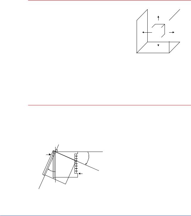
● Installation Position
Install the controller at an angle within 30° from horizontal with the front panel facing upward. Do not install it facing downward. The position of right and left sides should be horizontal.
Front panel
of controller Must not exceed 30
30 |
Rear of |
|
controller |
||
|
IM 05D01C02-41E 1st Edition: Mar. 31, 2000-00
<Toc> |
< 1. Installation > |
1-3 |
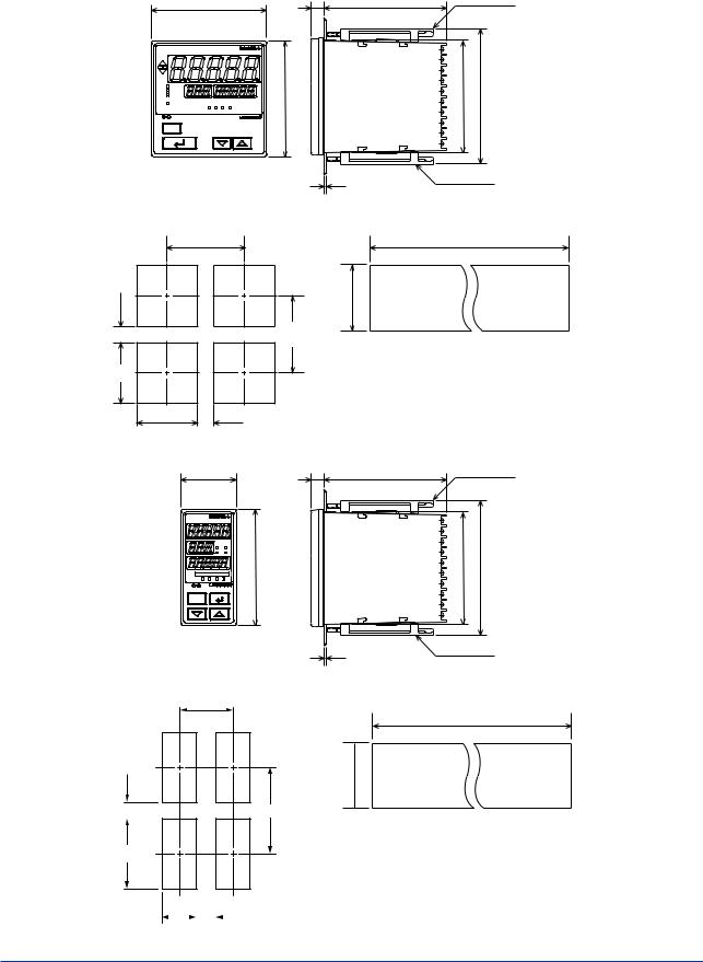
■ External Dimensions and Panel Cutout Dimensions
UT550
96
P V
CAS
REM
MAN
LP2 |
|
|
|
|
AL1 |
2 |
3 |
4 |
Unit: mm
11 |
100 |
Large bracket |
96 |
91.8 |
112 |
A / M
SET/ENT
|
Small bracket |
|
1 to 10 mm (Panel thickness) |
General installation |
Side-by-side close installation |
117 min. |
[(N-1) 96+92]+00.8 |
+0.8 92 0
(53) |
145 min. |
|
92+00.8
92+00.8 (25)
“N” stands for the number of controllers to be installed.
However, the measured value applies if N 5.
UT520 |
Unit: mm |
48 |
11 |
100 |
Small bracket |
PV
LP2 CAS
REM MAN
96
AL1 2 3 4
SET/ENT
A / M
General installation
70 min.
(53) |
145 min. |
|
|
|
|
92 + 00.8
91.8 |
112 |
Small bracket
1 to 10 mm (Panel thickness)
Side-by-side close installation
[(N-1) 48+45]+00.6
+0.8 92 0
“N” stands for the number of controllers to be installed.
However, the measured value applies if N 5.
45 + 00.6 |
|
(25) |
|||
|
|
|
|
|
|
IM 05D01C02-41E 1st Edition: Mar. 31, 2000-00
<Toc> |
< 1. Installation > |
1-4 |
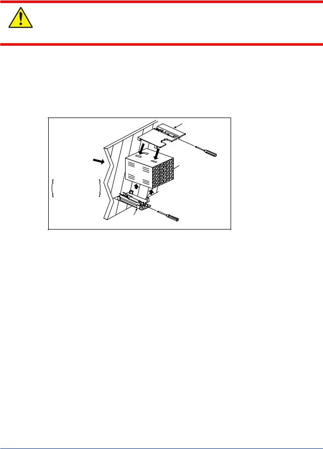
■ How to Install
Turn off the power to the controller before installing it on the panel because there is a possibility of electric shock.
CAUTION
After opening the mounting hole on the panel, follow the procedures below to install the controller:
1.Insert the controller into the opening from the front of the panel so that the terminal board on the rear is at the far side.
2.Set the brackets in place on the top and bottom of the controller as shown in the figure below, then tighten the screws of the brackets. Take care not to overtighten them.
Direction to insert the controller
Insert the controller into the opening at the front of the panel.
Large bracket
Panel |
(top mounting hardware) |
Terminal board
Insert a screwdriver into the brackets to tighten the screws.
Small bracket
(bottom mounting hardware)
IM 05D01C02-41E 1st Edition: Mar. 31, 2000-00
<Toc> |
< 1. Installation > |
1-5 |
1.3How to Connect Wires
1)Before carrying out wiring, turn off the power to the controller and check that the cables to be connected are not alive with a tester or the like because there is a possibility of
electric shock.
CAUTION 2) Wiring must be carried out by personnel who have basic electrical knowledge and practical experience.
 NOTE
NOTE
1)Provide power from a single-phase instrument power supply. If there is a lot of noise in the power line, insert an insulating transformer into the primary side of the line and use a line filter (recommended part: ZAC2205-00U from TDK) on the secondary side.
As a countermeasures against noise, do not place the primary and secondary power cables close to each other.
2)For thermocouple input, use shielded compensating lead wires for wiring. For RTD input, use shielded wires that have low conductor resistance and cause no significant differences in resistance between the three wires.
The cables to be used for wiring, terminal specifications, and recommended parts are as shown below.
3)Control output relays may be replaced. However, because they have a life of 100,000 times that of the resistance load, use auxiliary relays to turn on/off a load.
4)The use of inductance (L) loads such as auxiliary relays, motors and solenoid valves causes malfunction or relay failure; always insert a CR filter for use with alternating current or a diode for use with direct current, as a spark-removal surge suppression circuit, into the line in parallel with the load.
■ For DC Relay Wiring |
■ For AC Relay Wiring |
UT550/UT520 |
External DC power supply |
|||
|
|
|
|
|
O.C Relay |
|
|||
|
|
|
|
|
|
|
R |
|
|
|
Diode |
|
UT’s contact |
|
(Mount it directly |
|
Relay |
to the relay coil |
||
|
|||
(Use one with a relay coil rating |
terminal (socket).) |
||
less than the UT’s contact rating.) |
|
||
UT550/UT520  External AC power supply
|
|
R |
UT’s contact |
Relay |
CR filter |
|
||
(Use one with a relay coil |
(Mount it directly |
|
rating less than the UT’s |
to the relay coil |
|
|
contact rating.) |
terminal (socket).) |
IM 05D01C02-41E 1st Edition: Mar. 31, 2000-00
<Toc> |
< 1. Installation > |
1-6 |
|||||||||
● Cable Specifications and Recommended Cables |
|
|
|
|
|||||||
|
|
|
|
|
|
|
|
|
|
|
|
|
Purpose |
Name and Manufacturer |
|
|
|
|
|||||
|
|
|
|
|
|
|
|
|
|
|
|
|
Power supply, grounding, relay contact outputs |
600 V PVC insulated wires, JIS C 3307, 0.9 to 2.0 mm2 |
|
|
|
|
|||||
|
Thermocouple |
Shielded compensating lead wires, JIS C 1610, |
|
X- |
|
- |
|
- |
|
|
|
|
|
|
|
|
|
|
|||||
|
|
(See Yokogawa Electric’s GS 6B1U1-E.) |
|
|
|
|
|||||
|
|
|
|
|
|
|
|
|
|
|
|
|
RTD |
Shielded wires (three conductors), UL2482 (Hitachi Cable) |
|
|
|
|
|||||
|
|
|
|
|
|
|
|
|
|
|
|
|
Other signals |
Shielded wires |
|
|
|
|
|||||
|
|
|
|
|
|
|
|
|
|
|
|
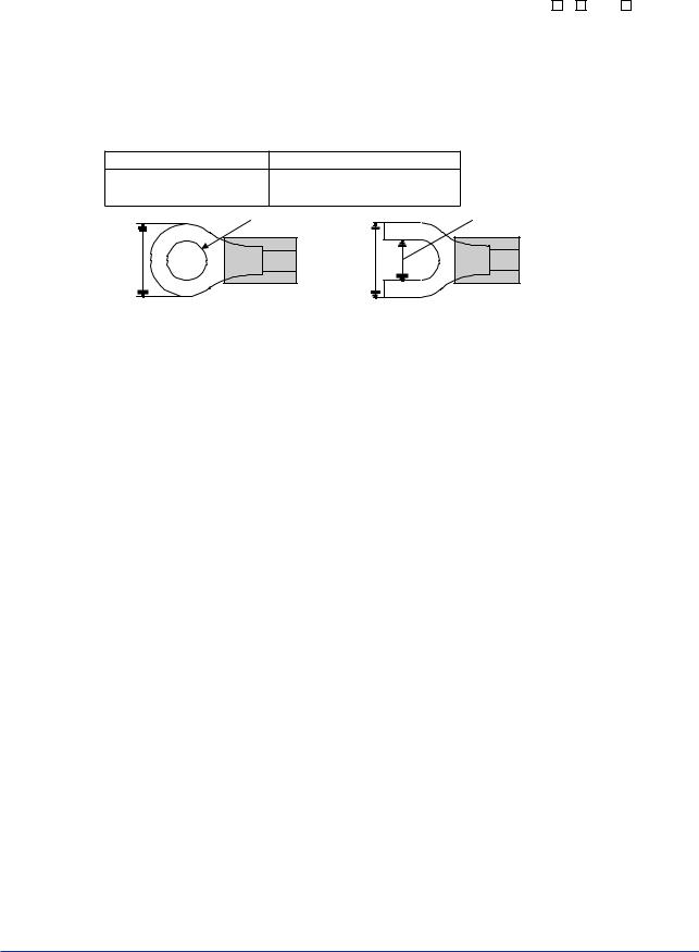
● Recommended Terminal Lugs
Applicable wire size
0.3 to 1.65 mm2
7 m m o r l e s s
Tightening torque |
|
|
0.8 N·m or less |
|
|
3 . 7 m m |
|
3 . 7 m m |
|
l e s s |
|
or |
o r |
|
m m |
|
|
|
|
|
|
7 |
|
● Terminal Covers
Target Model |
Part Number |
Sales Unit |
|
|
|
For UT550 |
T9115YD |
1 |
|
|
|
For UT520 |
T9115YE |
1 |
|
|
|
IM 05D01C02-41E 1st Edition: Mar. 31, 2000-00

<Toc> |
< 1. Installation > |
1-7 |
1.4Hardware Specifications
PV Input Signals
•Number of inputs: 1 (terminals 11 -12 -13 )
•Input type: Universal input system. The input type can be selected with the software.
•Sampling period: Can be selected from 50, 100, 200 and 500 ms. Initial value: 200 ms
•Burnout detection: Functions at TC, RTD, standard signal (0.4 to 2 V or 1 to 5 V) Upscale, downscale, and off can be specified.
For standard signal, burnout is determined to have occurred if it is 0.1 V or less.
•Input bias current: 0.05 A (for TC or RTD b-terminal)
•Measurement current (RTD): About 0.13 mA
•Input resistance: 1 M or more for thermocouple or mV input About 1 M for DC voltage input
•Allowable signal source resistance: 250 or less for thermocouple or mV input Effects of signal source resistance: 0.1 V/ or less
2 k or less for DC voltage input
Effects of signal source resistance: About 0.01%/100
•Allowable wiring resistance: for RTD input
Maximum 150 /wire: Conductor resistance between three wires should be equal However, 10 /wire for a maximum range of -150.0 to 150.0 C.
Wire resistance effect: 0.1 C /10
•Allowable input voltage: 10 V DC for thermocouple, mV, or RTD input20 V DC for DC voltage input
•Noise rejection ratio: 40 dB (50/60 Hz) or more in normal mode 120 dB (50/60 Hz) or more in common mode
•Reference junction compensation error: 1.0 C (15 to 35 C)1.5 C (0 to 15 C, 35 to 50 C)
•Applicable standards: JIS, IEC, DIN (ITS-90) for thermocouples and RTD
Remote Input Signals
Available only for controllers with remote input terminals.
•Number of inputs: 1 (terminals 21 - 22 )
•Input type: Settable in a range of 0-2, 0-10, 0.4-2.0, or 1-5 V DC
•Sampling period: 100, 200 and 500 ms
The sampling period of a remote input signal is associated with the PV input’s sampling period. If the PV input’s sampling period is 50 ms, however, the sampling period of a remote input signal lengthens to 100 ms.
•Input resistance: About 1 M
•Input accuracy: 0.3% 1 digit of input span for 0 to 2 V DC0.2% 1 digit of input span for 0 to 10 V DC
0.375% 1 digit of input span for 0.4 to 2.0 V DC0.3% 1 digit of input span for 1 to 5 V DC
Under standard operating conditions (23 2 C, 55 10% RH, power frequency of 50/ 60 Hz)
IM 05D01C02-41E 1st Edition: Mar. 31, 2000-00

<Toc> |
< 1. Installation > |
1-8 |
Feedback Resistance Input
Provided for position proportional type only (terminals 45 -46 -47 )
•Slide resistance value: 100 to 2.5 k of overall resistance (burnout detection for sliding wire provided)
•Measuring resolution: 0.1% of overall resistance
Loop Power Supply
Power is supplied to a two-wire transmitter.
(15 V DC: terminals 14 -15 ; 24 V DC: terminals 43 -44 )
A resistor (10 to 250 ) connected between the controller and transmitter converts a current signal into a voltage signal, which is then read via the PV input terminal. Supply voltage: 14.5 to 18.0 V DC, max. 21 mA (provided with a protection circuit against a field short-circuit); 21.6 to 28.0 V DC, max. 30 mA (only for models with 24 V DC loop power supply)
Retransmission Output
Either PV, target setpoint, or control output is output.
Either the retransmission output or the loop power supply can be used with terminals
14 -15 .
•Number of outputs: 1 or 2 (terminals 14 -15 , terminals 16 -17 )
•Output signal: 4-20, 0-20, 20-4, or 20-0 mA DC (where, outputting signal levels of less than 0 mA is not feasible)
•Load resistance: 600 or less
•Output accuracy: 0.1% of span ( 5% of span for 1 mA or less.)
Under standard operating conditions (23 2 C, 55 10% RH, power frequency of 50/ 60 Hz)
Control Output
Universal output system, The output type can be selected with the software.
Relay contact output(s) for the position proportional type
•Current output
(Standard type: terminals 16 -17 ; heating-side output: terminals 16 -17 , cooling-side output: terminals 46 -47 )
Number of outputs |
1 or 2 (two for heating/cooling type), |
|
switched between a voltage pulse output |
|
and current output. |
|
|
Output signal |
4-20, 0-20, 20-4, or 20-0 mA DC |
|
|
Load resistance |
600 or less |
|
|
Output accuracy |
0.1% of span |
|
( 5% of span for 1 mA or less) |
|
Under standard operating conditions (23 2 C, |
|
55 10% RH, power frequency of 50/60 Hz) |
|
|
IM 05D01C02-41E 1st Edition: Mar. 31, 2000-00

<Toc> |
< 1. Installation > |
1-9 |
•Voltage pulse output
(Standard type: terminals 16 -17 ; heating-side output: terminals 16 -17 , cooling-side output: terminals 46 -47 )
Number of |
1 or 2 (two for heating/cooling type), |
|
outputs |
switched between a voltage pulse output and current output. |
|
|
|
|
Output signal |
On-voltage = 12 |
V or more (load resistance: 600 Ω or more) |
|
Off-voltage = 0.1 V DC or less |
|
|
|
|
Resolution |
10 ms or |
0.1% of output, whichever is larger |
|
|
|
•Relay contact output
(Standard type: terminals 1 - 2 - 3 , heating-side output: terminals 1 - 2 - 3 , cooling-side output: terminals 48 - 49 - 50 , position proportional type: terminals 48 - 49 - 50 )
Number of outputs |
1 or 2(two for heating/cooling type) |
|
|
Output signal |
Three terminals (NC, NO, and common) |
|
|
Contact rating |
250 V AC or 30 V DC, 3 A (resistance load) |
|
|
Resolution |
10 ms or 0.1% of output, whichever is larger |
|
|
Contact Inputs
•Purpose: Target setpoint selection, remote/local mode switching, and run/stop switching
•Number of inputs: Differs with model and suffix codes as shown in the table below.
Model and Suffix Codes |
Number of Inputs |
|
|
|
|
UT550- |
0 |
2 |
|
|
|
UT550- |
1 |
8 |
|
|
|
UT550- |
2 |
3 |
|
|
|
UT550- |
3 |
7 |
|
|
|
UT550- |
4 |
3 |
|
|
|
UT520-00 |
|
2 |
|
|
|
UT520-07 |
|
4 |
|
|
|
UT520-08 |
|
4 |
|
|
|
•Input type: Non-voltage contact or transistor open collector input
•Input contact rating: 12 V DC, 10 mA or more
•On/off determination: For non-voltage contact input, contact resistance of 1 k or less is determined as “on” and contact resistance of 20 k or more as “off.”
For transistor open collector input, input voltage of 2 V or less is determined as “on” and leakage current must not exceed 100 A when “off.”
•Minimum status detection hold time: PV input’s sampling period 3
IM 05D01C02-41E 1st Edition: Mar. 31, 2000-00

<Toc> |
< 1. Installation > |
1-10 |
Contact Outputs
•Purpose: Alarm output, FAIL output, and others
•Number of outputs: Differs with the model and suffix code as shown in the table below.
Model and Suffix Codes |
Number of Outputs |
|
|
|
|
UT550- |
0 |
3 |
|
|
|
UT550- |
1 |
7 |
|
|
|
UT550- |
2 |
3 |
|
|
|
UT550- |
3 |
7 |
|
|
|
UT550- |
4 |
3 |
|
|
|
UT520-00 |
|
3 |
|
|
|
UT520-07 |
|
3 |
|
|
|
UT520-08 |
|
3 |
|
|
|
•Relay contact rating: 240 V AC, 1 A, or 30 V DC, 1 A
•Transistor contact rating: 24 V DC, 50 mA
Display Specifications
•PV display:
5-digit, 7-segment, red LEDs, character height of 20 mm for UT550 and 12 mm for UT520
•Setpoint display: 3-digit and 5-digit, 7-segment, red LEDs, character height of 9.3 mm (for both UT520 and UT550)
•Status indicating lamps: LEDs
Safety and EMC Standards
•Safety: Compliant with IEC1010-1: 1990 and EN61010-1: 1992 Approved by CSA1010
CSA1010 installation category (overvoltage category): CATII (IEC1010-1) Approved by UL508
•EMC standards: This instrument complies with the following EMC standards (the instrument continues to operate at a measuring accuracy of within 20% of the range during tests):
-EMI (emission), EN55011: Class A Group 1
-EMS (immunity), EN50082-2: 1995
Construction, Installation, and Wiring
• Construction: Only the front panel is dust-proof and drip-proof (protection class IP55)
For side-by-side close installation the controller loses its dust-proof and drip-proof protection.
•Material: ABS resin and polycarbonate
•Case color: Black
•Weight: About 1 kg or less
•Dimensions:
UT550 96 (W) 96 (H) 100 (depth from panel face) mm UT520 48 (W) 96 (H) 100 (depth from panel face) mm
IM 05D01C02-41E 1st Edition: Mar. 31, 2000-00

<Toc> |
< 1. Installation > |
1-11 |
•Installation: Panel-mounting type. With top and bottom mounting hardware (1 each)
•Panel cutout dimensions:
UT550 92+0.80 (W) 92+0.80 (H) mm
UT520 45+0.60 (W) 92+0.80 (H) mm
•Installation position: Up to 30° upward facing (not designed for facing downward)
•Wiring: M3.5 screw terminals (for signal wiring and power/ground wiring as well)
Power Supply Specifications
•Power supply: Rated voltage of 100 to 240 V AC ( 10%), 50/60 Hz
•Power consumption: Max. 20 VA (8.0 W max.)
•Data backup: Non-volatile memory (can be written to up to 100,000 times)
•Withstanding voltage
-Between primary terminals* and secondary terminals**: At least 1500 V AC for 1 minute (Note)
-Between primary terminals* and grounding terminal: At least 1500 V AC for 1 minute (Note)
-Between grounding terminal and secondary terminals**: At least 1500 V AC for 1 minute
-Between secondary terminals**: At least 500 V AC for 1 minute
*Primary terminals indicate power terminals and relay output terminals **Secondary terminals indicate analog I/O signal, voltage pulse output, and contact
input terminals
Note : The withstanding voltage is specified as 2300 VAC per minute to provide a margin of safety.
•Insulation resistance: 20 M or more at 500 V DC between power terminals and grounding terminal
•Grounding: Class 3 grounding (grounding resistance of 100 or less)
Signal Isolations
•PV input terminals: Isolated from other input/output terminals. Not isolated from the internal circuit.
•Remote input terminals: Isolated from other input/output terminals and the internal circuit.
•15 V DC loop power supply terminals: Not isolated from analog current output nor voltage pulse control output. Isolated from other input/output terminals and internal circuit.
•24 V DC loop power supply terminals: Isolated from 4-20 mA analog output, other input/output terminals and the internal circuit.
•Analog current output terminals (for control output and retransmission): Not isolated between current outputs nor from 15 V DC loop power supply and voltage pulse control output. Isolated from other input/output terminals and internal circuit.
•Voltage pulse control output terminals: Not isolated from current outputs and 15 V DC loop power supply. Isolated from other input/output terminals and internal circuit.
•Relay contact control output terminals: Isolated between contact output terminals and from other input/output terminals and internal circuit.
•Contact input terminals: Not isolated between contact input terminals and from communication terminals. Isolated from other input/output terminals and internal circuit.
IM 05D01C02-41E 1st Edition: Mar. 31, 2000-00

<Toc> |
< 1. Installation > |
1-12 |
•Relay contact output terminals: Not isolated between relay contact outputs. Isolated from other input/output terminals and internal circuit.
•Transistor contact output terminals: Not isolated between transistor contact outputs. Isolated from other input/output terminals and internal circuit.
•RS-485 communication terminals: Not isolated from contact input terminals. Isolated from other input/output terminals and internal circuit.
•Feedback slide resistance input terminals: Not isolated from analog current output terminals (control, retransmission), 15 V DC loop power supply, and voltage pulse control outputs. Isolated from other input/output terminals and internal circuit.
•Power terminals: Isolated from other input/output terminals and internal circuit.
•Grounding terminals: Isolated from other input/output terminals and internal circuit.
Environmental Conditions
•Normal operating conditions:
Ambient temperature: 0 to 50 C (40 C or less for side-by-side close installation) Temperature change rate: 10 C/h or less
Ambient humidity: 20 to 90% RH (no condensation allowed) Magnetic field: 400 A/m or less
Continuous vibration at 5 to 14 Hz: Full amplitude of 1.2 mm or less Continuous vibration at 14 to 150 Hz: 4.9 m/s2 or less
Short-period vibration: 14.7 m/s2, 15 seconds or less Shock: 14.7 m/s2 or less, 11 ms
Installation height: Height above sea level of 2000 m or less Warm-up time: 30 minutes or more after power on
•Transportation and storage conditions: Temperature: -25 to 70 C
Temperature change rate: 20 C/h or less Humidity: 5 to 95% RH (no condensation allowed)
•Effects of changes in operating conditions
-Effects from changes in ambient temperature:
-On voltage or thermocouple input, 1 V/ C or 0.01% of F.S./ C, whichever is larger
-On remote input, 0.02% of F.S./ C
-On RTD input, 0.05 C / C (ambient temperature) or less
-On analog output, 0.05% of F.S./ C or less
-Effects from power supply fluctuation (within rated voltage range)
-On analog input, 1 V/10 V or 0.01% of F.S./10 V, whichever is larger
-On analog output, 0.05% of F.S./ 10 V or less
IM 05D01C02-41E 1st Edition: Mar. 31, 2000-00

<Toc> |
< 1. Installation > |
1-13 |
1.5Terminal Wiring Diagrams
 NOTE
NOTE
Do not use unassigned terminals as relay terminals.
Terminal wiring diagrams are shown on and after the next page.
IM 05D01C02-41E 1st Edition: Mar. 31, 2000-00
00-2000 31, .Mar Edition: 1st 41E-05D01C02 IM
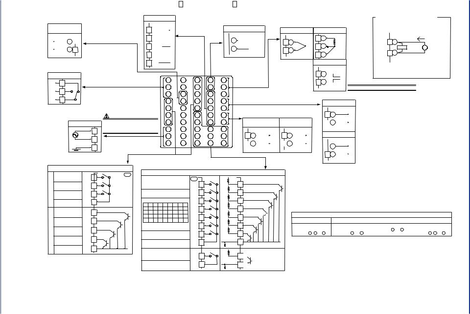
■ UT550 Standard Type (Model: UT550-0 |
or UT550-3 |
), Single-loop Control |
|
||||||||
*Wiring can only |
be carried out for controllers with |
RS-485 communication |
|
* Wiring can only be carried out for |
PV input * Not configured at factory before shipment |
Receiving 4-20 mA DC Current |
|||||
24 V DC sensor power supply. |
|
|
|
* Wiring can only be carried out |
Signals with the Controller |
||||||
|
|
|
|
for controllers with communication |
controllers with remote input. |
See "2. Initial Settings". |
|||||
24 V DC sensor |
|
|
|
|
. |
||||||
23 |
|
|
|
functions. |
|
Remote input |
|
|
* When receiving 4-20 mA DC current signals, |
||
power supply |
|
SDB(+) |
|
|
|
TC input |
RTD input |
||||
|
|
|
Maximum baud rate: 9600 bps |
|
set the PV input type to 1-5 V DC (setpoint “41”). |
||||||
|
|
|
|
|
|||||||
|
|
+ |
|
|
|
|
|
|
|
43 |
|
|
|||
21.6-28.0VDC |
|
|
|||||
|
|
|
|
|
|||
(30 mA DC max.) |
- |
44 |
|
|
|||
|
|
|
Note: Select this option from |
||||
Control output |
|||||||
the OT1 parameter. |
|||||||
|
|
|
|
|
|
||
Relay contact output |
*Time proportional PID relay contact |
||||||
|
|||||||
24
25 26
27
SDA(-) 
RDB(+)
RDA(-) 
SG
|
1 |
output is configured at factory |
|
1 |
41 |
||
NC |
before shipment. |
|
|
|
|||
|
|
2 |
42 |
||||
|
|
|
|
|
|
||
NO |
2 |
|
|
|
|
3 |
43 |
|
|
|
|
|
|
||
COM |
3 |
|
|
|
|
4 |
44 |
|
|
|
|
|
|
||
Contact rating: 250 V AC, 3 A |
|
|
|
5 |
45 |
||
|
|
30 V DC, 3 A (resistance load) |
|
|
|||
|
|
|
|
|
|
||
|
|
Power supply |
CAUTION |
|
6 |
46 |
|
|
|
|
|
|
|||
|
|
Before carrying out wiring, turn off the power |
|
|
|||
|
|
Power supply |
7 |
47 |
|||
|
|
to the controller and check that cables to be |
|||||
|
|
|
|
||||
|
|
L |
8 |
connected are not alive with a tester or the like |
8 |
48 |
|
|
|
because there is a possibility of electric shock. |
|||||
|
|
|
|
|
|||
|
|
N |
9 |
|
|
9 |
49 |
|
|
|
|
|
|
||
|
|
|
|
|
10 |
50 |
|
|
|
|
|
|
|
||
|
|
|
10 |
|
|
|
|
|
|
Allowable range: 100-240 V AC ( 10%) |
|
|
|
||
|
|
|
(free voltage) |
|
|
|
|
|
|
|
50/60 Hz shared |
* The functionality of a contact input |
|||
|
|
|
|
|
|||
|
|
External contact outputs |
input registration parameter. |
||||
|
|
|
|
|
|||
21 |
+ |
|
|
Specify in a range of |
|||
|
|
1-5 V DC, 0-2 V DC, |
|
22 |
- |
or 0-10 V DC. |
|
|
|
||
|
|
Default: 1-5 V DC |
|
|
|
||
31 |
21 |
11 |
32 |
22 |
12 |
33 |
23 |
13 |
|
11 |
A |
12 |
+ |
b |
|
12 |
|
13 |
- |
|
|
13 |
B |
|
|
mV/V input |
12+ 
13- 
 NOTE
NOTE
12 |
+ |
|
250 Ω 4-20mA |
13 |
- |
Note: Connecting a 250 Ω resistor to the terminals is |
|
optional. |
|
Model: X010-250-2 (resistor with M3.5 crimp-on terminal |
|
lugs) |
|
Installation category (overvoltage category): II (IEC1010-1)
34 |
24 |
14 |
35 |
25 |
15 |
36 |
26 |
16 |
37 |
27 |
17 |
38 |
28 |
18 |
39 |
29 |
19 |
40 |
30 |
20 |
Retransmission output 1* |
* Factory-set to “PV retransmission.” |
|
|
|
|
|
|
|
Note: Select this option from the OT1 parameter. |
|
|
|
|
|
|
|||||
Control output |
* Retransmission output 2 is available |
|
|
|
|
|
|
||||||||||
only when “relay” is selected as the |
14 |
+ |
|
|
|||||||||||||
|
|
|
|
|
|
|
|
||||||||||
|
|
|
|
|
|
type of control output. |
|
|
4-20 or |
||||||||
Continuous/voltage |
Retransmission |
|
|
|
|
||||||||||||
|
|
|
- |
0-20 mA DC |
|||||||||||||
|
|
|
pulse output |
|
|
output |
2* |
|
|
15 |
|
|
|||||
|
|
|
|
|
|
|
|
Default: Unspecified |
|
|
|
Default: 4-20 mA DC |
|||||
|
|
|
|
|
|
|
|
|
|
|
|||||||
|
|
|
|
|
|
|
|
retransmission type |
|
|
|
||||||
|
|
|
|
|
|
|
|
|
|
|
|
|
|
||||
16 |
+ |
|
|
|
16 |
+ |
|
|
|
15 V DC sensor power supply* |
|||||||
0-20mADC, |
|
0-20mADC, |
|
|
|
|
|
|
|||||||||
|
|
|
|
4-20mADC |
|
|
|
|
|
|
|
|
|
||||
|
|
|
|
|
|
|
4-20mADC |
|
|
|
|
|
|
||||
17 |
- |
Voltage pulse (12 V) |
17 |
- |
|
|
|
|
|
|
|||||||
|
|
|
|
|
|
|
14 |
+ |
14.5-18.0 V DC |
||||||||
|
|
|
|
|
|
|
|
Default: 4-20 mA DC |
|
||||||||
|
|
|
|
|
|
|
|
|
|
|
- |
(21 mA DC max.) |
|||||
|
|
|
|
|
|
|
|
|
|
|
|
15 |
|
|
|||
|
|
|
|
|
|
|
|
|
|
|
|
|
|
||||
Load resistance: 600 |
Ω or less |
*Retransmission output 1 is not available if a 15 V DC sensor power supply is used.
can be varied by changing the setting of the contact
Alarm 1 output |
DO1 |
6 |
|
|
Relay |
Alarm 2 output |
DO2 |
5 |
|
|
||||
|
Alarm 3 output |
DO3 |
4 |
|
|
|
|||
|
Common |
COM |
7 |
|
|
|
|||
|
Alarm 4 output |
DO4 34 |
||
Transistor |
No function |
DO5 |
33 |
|
|
||||
No function |
DO6 |
32 |
||
|
||||
|
|
|||
|
FAIL output |
DO7 |
31 |
|
|
(ON when normal) |
|||
|
|
|||
|
|
|
||
|
Common |
COM |
35 |
|
|
|
|||
Relay contact rating: 240 V AC, 1 A |
|
|||
|
30 V DC, 1 A (resistance load) |
|||
Transistor contact rating: 24 V DC, 50 mA |
||||
UT
AUTO when DI1=ON
MAN when DI1=OFF
STOP when DI2=ON
RUN when DI2=OFF
When switching among target setpoints 1 to 8: 1.SP2.SP 3.SP4.SP 5.SP 6.SP7.SP 8.SP DI3 ON OFF ON OFF ON OFF ON OFF DI4 OFF ON ON OFF OFF ON ON OFF DI5 OFF OFF OFF ON ON ON ON OFF DI6 OFF OFF OFF OFF OFF OFF OFF ON
* If all of the contact inputs are set to OFF, the controller uses the immediately preceding target setpoint.
No function
Common
Remote when DI8=ON
Local when DI8=OFF
Common
External contact |
|
UT |
Contact |
|
|
DI1 |
19 |
DI2 |
18 |
DI3 |
40 |
DI4 |
39 |
DI5 |
38 |
DI6 |
37 |
DI7 |
36 |
COM 20 |
|
DI8 |
28 |
COM 30 |
|
inputs
+5V DI1 +5V DI2 +5V
DI3 +5V
DI4 +5V
DI5 +5V
DI6 +5V
DI7 COM
+5V DI8
COM
Transistor contact
19
18
40 39 38
37
36
20
28  30
30 
*OT1 is a setup parameter.
You can change the settings of the parameter OT1 to change the control output type.
See "2. Initial Settings". |
|
. |
|
|
|
|
|
Correspondence between parameter OT1 and control output types |
|
||||||
OT1=0 (factory-set default) |
OT1=1 |
|
OT1=2 |
|
|
|
OT1=3 |
|
|
|
|
||||
Time proportional control |
Time proportional control |
|
Current output |
|
|
|
On-off control |
Relay output |
Voltage pulse output |
|
(terminals 16 and |
17 |
) |
|
Relay output |
(terminals 1 , 2 and 3 ) |
(terminals 16 and 17 ) |
|
|
|
|
|
(terminals 1 , 2 and 3 ) |
|
|
|
|
|
|
|
|
Contact rating: 12 V DC, 10 mA or more
Note: External Contact Input If the power is turned on when the external contact input is OFF, the mode (SPN, R/L, or A/M) existing before the power is turned off will be continued. (except for RUN/STOP)
<Toc>
> Installation .1 <
14-1

00-2000 31, .Mar Edition: 1st 41E-05D01C02 IM
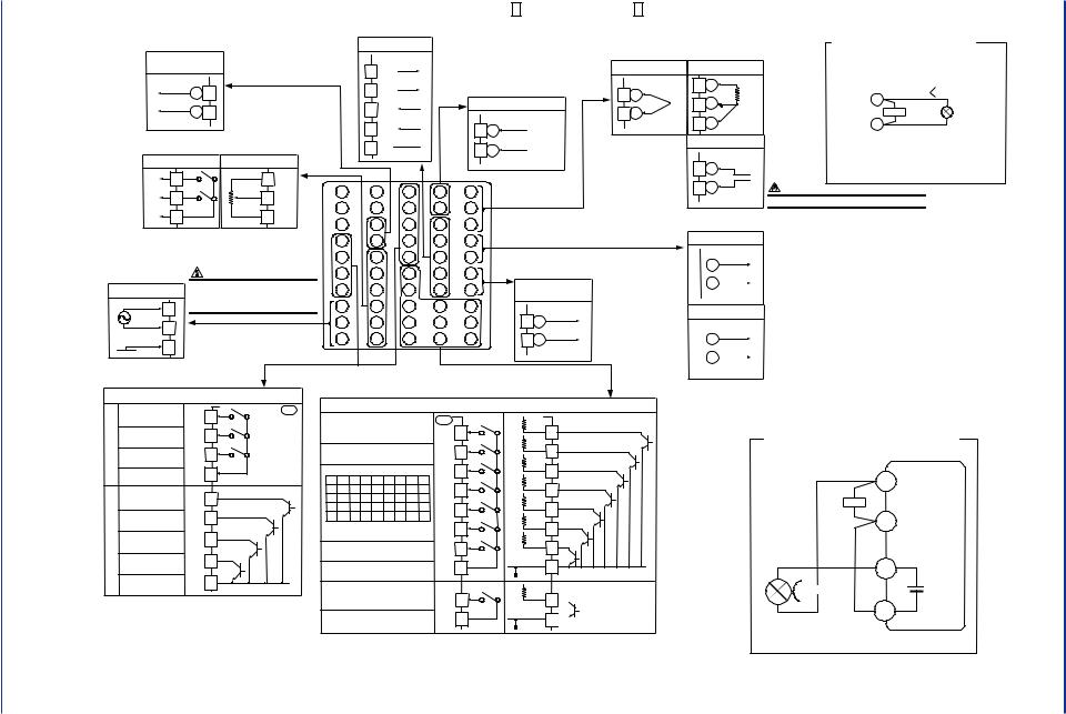
■ UT550 Heating/Cooling Type (Model: UT550-2 |
), Single-loop Heating/Cooling Control |
Cooling-side control |
Cooling-side control |
|
|||||
output |
|
|
output |
Note: Select this option from |
|||
|
|
|
|
|
|
||
Continuous/voltage pulse output |
Relay contact output |
the OT1 parameter. |
|||||
|
|
|
|
NC |
48 |
*Time proportional PID |
|
|
|
|
|
relay contact output is |
|||
|
|
+ |
46 |
|
|
||
|
0-20 mA DC |
|
49 |
configured at factory |
|||
|
|
|
NO |
||||
|
4-20 mA DC, |
|
|
before shipment. |
|
||
voltage pulse (12 V) |
- |
47 |
|
|
|
||
|
|
COM |
50 |
|
|
||
|
|
|
|
|
|
||
|
|
|
|
Contact rating: 250 V AC, 3 A |
|
||
|
|
|
|
|
30 V DC, 3 A (resistance load) |
|
|
Heating-side control output |
|
|
|||||
Relay contact output |
Note: Select this option from the |
|
|||||
|
OT1 parameter. |
|
|
||||
|
|
|
|
|
|
1 |
|
NC |
1 |
|
|
*Time proportional PID relay contact |
|||
|
|
|
|||||
|
2 |
|
|
output is configured at factory |
2 |
||
NO |
|
|
before shipment. |
|
3 |
||
|
|
|
|
|
|||
|
|
|
|
|
|
|
|
RS-485 communication
23 SDB(+) 
24 SDA(-) 
25 RDB(+)
*Wiring can only be carried out for controllers with communication functions.
Maximum baud rate: 9600 bps
* Wiring can only be carried out for controllers with remote input. Remote input
26 RDA(-) |
|
21 |
+ |
Specify in a range of |
|
|
|
|
|
|
|
|
|
|
22 |
|
1-5 V DC, 0-2 V DC, |
27 |
SG |
|
- |
or 0-10 V DC. |
|
|
|
||||
|
|
|
|
|
Default: 1-5 V DC |
41 |
31 |
21 |
11 |
|
|
42 |
32 |
22 |
12 |
|
|
43 |
33 |
23 |
13 |
|
|
PV input |
* Not configured at factory before shipment |
Receiving 4-20 mA DC Current |
|
|
See "2. Initial Settings". |
Signals with the Controller |
|
TC input |
RTD input |
* When receiving 4-20 mA DC current signals, |
|
set the PV input type to 1-5 V DC (setpoint “41”). |
|||
|
11 |
A |
|
12 |
+ |
b |
|
|
12 |
|
|
13 |
- |
|
|
|
|
|
|
|
13 |
B |
|
|
|
mV/V input |
|
|
12 |
+ |
|
|
13 |
- |
NOTE |
12 |
+ |
|
250 Ω 4-20mA |
13 |
- |
Note: Connecting a 250 Ω resistor to the terminals is |
|
optional. |
|
Model: X010-250-2 (resistor with M3.5 crimp-on terminal |
|
lugs) |
|
Installation category (overvoltage category): II (IEC1010-1)
COM |
3 |
|
|
Contact rating: 250 V AC, 3 A |
|||
|
30 V DC, 3 A (resistance load) |
||
Power supply |
CAUTION |
||
|
Power supply |
||
|
Before carrying out wiring, turn off the power |
||
|
|
|
|
|
L |
8 |
to the controller and check that cables to be |
|
|
connected are not alive with a tester or the like |
|
|
N |
|
because there is a possibility of electric shock. |
|
9 |
|
|
|
|
|
|
|
|
10 |
|
Allowable range: 100-240 V AC ( 10%) |
|||
|
|
(free voltage) |
|
|
|
50/60 Hz shared |
|
|
|
External contact outputs |
|
4 |
44 |
34 |
24 |
14 |
5 |
45 |
35 |
25 |
15 |
6 |
46 |
36 |
26 |
16 |
7 |
47 |
37 |
27 |
17 |
8 |
48 |
38 |
28 |
18 |
9 |
49 |
39 |
29 |
19 |
10 |
50 |
40 |
30 |
20 |
|
|
|
|
|
|
|
|
|
|
|
|
Retransmission output 1* |
|||||||
|
|
|
|
|
Note: Select this option from the OT1 parameter. |
|
|
|
|
|
|
|
|
||||||
Heating-side |
* Retransmission output 2 is available |
|
|
|
|
|
|
|
|
||||||||||
only when “relay” is selected as the |
14 |
+ |
|
|
|
||||||||||||||
control output |
type of control output. |
|
|
|
4-20 or |
||||||||||||||
|
|
|
|
|
|
|
|
||||||||||||
Continuous/voltage |
Retransmission |
|
|
|
|
- |
|
0-20 mA DC |
|||||||||||
|
|
pulse output |
|
|
|
output |
2* |
|
|
15 |
|
|
|
||||||
|
|
|
|
|
|
|
|
|
|
|
|
|
|
||||||
|
|
|
|
|
|
|
|
Default: Unspecified |
|
|
|
|
Default: 4-20 mA DC |
||||||
|
|
|
|
|
|
|
|
retransmission type |
15 V DC sensor power supply* |
||||||||||
16 |
+ |
|
|
|
16 |
+ |
|
|
|
|
|
|
|
|
|
|
|
||
0-20mADC, |
|
|
|
|
|
|
|
|
|
|
|
|
|||||||
|
0-20mADC, |
|
|
|
|
|
|
|
|
||||||||||
|
|
|
4-20mADC |
|
|
|
|
|
|
|
|
|
|
|
|
||||
|
|
|
|
|
|
|
4-20mADC |
|
|
|
|
|
|
|
|
||||
17 |
- |
Voltage pulse (12 V) |
17 |
- |
|
|
|
|
|
|
|
|
|||||||
|
|
|
|
|
|
14 |
+ |
|
|
|
|||||||||
|
|
|
|
|
|
|
|
Default: 4-20 mA DC |
|
14.5-18.0 V DC |
|||||||||
|
|
|
|
|
|
|
|
|
|
|
|
|
|
||||||
|
|
|
|
|
|
|
|
|
|
|
|
- |
|
(21 mA DC max.) |
|||||
|
|
|
|
|
|
|
|
|
|
|
|
|
15 |
|
|
|
|||
|
|
|
|
|
|
|
|
|
|
|
|
|
|
|
|
|
|
|
|
* The functionality of a contact input can be varied by changing the setting of the contact input registration parameter.
* Factory-set to “PV retransmission.”
Load resistance: 600 Ω or less
* Retransmission output 1 is not available if a 15 V DC sensor power supply is used.
Relay
Alarm 1 output
Alarm 2 output
Alarm 3 output
Common
DO1 |
UT |
|
6 |
||
|
||
DO2 |
5 |
|
DO3 |
4 |
|
|
||
COM |
7 |
|
|
|
Alarm 4 output |
DO4 |
34 |
|
|
|
|
|
|
|
|
|
|
|
|
|
|
|
|
|
|
|
|
|
|
|
|
|
|
|
|
|
|
|
|
|
|
|
|
|
|
|
|
|
Transistor |
No function |
DO5 |
33 |
|
|
|
|
|
|
|
|
|
|
|
|
|
|
|
|
|
|
|
|
|
|
||||
|
No function |
DO6 |
32 |
|
|
|
|
|
|
|
|
|
|
|
|
FAIL output |
|
|
|
|
|
|
|
|
|
|
|
|
|
|
(ON when normal) |
DO7 |
31 |
|
|
|
|
|
|
|
|
|
|
|
|
|
|
|
|
|
|
|
|
|
|
|
|
||
|
COM |
35 |
|
|
|
|
|
|
|
|
|
|
|
|
|
Common |
|
|
|
|
|
|
|
|
|
|
|
||
|
|
|
|
|
|
|
|
|
|
|
|
|||
|
|
|
|
|
|
|
|
|
|
|
|
|||
|
|
|
|
|
|
|
|
|
|
|
|
|
||
Relay contact rating: 240 V AC, 1 A |
|
|
|
|
|
|
|
|
|
|
|
|
||
|
30 V DC, 1 A (resistance load) |
|||||||||||||
Transistor contact rating: 24 V DC, 50 mA |
||||||||||||||
* OT1 is a setup parameter. |
|
|
|
|
|
|
|
|
|
|
|
|
||
You can change the settings of the parameter OT1 to |
||||||||||||||
change the control output type. |
||||||||||||||
AUTO when DI1=ON
MAN when DI1=OFF
STOP when DI2=ON
RUN when DI2=OFF
When switching among target setpoints 1 to 8: 1.SP 2.SP 3.SP 4.SP 5.SP 6.SP7.SP 8.SP DI3 ON OFF ON OFF ON OFF ON OFF DI4 OFF ON ON OFF OFF ON ON OFF DI5 OFF OFF OFF ON ON ON ON OFF DI6 OFF OFF OFF OFF OFF OFF OFF ON
* If all of the contact inputs are set to OFF, the controller uses the immediately preceding target setpoint.
No function
Common
Remote when DI8=ON
Local when DI8=OFF
Common
External contact |
|
UT |
Contact |
|
|
DI1 |
19 |
|
|
DI2 |
18 |
DI3 |
40 |
|
|
DI4 |
39 |
|
|
DI5 |
38 |
DI6 |
37 |
DI7 |
36 |
COM 20 |
|
DI8 |
28 |
COM 30 |
|
inputs
+5V DI1 +5V DI2 +5V
DI3 +5V
DI4 +5V
DI5 +5V
DI6 +5V
DI7 COM
+5V DI8
COM
Transistor contact
19
18
40
39
38
37
36
20
28  30
30 
Contact rating: 12 V DC, 10 mA or more
Note: External Contact Input If the power is turned on when the external contact input is OFF, the mode (SPN, R/L, or A/M) existing before the power is turned off will be continued. (except for RUN/STOP)
See "2. Initial Settings".
|
|
Correspondence between parameter OT1 and heating side output types/cooling side output types |
|
|
|||||
OT1=4 (factory-set default) |
OT1=5 |
OT1=6 |
OT1=7 |
OT1=8 |
OT1=9 |
|
OT1=10 |
|
|
Heating side: Relay output |
Heating side: Voltage pulse output |
Heating side: Current output |
Heating side: Relay output |
Heating side: Voltage pulse output |
Heating side: Current output |
|
Heating side: Relay output |
||
(terminals 1 , 2 and 3 ) |
(terminals 16 and 17 ) |
(terminals 16 and 17 ) |
(terminals 1 , 2 and 3 ) |
(terminals 16 and 17 ) |
(terminals 16 and 17 |
) |
(terminals 1 , |
2 and |
3 ) |
Cooling side: Relay output |
Cooling side: Relay output |
Cooling side: Relay output |
Cooling side: Voltage pulse output |
Cooling side: Voltage pulse output |
Cooling side: Voltage pulse output |
Cooling side: Current output |
|||
(terminals 48 , 49 and 50 ) |
(terminals 48 , 49 and 50 ) |
(terminals 48 , 49 and 50 ) |
(terminals 46 and 47 ) |
(terminals 46 and 47 ) |
(terminals 46 and 47 |
) |
(terminals |
46 and |
47 ) |
The types of control output, “relay output” and “voltage pulse output” shown in the table above refer to those of time proportional control. |
|
|
|
|
|
||||
To change to a relay output for on-off control, select “Relay Terminals” and change the setpoint of the proportional band to “0.” |
|
|
|
|
|
||||
OT1=11 |
|
Heating side: Voltage pulse output |
|
(terminals 16 |
and 17 ) |
Cooling side: Current output |
|
(terminals 46 |
and 47 ) |
OT1=12 |
|
Heating side: Current output |
|
(terminals |
16 and 17 ) |
Cooling side: Current output |
|
(terminals |
46 and 47 ) |
<Toc>
> Installation .1 <
15-1
00-2000 31, .Mar Edition: 1st 41E-05D01C02 IM
■
UT550 Position Proportional Type (Model: UT550-1 |
or UT550-4 |
), Single-loop Position Proportional Control |
*Wiring can only be carried out for controllers with 24 V |
|||||||
|
DC sensor power supply. |
|
|
||||
|
24 V DC sensor |
|
|
|
|||
|
power supply |
|
|
|
|||
21.6-28.0VDC |
+ |
43 |
|
|
|
||
|
|
|
|
|
|||
(30 mA DC max.) |
- |
44 |
|
|
|
||
|
|
|
|
|
|
||
Position proportional control output |
|
||||||
Relay contact output |
Feedback input |
|
|||||
|
H |
48 |
|
|
0% |
47 |
|
(Direct) |
|
|
|
|
|||
|
|
|
|
|
|
||
|
L |
49 |
|
|
|
46 |
1 |
|
|
|
|
|
|||
(Reverse) |
|
|
|
|
|||
|
|
|
|
|
2 |
||
|
|
50 |
|
|
|
45 |
|
COM |
|
|
100% |
3 |
|||
|
|
|
|
|
|
||
|
|
|
|
|
|
|
|
Contact rating: 250 V AC, 3 A |
Resistance: 100 to 2.5 k |
|
|||||
30 V DC, 3 A (resistance load) |
|
|
4 |
||||
|
|
|
|
|
|
|
|
|
|
|
|
|
|
|
5 |
Power supply |
|
|
CAUTION |
|
6 |
||
|
Before carrying out wiring, turn off the power |
|
|||||
Power supply |
|
7 |
|||||
|
to the controller and check that cables to be |
||||||
L |
|
|
connected are not alive with a tester or the like |
8 |
|||
8 |
|
because there is a possibility of electric shock. |
|||||
|
|
||||||
|
|
|
|||||
N |
9 |
|
|
|
|
|
9 |
|
|
|
|
|
|
|
|
|
10 |
|
|
|
|
10 |
|
|
|
|
|
|
|
||
RS-485 communication |
* Wiring can only be carried out |
||||||||
for controllers with communication |
|||||||||
|
|
|
|||||||
|
|
|
functions. |
|
|
|
|
||
23 SDB(+) |
Maximum baud rate: 9600 bps |
||||||||
24 |
|
|
|
* Wiring can only be carried out for |
|||||
SDA(-) |
|
controllers with remote input. |
|||||||
25 RDB(+) |
|
|
Remote input |
|
|||||
|
|
|
|
|
|
||||
26 |
RDA(-) |
|
21 |
+ |
Specify in a range of |
||||
|
|
|
|
||||||
|
|
|
|
|
|
||||
|
|
|
|
|
|
1-5 V DC, 0-2 V DC, |
|||
27 |
|
SG |
|
22 |
- |
or 0-10 V DC. |
|
||
|
|
|
|
|
|||||
|
|
|
|
|
|
|
|||
|
|
|
|
|
|
Default: 1-5 V DC |
|||
41 |
31 |
21 |
11 |
|
|
|
|
||
42 |
32 |
22 |
12 |
|
|
|
|
||
43 |
33 |
23 |
13 |
|
|
|
|
||
44 |
34 |
24 |
14 |
|
|
|
|
||
45 |
35 |
25 |
15 |
|
|
|
|
||
46 |
36 |
26 |
16 |
|
|
|
|
||
47 |
37 |
27 |
17 |
|
Retransmission |
||||
|
|
output 2 |
|||||||
48 |
38 |
28 |
18 |
|
|
||||
|
|
Default: Unspecified |
|||||||
|
|
|
|
|
|
|
retransmission type |
||
49 |
39 |
29 |
19 |
|
16 |
+ |
0-20mADC, |
||
|
|
|
|
|
|
|
|
||
50 |
40 |
30 |
20 |
|
17 |
- |
4-20mADC |
||
|
|
||||||||
|
|
|
Default: 4-20 mA DC |
|
Allowable range: 100-240 V AC ( 10%) |
||||
|
||||
|
|
(free voltage) |
|
|
|
|
50/60 Hz shared |
* The functionality of a contact input can be varied by changing the setting of the contact |
|
|
|
|
||
|
|
External contact outputs |
input registration parameter. |
|
|
|
|
||
PV input |
* Not configured at factory before shipment |
||
|
See "2. Initial Settings". |
|
|
TC input |
RTD input |
|
|
12 + |
11 |
A |
|
|
b |
|
|
13 - |
12 |
|
|
|
|
|
|
|
13 |
B |
|
|
mV/V input |
|
|
|
12 |
+ |
|
|
13 |
- |
NOTE |
|
|
||
Receiving 4-20 mA DC Current |
|||||
Signals with the Controller |
|||||
* When receiving 4-20 mA DC current signals, |
|||||
set the PV input type to 1-5 V DC (setpoint “41”). |
|||||
|
|
|
+ |
|
|
|
12 |
|
|
||
|
|
|
250 Ω 4-20mA |
||
|
|
|
|||
|
|
|
- |
|
|
|
13 |
|
|
||
|
|
|
|
|
|
|
|
|
|
|
|
Note: Connecting a 250 Ω resistor to the terminals is |
|||||
optional. |
|||||
Model: X010-250-2 (resistor with M3.5 crimp-on terminal |
|||||
lugs) |
|
|
|
||
Installation category (overvoltage category): II (IEC1010-1)
Retransmission output 1 |
* PV retransmission is configured at factory |
||||||||
before shipment. |
|
||||||||
|
|
|
|
|
|
|
|
|
|
|
|
|
+ |
|
|
|
|
|
|
|
14 |
|
4-20 mA DC, |
|
|
||||
|
|
|
|
|
|
|
|
||
|
|
|
|
|
|
|
|
||
|
|
|
|
- |
|
0-20 mA DC |
|
|
|
|
15 |
|
|
|
|
Load resistance: 600 |
Ω or less |
||
|
|
|
|
Default: 4-20 mA DC |
|||||
|
|
|
|
||||||
|
|
|
|
|
|
||||
15 V DC sensor power supply |
* If 15 V DC sensor power supply is used, |
||||||||
|
|
|
|
|
|
|
|
retransmission output 1 cannot be used. |
|
|
|
|
|
|
|
|
|
|
|
|
14 |
+ |
|
14.5-18.0VDC |
|
|
|||
|
15 |
- |
|
(21 mA DC max.) |
|
|
|||
|
|
|
|
|
|
||||
|
|
|
|
|
|
||||
|
|
|
|
|
|
|
|
|
|
|
|
|
|
|
|
|
|
|
|
Relay
Alarm 1 output
Alarm 2 output
Alarm 3 output
Common
DO1 |
UT |
|
6 |
||
|
||
DO2 |
5 |
|
DO3 |
4 |
|
|
||
COM |
7 |
|
|
Alarm 4 output |
DO4 34 |
Transistor
No function
No function
FAIL output (ON when normal)
Common
DO5 |
33 |
DO6 |
32 |
|
|
DO7 |
31 |
|
|
COM |
35 |
|
Relay contact rating: 240 V AC, 1 A 30 V DC, 1 A (resistance load) Transistor contact rating: 24 V DC, 50 mA
AUTO when DI1=ON
MAN when DI1=OFF
STOP when DI2=ON
RUN when DI2=OFF
When switching among target setpoints 1 to 8: 1.SP 2.SP 3.SP 4.SP 5.SP 6.SP7.SP 8.SP DI3 ON OFF ON OFF ON OFF ON OFF DI4 OFF ON ON OFF OFF ON ON OFF DI5 OFF OFF OFF ON ON ON ON OFF DI6 OFF OFF OFF OFF OFF OFF OFF ON
* If all of the contact inputs are set to OFF, the controller uses the immediately preceding target setpoint.
No function
Common
Remote when DI8=ON
Local when DI8=OFF
Common
External contact |
|
UT |
Contact |
|
|
DI1 |
19 |
|
|
DI2 |
18 |
DI3 |
40 |
|
|
DI4 |
39 |
|
|
DI5 |
38 |
DI6 |
37 |
DI7 |
36 |
COM 20 |
|
DI8 |
28 |
COM 30 |
|
inputs
+5V DI1 +5V DI2 +5V
DI3 +5V
DI4 +5V
DI5 +5V
DI6 +5V
DI7 COM
+5V DI8
COM
Transistor contact
19
18
40
39
38
37
36
20
28  30
30 
*The following method of wiring is only possible when the controller is equipped with a 24 V DC sensor power supply.
24 V DC Power Supply Wired to Sensor in |
|||
Two-wire System Configuration |
|
||
|
12 |
|
|
External |
|
PV input |
|
resistor |
250 |
||
1-5 V DC |
|||
(Note) |
|
||
|
signal |
||
|
|
||
|
13 |
|
|
Two-wire |
|
|
|
transmitter |
43 |
|
|
|
|
||
|
|
Sensor power |
|
4-20mADC |
|
supply |
|
|
21.6- |
||
|
|
||
|
44 |
28.0 V DC |
|
|
|
||
Contact rating: 12 V DC, 10 mA or more |
Note: Connecting a 250 resistor to the terminals is optional. |
Note: External Contact Input |
Model: X010-250-2 (resistor with M3.5 crimp-on terminal lugs) |
|
|
If the power is turned on when the external contact input is OFF, the mode (SPN, R/L, or A/M) |
|
existing before the power is turned off will be continued. (except for RUN/STOP) |
|
<Toc>
> Installation .1 <
16-1
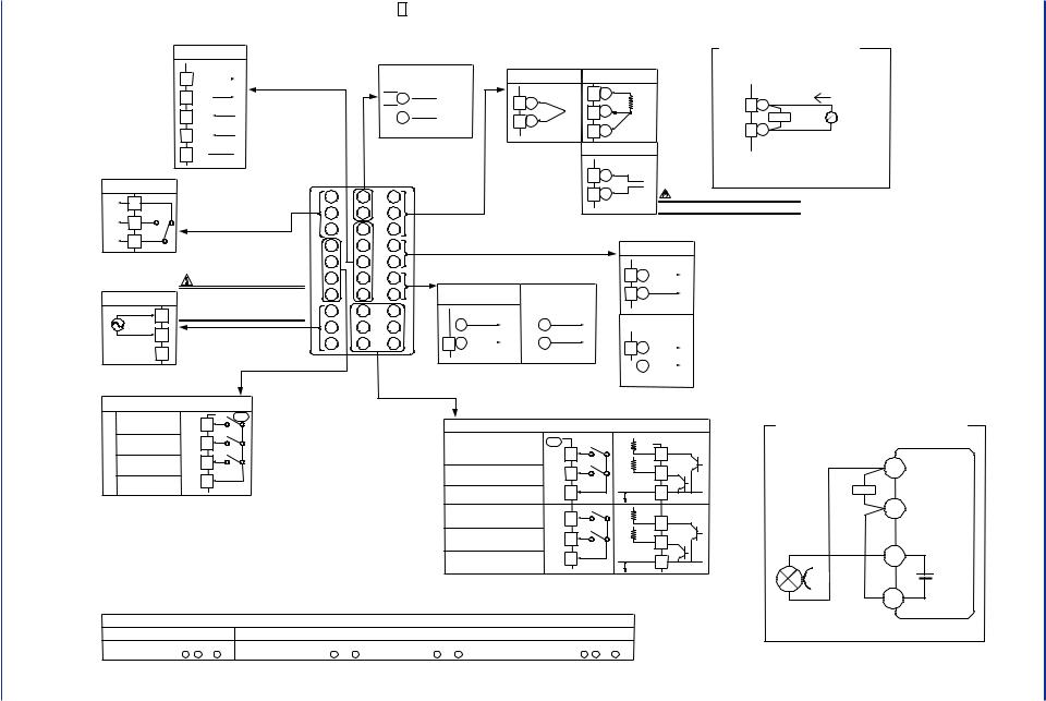
00-2000 31, .Mar Edition: 1st 41E-05D01C02 IM
■ UT520 Standard Type (Model: UT520-0 |
), Single-loop Control |
|
||||||||
RS-485 communication |
* Wiring can only be carried out |
* Wiring can only be carried out for |
PV input * Not configured at factory before shipment |
Receiving 4-20 mA DC Current |
||||||
for controllers with communication |
controllers with remote input. |
See "2. Initial Settings". |
Signals with the Controller |
|||||||
|
|
|
||||||||
23 SDB(+) |
|
|
functions. |
|
Remote input |
TC input |
RTD input |
* When receiving 4-20 mA DC current signals, |
||
|
|
Maximum baud rate: 9600 bps |
|
|
|
set the PV input type to 1-5 V DC (setpoint “41”). |
||||
|
|
|
|
|
|
|
||||
|
|
|
24 |
SDA(-) |
|
|
|
25 RDB(+) |
|
|
|
|
26 |
RDA(-) |
|
|
|
27 |
SG |
Control output |
|
|
||
Relay contact output |
Note: Select this option from the |
|||
|
1 |
|
|
OT1 parameter. |
NC |
|
*Time proportional PID relay contact |
||
|
2 |
|
output is configured at factory |
|
NO |
|
before shipment. |
||
|
|
|
||
COM |
3 |
|
|
|
Contact rating: 250 V AC, 3 A |
|
|||
|
|
30 V DC, 3 A (resistance load) |
||
Power supply |
|
CAUTION |
||
|
|
|||
Power supply |
Before carrying out wiring, turn off the power |
|||
to the controller and check that cables to be |
||||
|
L |
|
connected are not alive with a tester or the like |
|
|
8 |
because there is a possibility of electric shock. |
||
|
|
|||
|
N |
9 |
|
|
|
|
|
|
|
|
|
10 |
|
|
Allowable range: 100-240 V AC ( 10%) |
||||
|
|
(free voltage) |
||
|
|
50/60 Hz shared |
||
21
22
1 |
21 |
11 |
2 |
22 |
12 |
3 |
23 |
13 |
4 |
24 |
14 |
5 |
25 |
15 |
6 |
26 |
16 |
7 |
27 |
17 |
8 |
28 |
18 |
9 |
29 |
19 |
10 |
30 |
20 |

 +
+ 
 -
- 
Specify in a range of 1-5 V DC, 0-2 V DC, or 0-10 V DC.
Default: 1-5 V DC
|
11 |
A |
12 |
+ |
b |
|
12 |
|
13 |
- |
|
|
13 |
B |
|
mV/V input |
|
|
12 |
+ |
12 |
+ |
|
250 Ω 4-20mA |
13 |
- |
Note: Connecting a 250 Ω resistor to the terminals is |
|
optional. |
|
Model: X010-250-2 (resistor with M3.5 crimp-on terminal |
|
lugs) |
|
13 |
- |
NOTE |
|
|
Installation category (overvoltage category): II (IEC1010-1) |
Retransmission output 1*
|
|
|
Note: Select this option from the OT1 parameter. |
|||||||
Control output |
* Retransmission output 2 is available |
|||||||||
only when “relay” is selected as the |
||||||||||
|
|
|
||||||||
|
|
|
type of control output. |
|||||||
Continuous/voltage |
Retransmission |
|||||||||
|
pulse output |
|
|
|
|
output 2* |
|
|||
|
|
|
|
|
|
|
Default: Unspecified |
|||
|
|
|
|
|
|
|
retransmission type |
|||
16 |
+ |
0-20mADC, |
|
|
16 |
+ |
0-20mADC, |
|||
|
|
|
|
|
|
|
||||
|
|
4-20mADC |
|
|
|
|
|
4-20mADC |
||
17 |
- |
Voltage pulse (12 V) |
17 |
- |
||||||
|
|
|
|
|
||||||
|
|
|
|
|
|
|
Default: 4-20 mA DC |
|||
|
|
|
|
|
|
|
||||
|
|
|
|
|
|
|
||||
14 |
+ |
|
|
|||
4-20 or |
||||||
|
|
|
|
|||
15 |
- |
0-20 mA DC |
||||
|
|
|||||
|
|
|
Default: 4-20 mA DC |
|||
15 V DC sensor power supply* |
||||||
|
|
|
|
|
||
14 |
+ |
|
|
|||
14.5-18.0 V DC |
||||||
|
|
|
|
|||
|
|
|
- |
(21 mA DC max.) |
||
|
15 |
|
|
|||
|
|
|
|
|
|
|
*Factory-set to
“PV retransmission.”
Load resistance: 600 Ω or less
*Retransmission output 1 is not available if a
15 V DC sensor power
supply is used.
|
External contact outputs |
|||
|
Alarm 1 output |
DO1 |
UT |
|
|
6 |
|||
|
|
|
||
Relay |
Alarm 2 output |
DO2 |
5 |
|
Alarm 3 output |
DO3 |
4 |
||
|
||||
|
|
|||
|
Common |
COM |
7 |
|
|
|
|||
Relay contact rating: 240 V AC, 1 A |
||||
|
30 V DC, 1 A (resistance load) |
|||
Note: External Contact Input If the power is turned on when the external contact input is OFF, the mode (SPN, R/L, or A/M) existing before the power is turned off will be continued. (except for RUN/STOP)
*OT1 is a setup parameter.
You can change the settings of the parameter OT1 to change the control output type.
* The functionality of a contact input can be varied by changing the setting of |
||||||
the contact input registration parameter. |
|
|
|
|||
|
External contact inputs |
|
|
|||
|
UT |
Contact |
+5V |
Transistor contact |
||
|
|
|
|
|||
AUTO when DI1=ON |
|
|
DI1 |
|
||
DI1 |
19 |
+5V |
19 |
|||
MAN when DI1=OFF |
|
|||||
|
|
|
|
|||
|
|
|
DI2 |
|
||
STOP when DI2=ON |
DI2 |
18 |
|
18 |
||
|
|
|||||
RUN when DI2=OFF |
|
|
||||
|
|
|
COM |
|
||
|
COM |
20 |
|
20 |
||
Common |
|
|
||||
|
|
|
|
|||
No function |
|
|
+5V |
|
|
|
DI3 |
40 |
|
DI3 |
40 |
||
|
+5V |
|||||
|
|
|
|
|||
Remote when DI8=ON |
|
|
|
|
||
DI8 |
28 |
|
DI8 |
28 |
||
Local when DI8=OFF |
|
|||||
|
|
|
|
|||
|
|
|
|
|
||
Common |
COM 30 |
|
COM |
30 |
||
|
|
|||||
|
|
|
|
|||
|
Contact rating: 12 V DC, 10 mA or more |
|
||||
15 V DC Power Supply Wired to Sensor in Two-wire System Configuration
|
|
12 |
|
|
External |
|
PV input |
||
resistor |
100 |
|||
0.4-2.0 |
V DC |
|||
(Note) |
|
|||
|
signal |
|||
|
|
|||
|
|
13 |
|
|
Two-wire |
|
|
|
|
transmitter |
|
14 |
|
|
|
|
|
||
|
|
Sensor power |
||
4-20mADC |
|
|
supply |
|
|
|
14.5- |
||
|
|
|
||
|
|
18.0 V DC |
||
|
|
15 |
|
|
See "2. Initial Settings". |
|
|
|
|
|
|
|
|
|
Correspondence between parameter OT1 and control output types |
|
|
Note: Connecting a 100 resistor to the terminals is optional. |
||||
|
|
|
|
|
|
|
|
|
OT1=0 (factory-set default) |
OT1=1 |
|
OT1=2 |
|
|
OT1=3 |
|
Model: X010-100-2 (resistor with M3.5 crimp-on terminal lugs) |
Time proportional control |
Time proportional control |
|
Current output |
|
|
On-off control |
|
|
Relay output (terminals 1 , 2 and 3 ) |
Voltage pulse output (terminals 16 |
and 17 ) |
(terminals 16 and |
17 |
) |
Relay output (terminals 1 |
, |
2 and 3 ) |
|
|
|
|
|
|
|
|
|
<Toc>
> Installation .1 <
17-1

Blank Page
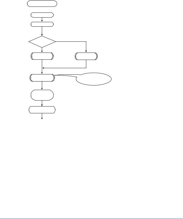
<Toc> |
< 2. Initial Settings > |
2-1 |
2.Initial Settings
This chapter describes examples of setting PV input types, control output types, and alarm types. Carrying out settings described herein allows you to perform basic control. Refer to examples of various settings to understand how to set parameters required. Refer to “5.1 Parameter Map” for an easy to understand explanation of setting various parameters. If you cannot remember how to carry out an operation during setting, press the  key for more than 3 seconds. This brings you to the display (operating display) that appears at power-on.
Setup Procedure
Power-on
 Set PV input.
  (Factory-set to “Unspecified.”)
See “2.2 Setting PV Input Type (Setting First at Power-on),” or “2.3 Changing PV Input Type.”
 Denotes a step that must always be followed.
 Denotes a step that should be followed as necessary.
Position |
No |
|
|
proportional |
|
|
|
controller? |
|
|
|
Yes |
|
|
|
Calibrate valve |
Set the control |
(Factory-set to “Time Proportional Relay Output.”) |
|
position. |
output. |
||
|
|||
|
See “2.4 Setting Control Output Type.” |
||
See “2.5 Calibrating Valve Position.” |
|
||
Initialize parameters.
See “2.6 Initializing Parameters.”
Set the alarm type and other setup
parameters.
Be sure to follow this
step whenever a chang of setting is made to the PV input type.
Set operating parameters.
Controller operation
The following explanation of operation for the UT550’s panel, shown in the figure, is the same as that of the UT520’s panel.
IM 05D01C02-41E 1st Edition: Mar. 31, 2000-00
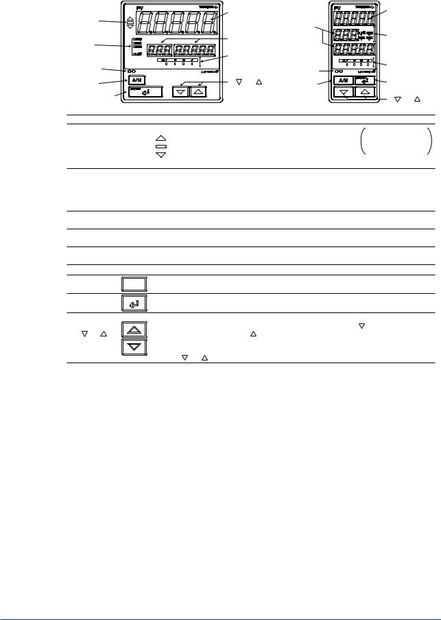
<Toc> |
< 2. Initial Settings > |
2-2 |
2.1Names and Functions of Front Panel Parts
1. Deviation |
|
|
4. Process |
5. Setpoint |
4. Process |
|||
monitor |
|
|
variable (PV) |
variable (PV) |
||||
|
|
display |
||||||
|
|
|
|
display |
|
display |
||
2. Status indicator |
|
|
5. Setpoint |
|
2. Status |
|||
|
|
|
indicator lamps |
|||||
lamps |
|
|
display |
|
|
|||
|
|
|
|
|
||||
3. Light-loader |
|
|
6. Alarm |
|
|
|
||
|
|
indicator |
3. Light-loader |
6. Alarm indicator |
||||
interface |
|
|
lamps |
|
interface |
lamps |
||
7. A/M key |
|
|
9. and |
keys |
7. A/M key |
8. SET/ENT |
||
8. SET/ENT key |
|
|
|
|
|
key |
||
|
|
|
|
|
9. and keys |
|||
|
|
|
|
|
|
|
||
|
Name of Part |
|
|
|
|
Function |
|
|
|
|
|
|
When lit, indicates the status of a deviation (PV - SP). |
The deviation display |
|||
|
Deviation monitor |
: Is lit (in orange) if a deviation exceeds the deviation display range. |
range can be changed |
|||||
1. |
: Is lit (in green) when a deviation is within the deviation display range. |
using the setup |
||||||
(for UT550 only) |
||||||||
|
: Is lit (in orange) if a deviation falls below the deviation display range. |
parameter “DVB”. |
||||||
|
|
|
|
|||||
|
|
|
|
|
||||
|
|
|
|
The deviation monitor goes off if any display other than the operating display or SELECT display is shown. |
||||
|
|
|
|
Is lit (in green) to indicate the status of operation or control. |
|
|||
|
Status indicator |
|
CAS: Not used in Single-loop Control. |
|
|
|
||
2. |
|
REM: Is lit when in remote mode. |
|
|
|
|||
lamps |
|
|
|
|
|
|||
|
|
|
MAN: Is lit when in manual mode. |
|
|
|
||
|
|
|
|
|
|
|
||
|
|
|
|
LP2: Not used in Single-loop Control. |
|
|
|
|
3. |
Light-loader interface |
Interface for an adapter cable used when setting and storing parameters from a PC. |
||||||
This requires an optional parameter setting tool. |
|
|
||||||
|
|
|
|
|
|
|||
4. |
Process variable (PV) |
Displays PV. |
|
|
|
|||
display |
|
|
Displays an error code (in red) if an error occurs. |
|
|
|||
|
|
|
|
|
||||
5. |
Setpoint display |
|
Displays a parameter symbol in 3-digit LED. |
|
|
|||
|
Displays the setpoint of a parameter in 5-digit LED. |
|
||||||
|
|
|
|
|
||||
6. |
Alarm indicator lamps |
If any of alarms 1 to 4 occurs, the respective alarm indicator lamp (AL1 to AL4) is lit (in orange). |
||||||
7. |
A/M key |
|
A/M |
Used to switch between the AUTO and MAN modes. Each time you press the key, it switches to the |
||||
|
AUTO or MAN mode alternately. |
|
|
|
||||
|
|
|
|
|
|
|
||
8. |
SET/ENT |
S E T / E N T |
Used to switch or register a parameter. Pressing the key for more than 3 seconds allows you to switch |
|||||
key |
|
|
between the operating display and the main menu for operating parameter setting display alternately. |
|||||
|
|
|
||||||
|
|
|
|
Used to change numerical values. On setting displays for various parameters, you can change target |
||||
|
|
|
|
setpoints, parameters, and output values (in manual operation). Pressing the |
key decreases a |
|||
9. |
and |
|
|
numerical value, while pressing the |
key causes it to increase. You can hold down a key to gradually |
|||
keys |
|
|
increase the speed of change. To change from the parameter setting (operating or setup) display to the |
|||||
|
|
|
||||||
menu or from the setup parameter setting display menu to operating parameter setting display menu, press the and keys simultaneously.
■ Setting of Main Parameters at the Factory before Shipment
|
Factory-shipped values |
Factory-shipped values |
Factory-shipped values for |
|
Item |
for standard type |
position proportional type |
||
for heating/cooling type controllers |
||||
|
controllers |
controllers |
||
|
|
|||
|
|
|
|
|
Remote input signal |
|
|
|
|
(only for controllers |
|
1 to 5 V DC (variable) |
|
|
with remote inputs) |
|
|
|
|
|
|
|
|
|
Control output |
Time proportional PID |
Heating side: Time proportional PID relay output (variable) |
Relay output (fixed) |
|
|
relay output (variable) |
Cooling side: Time proportional PID relay output (variable) |
||
|
|
|||
Control action |
Reverse action (variable) |
Not specified |
|
|
PID parameter |
|
P = 5.0%, I = 240 seconds, D = 60 seconds. |
|
|
Alarm output |
Alarm-1: PV high limit, Alarm-2: PV low limit, Alarm-3: PV high limit, Alarm-4: PV low limit |
|||
IM 05D01C02-41E 1st Edition: Mar. 31, 2000-00
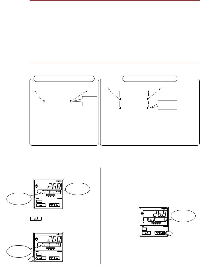
<Toc> |
< 2. Initial Settings > |
2-3 |
2.2Setting PV Input Type (Setting First at Power-on)
 NOTE
NOTE
•The controller displays an operating display when the power is turned on. The submenu “IN” appears at this point if the type of PV input has not been defined yet. In
this case, first press the  key once to display the parameter “IN1” for the PV input type, and use the
  key to display the input range code to use, then press the
  key to register it. Then, set the maximum value (RH1) and minimum value (RL1) of the PV input range (for voltage input, set the maximum value (SH1) and minimum value (SL1) of the PV input scale). See the operating procedure below for more details.
•The controller is configured to the default of each parameter at the factory before shipment.
First check these defaults listed in “5.2 Lists of Parameters”, and change their values if necessary.
Example of Temperature Input
-270.0°C |
|
|
|
|
1370.0°C |
|||||||
|
|
|
|
|
|
|
Instrument |
|
|
|
|
|
|
|
|
|
|
|
|
|
|
|
|
||
|
|
|
|
|
|
|
input range |
|
|
|
|
|
|
|
|
|
|
|
|
|
|
|
|
Set a range |
|
|
|
|
|
|
PV input range |
|
|
|
to be |
|||
|
|
|
|
|
|
|
|
|||||
|
|
|
|
|
|
|
|
|
|
|
controlled |
|
|
|
0.0°C |
|
800.0°C |
||||||||
|
|
|
|
|
||||||||
Minimum value of |
Maximum value of |
|
|
|||||||||
PV input range (RL1) |
PV input range (RH1) |
|
|
|||||||||
Parameters to be set for temperature input
1.PV input type (IN1): Set according to a sensor
2.Maximum value of PV input range (RH1): Set the maximum value of the range to be controlled.
3.Minimum value of PV input range (RL1): Set the minimum value of the range to be controlled.
Example of Voltage Input
1V |
2V |
|
|
4V |
5V |
|||||||
|
|
|
|
|
|
Instrument |
|
|
|
|
||
|
|
|
|
|
|
input range |
|
|
|
|
|
|
|
|
|
|
|
|
|
|
|
|
|
||
|
|
|
|
|
|
|
|
|
|
|
|
|
|
|
RL1 |
|
|
PV input range |
|
|
RH1 |
||||
|
|
|
|
|
|
|||||||
|
|
|
|
|
|
|
|
|
|
|
Set a range to |
|
|
|
|
|
|
|
|
|
|
|
|
||
|
|
|
|
|
PV input scale |
|
|
be controlled |
||||
|
|
|
|
|
|
|
|
|
||||
|
|
0.0m3/h |
|
50.0m3/h |
||||||||
|
Minimum value of |
Maximum value of |
||||||||||
PV input scale (SL1) |
PV input scale (SH1) |
|||||||||||
Parameters to be set for voltage input
1.PV input type (IN1): Set according to an input signal
2.Maximum value of PV input range (RH1): Set the maximum value of an input signal.
3.Minimum value of PV input range (RL1): Set the minimum value of an input signal.
4.Position of PV input decimal point (DP1): Set the position of the decimal point for PV input display.
5.Maximum value of PV input scale (SH1): Set the maximum value of the scale to be controlled.
6.Minimum value of PV input scale (SL1): Set the minimum value of the scale to be controlled.
The following operating procedure describes an example of setting a K-type thermocouple (-200.0 to 500.0˚C) and a measurement range of 0.0 to 200.0˚C.
1. Display view at power-on
PV
|
|
Displays |
|
REM |
submenu “IN”. |
|
CAS |
|
|
MAN |
|
Displays |
LP2 |
4 |
AL1 2 3 |
||
|
|
|
symbol “ST.S”. |
A/M |
|
SET/ENT
2. Press the SET/ENT key once to display the
parameter IN1 (PV input type). |
|
|
PV |
|
CAS |
|
REM |
|
MAN |
Displays |
LP2 |
AL1 2 3 4 |
|
|
|
parameter “IN1”. |
A/M |
|
|
3. Press the  or
or  key to display the required setpoint.
The figure below shows an example of setting a K-type thermocouple (-200.0°C to 500.0°C). See “Instrument Input Range Codes.”
PV
|
Blinks during |
REM |
change. |
CAS |
|
MAN |
|
LP2 |
4 |
AL1 2 3 |
|
A/M |
|
SET/ENT |
|
SET/ENT
IM 05D01C02-41E 1st Edition: Mar. 31, 2000-00
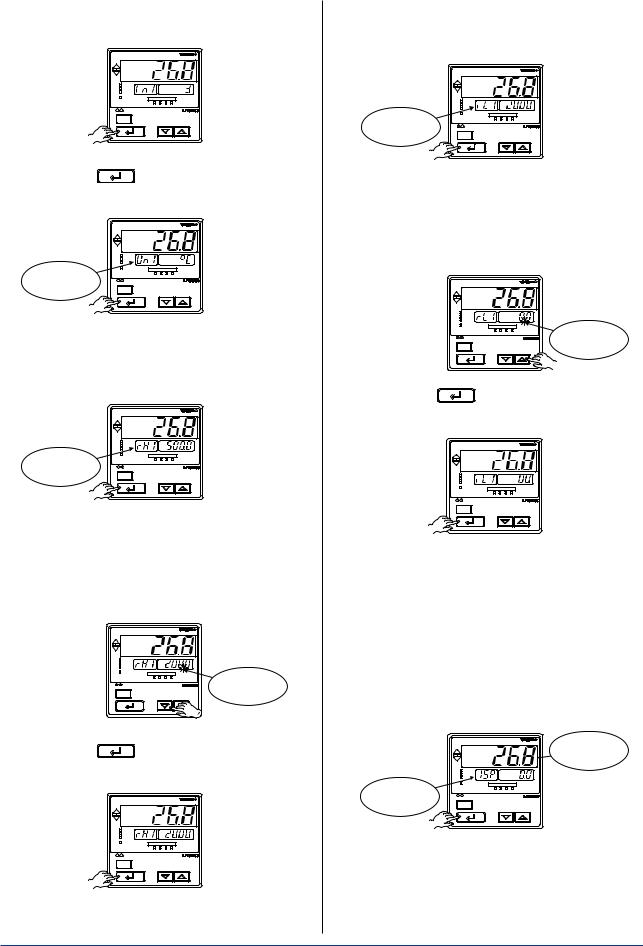
<Toc> |
< 2. Initial Settings > |
2-4 |
4. Press the  key once to register the setpoint.
PV
CAS
REM
MAN
LP2
AL1 2 3 4
|
A/M |
|
SET/ENT |
5. Press the SET/ENT |
key once to display the |
parameter “UN1” (PV input unit). |
|
|
PV |
|
CAS |
|
REM |
|
MAN |
Displays |
LP2 |
AL1 2 3 4 |
|
|
|
parameter “UN1”. |
A/M |
SET/ENT
6. Press the  key once to display the parameter “RH1” (maximum value of PV input range).
|
PV |
|
CAS |
|
REM |
|
MAN |
Displays |
LP2 |
AL1 2 3 4 |
|
parameter “RH1”. |
A/M |
|
|
|
SET/ENT |
7. Press the  or
or  key to display the required setpoint.
The figure below shows an example of setting the maximum value of the PV input range to 200.0°C.
PV
CAS |
|
REM |
|
MAN |
|
LP2 |
AL1 2 3 4 |
|
Blinks during |
A/M |
change. |
SET/ENT |
|
8. Press the SET/ENT key once to register the setpoint.
PV
CAS
REM
MAN
LP2
AL1 2 3 4
A/M
SET/ENT
9. Press the  key once to display the parameter “RL1” (minimum value of PV input range).
|
PV |
|
CAS |
|
REM |
|
MAN |
Displays |
LP2 |
AL1 2 3 4 |
|
parameter “RL1”. |
A/M |
|
SET/ENT |
10. Press the  or
or  key to display the required setpoint.
The figure below shows an example of setting the minimum value of the PV input range to 0.0°C.
PV
CAS |
|
REM |
|
MAN |
|
LP2 |
AL1 2 3 4 |
|
Blinks during |
A/M |
change. |
SET/ENT |
|
11. Press the SET/ENT key once to register the setpoint.
PV
CAS
REM
MAN
LP2
AL1 2 3 4
A/M
SET/ENT
If the type of input is voltage, also configure the PV Input Decimal Point Position (DP1), Maximum Value of PV Input Scale (SH1) and Minimum Value of PV Input Scale (SL1) parameters that follow this step.
12. Press the  key for more than 3 seconds. This returns you to the display shown at power-on (figure below).
PV
Displays PV
|
CAS |
|
REM |
|
MAN |
Displays |
LP2 |
AL1 2 3 4 |
|
target setpoint-1 |
|
“1.SP”. |
A/M |
SET/ENT |
The PV display in the figure above shows the error code for input burnout ( 


 ) if PV input wiring is not yet complete. The error code disappears when you wire the PV input terminals correctly.
IM 05D01C02-41E 1st Edition: Mar. 31, 2000-00

<Toc> |
|
|
|
< 2. Initial Settings > |
2-5 |
||
■ Instrument Input Range Codes |
|
|
|
|
|||
|
|
|
|
|
|
|
|
|
Input |
Type |
Instrument Input |
Instrument |
Measurement Accuracy |
|
|
|
Range Code |
Input Range |
|
|
|||
|
|
|
|
|
|
||
|
Unspecified |
|
OFF |
Set the data item PV Input Type “IN1” to the OFF option to leave the PV input |
|
||
|
|
type undefined. |
|
|
|
||
|
|
|
|
|
|
|
|
|
|
|
1 |
-270.0 to 1370.0°C |
|
|
|
|
|
|
-450.0 to 2500.0°F |
|
|
|
|
|
|
|
|
|
|
|
|
|
|
K |
2 |
-270.0 to 1000.0°C |
0.1% of instrument range 1 digit at 0°C or more |
|
|
|
|
-450.0 to 2300.0°F |
|
|
|||
|
|
|
3 |
-200.0 to 500.0°C |
0.2% 1 digit for temperatures below 0°C, |
|
|
|
|
|
-200.0 to 1000.0°F |
where the accuracy is: 2% of instrument range 1 |
|
||
|
|
|
|
|
|||
|
|
J |
4 |
-200.0 to 1200.0°C |
digit for temperatures below -200.0°C for a type-K |
|
|
|
|
thermocouple, or 1% of instrument range 1 digit for |
|
||||
|
|
-300.0 to 2300.0°F |
|
||||
|
|
|
5 |
-270.0 to 400.0°C |
temperatures below -200.0°C for a type-T thermocouple. |
|
|
|
|
|
|
|
|
||
|
|
T |
-450.0 to 750.0°F |
|
|
|
|
|
|
|
|
|
|
||
|
|
6 |
-000.0 to 400.0°C |
|
|
|
|
|
|
|
|
|
|
||
|
|
|
-200.0 to 750.0°F |
|
|
|
|
|
|
|
|
|
|
|
|
|
|
B |
7 |
-000.0 to 1800.0°C 0.15% of instrument range 1 digit at 400°C or more |
|
||
|
|
-032.0 to 3300°F |
5% of instrument range 1 digit at less than 400°C |
|
|||
|
|
|
|
|
|||
|
|
S |
8 |
-000.0 to 1700.0°C |
|
|
|
|
|
-032.0 to 3100°F |
0.15% of instrument range 1 digit |
|
|
||
|
|
|
|
|
|
||
|
|
R |
9 |
-000.0 to 1700.0°C |
|
|
|
|
|
-032.0 to 3100°F |
|
|
|
||
|
|
|
|
|
|
|
|
|
|
|
|
-200.0 to 1300.0°C |
0.1% of instrument range 1 digit |
|
|
|
Thermocouple |
N |
10 |
-300.0 to 2400.0°F |
0.25% of instrument range 1 digit for temperatures |
|
|
|
|
|
|
|
below 0°C |
|
|
|
|
E |
11 |
-270.0 to 1000.0°C |
|
|
|
|
|
-450.0 to 1800.0°F |
|
|
|
||
|
|
|
|
0.1% of instrument range 1 digit at 0°C or more |
|
|
|
|
|
L(DIN) |
12 |
-200.0 to 900.0°C |
|
|
|
|
|
-300.0 to 1600.0°F |
0.2% 1 digit for temperatures below 0°C, where the |
|
|||
|
|
|
|
|
|||
|
|
|
13 |
-200.0 to 400.0°C |
accuracy is: 1.5% of instrument range 1 digit for |
|
|
|
|
U(DIN) |
-300.0 to 750.0°F |
temperatures below -200.0°C for a type-E thermocouple. |
|
||
|
|
|
|
||||
|
|
14 |
-000.0 to 400.0°C |
|
|
|
|
|
|
|
|
|
|
||
|
|
|
-200.0 to 1000.0°F |
|
|
|
|
|
|
|
|
|
|
|
|
|
|
W |
15 |
-000.0 to 2300.0°C |
0.2% of instrument range 1 digit |
|
|
|
|
|
|
-032.0 to 4200°F |
|
|
|
|
|
Platinel 2 |
16 |
-000.0 to 1390.0°C |
0.1% of instrument range 1 digit |
|
|
|
|
-032.0 to 2500.0°F |
|
|
|||
|
|
PR20-40 |
17 |
-000.0 to 1900.0°C |
0.5% of instrument range 1 digit at 800°C or more |
|
|
|
|
-032.0 to 3400°F |
No accuracy is guaranteed at less than 800°C |
|
|
||
|
|
|
|
|
|
||
|
|
W97Re3- |
18 |
-000.0 to 2000.0°C |
0.2% of instrument range 1 digit |
|
|
|
|
W75Re25 |
|
-032.0 to 3600°F |
|
|
|
|
|
|
30 |
-200.0 to 500.0°C |
0.1% of instrument range 1 digit (Note 1) (Note 2) |
|
|
|
|
JPt100 |
|
-300.0 to 1000.0°F |
|
|
|
|
|
31 |
-150.00 to 150.00°C |
0.2% of instrument range 1 digit (Note 1) |
|
|
|
|
|
|
|
|
|||
|
|
|
|
-200.0 to 300.0°F |
|
|
|
|
RTD |
|
35 |
-200.0 to 850.0°C |
|
|
|
|
|
-300.0 to 1560.0°F |
0.1% of instrument range 1 digit (Note 1) (Note 2) |
|
|||
|
|
|
|
|
|||
|
|
Pt100 |
36 |
-200.0 to 500.0°C |
|||
|
|
|
|
|
|||
|
|
-300.0 to 1000.0°F |
|
|
|
||
|
|
|
|
|
|
|
|
|
|
|
37 |
-150.00 to 150.00°C |
0.2% of instrument range 1 digit (Note 1) |
|
|
|
|
|
|
0-200.0 to 300.0°F |
|
|
|
|
Standard |
0.4 to 2 V |
40 |
0.400 to 2.000 V |
|
|
|
|
signal |
1 to 5 V |
41 |
1.000 to 5.000 V |
0.1% of instrument range 1 digit |
|
|
|
|
0 to 2 V |
50 |
0.000 to 2.000 V |
|
|
|
|
|
Display range is scalable in a range of -19999 to 30000. |
|
||||
|
|
0 to 10 V |
51 |
0.00 to 10.00 V |
|
||
|
DC voltage |
Display span is 30000 or less. |
|
|
|||
|
-10 to 20 mV |
55 |
-10.00 to 20.00 mV |
|
|
||
|
|
0 to 100 mV |
56 |
0.0 to 100.0 mV |
|
|
|
*Performance in the standard operating conditions (at 23±2˚C, 55±10%RH, and 50/60 Hz power frequency) Note 1: The accuracy is ±0.3˚C of instrument range ±1 digit for a temperature range from 0˚C to 100˚C.
Note 2: The accuracy is ±0.5˚C of instrument range ±1 digit for a temperature range from -100˚C to 200˚C.
*To receive a 4-20 mA DC signal, select a standard signal of 1 to 5 V DC and connect it to a 250 resistor. This resistor is optional.
Model: X010-250-2 (resistor with M3.5 crimp-on terminal lugs)
IM 05D01C02-41E 1st Edition: Mar. 31, 2000-00

<Toc> |
< 2. Initial Settings > |
2-6 |
 NOTE
NOTE
The controller may automatically initialize the registered operating parameter setpoints if any change is made to the data item PV Input Type (IN1), Maximum Value of PV Input Range (RH1), Minimum Value of PV Input Range (RL1), PV Input Decimal Point Position (DP1), Maximum Value of PV Input Scale (SH1) or Minimum Value of PV Input Scale (SL1). After a change has been made to any of these data items, be sure to verify the registered operating parameter setpoints to ensure that they are correct. If any data item has been changed to its default, set it to a required value.
How to return to a menu
Simultaneously press both the  and
and  keys once during parameter setting. This lets you return to the parameter menu.
IM 05D01C02-41E 1st Edition: Mar. 31, 2000-00
Loading...