


V1000
Table of contents
 Loading...
YASKAWA AC Drive-V1000 Option
PROFINET
Technical Manual
TM
Type
To properly use the product, read this manual thoroughly and retain
for easy reference, inspection, and maintenance. Ensure the end user
receives this manual.
SI-EP3/V
MANUAL NO. SIEP YEACOM 06A


Table of Contents
1 PREFACE AND SAFETY . . . . . . . . . . . . . . . . . . . . . . . . . . . . . . . . . . . . . . . . . . . 5
2 PRODUCT OVERVIEW . . . . . . . . . . . . . . . . . . . . . . . . . . . . . . . . . . . . . . . . . . . . 8
3 RECEIVING. . . . . . . . . . . . . . . . . . . . . . . . . . . . . . . . . . . . . . . . . . . . . . . . . . . . . . 9
4 OPTION COMPONENTS . . . . . . . . . . . . . . . . . . . . . . . . . . . . . . . . . . . . . . . . . . 10
5 INSTALLATION PREPARATION. . . . . . . . . . . . . . . . . . . . . . . . . . . . . . . . . . . . 13
6 PROCEDURE A . . . . . . . . . . . . . . . . . . . . . . . . . . . . . . . . . . . . . . . . . . . . . . . . . 16
7 PROCEDURE B . . . . . . . . . . . . . . . . . . . . . . . . . . . . . . . . . . . . . . . . . . . . . . . . . 25
8 NETWORK TOPOLOGY AND CONNECTIONS . . . . . . . . . . . . . . . . . . . . . . . . 32
9 OPTION DRIVE PARAMETERS . . . . . . . . . . . . . . . . . . . . . . . . . . . . . . . . . . . . 33
10 PROFINET MESSAGING . . . . . . . . . . . . . . . . . . . . . . . . . . . . . . . . . . . . . . . . . . 36
11 COMMUNICATION . . . . . . . . . . . . . . . . . . . . . . . . . . . . . . . . . . . . . . . . . . . . . . . 40
12 WEB INTERFACE . . . . . . . . . . . . . . . . . . . . . . . . . . . . . . . . . . . . . . . . . . . . . . .55
13 TROUBLESHOOTING . . . . . . . . . . . . . . . . . . . . . . . . . . . . . . . . . . . . . . . . . . . . 65
14 SPECIFICATIONS . . . . . . . . . . . . . . . . . . . . . . . . . . . . . . . . . . . . . . . . . . . . . . .69
Copyright © 2011 YASKAWA AMERICA, INC.
All rights reserved. No part of this publication may be reproduced, stored in a retrieval system, or transmitted,
in any form or by any means, mechanical, electronic, photocopying, recording, or otherwise, without the prior
written permission of Yaskawa. No patent liability is assumed with respect to the use of the information
contained herein. Moreover, because Yaskawa is constantly striving to improve its high-quality products, the
information contained in this manual is subject to change without notice. Every precaution has been taken in
the preparation of this manual. Yaskawa assumes no responsibility for errors or omissions. Neither is any
liability assumed for damages resulting from the use of the information contained in this publication.
YASK AWA SIEP YEACOM 06A V1000 Option PROFINET SI-EP3/V Technical Manual 3

4 YAS KA WA SIEP YEACOM 06A V1000 Option PROFINET SI-EP3/V Technical Manual
1 Preface and Safety
1 Preface and Safety
Yaskawa manufactures products used as components in a wide variety of industrial systems and equipment. The selection
and application of Yaskawa products remain the responsibility of the equipment manufacturer or end user. Yaskawa
accepts no responsibility for the way its products are incorporated into the final system design. Under no circumstances
should any Yaskawa product be incorporated into any product or design as the exclusive or sole safety control. Without
exception, all controls should be designed to detect faults dynamically and fail safely under all circumstances. All systems
or equipment designed to incorporate a product manufactured by Yaskawa must be supplied to the end user with
appropriate warnings and instructions as to the safe use and operation of that part. Any warnings provided by Yaskawa
must be promptly provided to the end user. Yaskawa offers an express warranty only as to the quality of its products in
conforming to standards and specifications published in the Yaskawa manual. NO OTHER WARRANTY, EXPRESS OR
IMPLIED, IS OFFERED. Yaskawa assumes no liability for any personal injury, property damage, losses, or claims
arising from misapplication of its products.
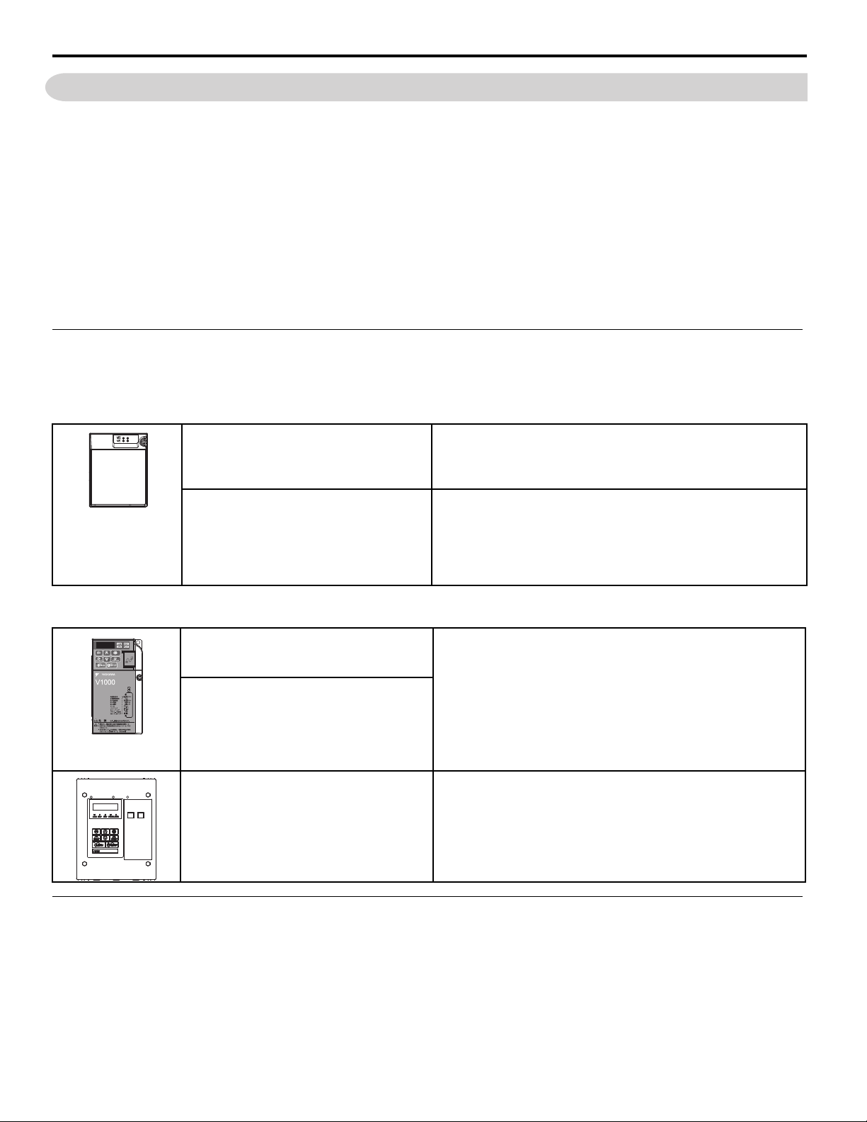
Applicable Documentation
The following manuals are available for the PROFINET option:
PROFINET Option
Yaskawa AC Drive
V1000-Series Option
SI-EP3/V PROFINET Installation Manual
Manual No: TOEP YEACOM 06
Yaskawa AC Drive
V1000-Series Option
SI-EP3/V PROFINET
Technical Manual
Manual No: SIEP YEACOM 06
(This manual)
Read this manual first.
The installation manual is packaged with the option and contains
information required to install the option, verify operation, and set up
related drive parameters.
The technical manual contains detailed information about the option
pertaining to communication protocols, and supported features and
messaging. In the U.S., access; http://www.yaskawa.com to obtain the
Technical Manual. Customers in other areas should contact a Yaskawa
representative.
Yaskawa Drive
Yaskawa AC Drive
V1000 Quick Start Guide
Manual: TOEP C710606 47
Yaskawa AC Drive
V1000 Technical Manual
Manual: SIEP C710606 18
Yaskawa AC Drive
V1000 NEMA Type 4X/IP66 Installation
Manual
Manual: TOBP C710606 35
The drive manuals cover basic installation, wiring, operation
procedures, functions, troubleshooting, and maintenance information.
The manuals also include important information about parameter
settings and drive tuning.
Access these sites to obtain Yaskawa instruction manuals;
U.S.: http://www.yaskawa.com
Europe: http://www.yaskawa.eu.com
Japan: http://www.e-mechatronics.com
Other areas: contact a Yaskawa representative.
This manual contains basic information required to install the V1000
NEMA Type 4X/IP66 drive. Carefully review this manual along with
the Quick Start Guide accompanying the
NEMA Type 4X/IP66.
Terms
Note: Indicates supplemental information that is not related to safety messages
Drive: Yaskawa AC Drive V1000-Series
Option: Yaskawa AC Drive V1000-Series SI-EP3/V PROFINET option
H: Indicates an engineering unit for hexadecimal number format
1012: Indicates a drive feature or function that is only available in drive software version 1012 or greater
YAS KA WA SIEP YEACOM 06A V1000 Option PROFINET SI-EP3/V Technical Manual 5
1 Preface and Safety
DANGER
W ARNING
CAUTION
NOTICE
DANGER
Registered Trademarks
• All trademarks are the property of their respective owners.
Supplemental Safety Information
Read and understand this manual before installing, operating, or servicing this option. The option must be installed
according to this manual and local codes.
The following conventions are used to indicate safety messages in this manual. Failure to heed these messages could
result in serious or possibly even fatal injury or damage to the products or to related equipment and systems.
Indicates a hazardous situation, which, if not avoided, will result in death or serious injury.
Indicates a hazardous situation, which, if not avoided, could result in death or serious injury.
Indicates a hazardous situation, which, if not avoided, could result in minor or moderate injury.
Indicates an equipment damage message.
General Safety
General Precautions
• The diagrams in this section may include options and drives without covers or safety shields to illustrate details. Be sure to reinstall covers or
shields before operating any devices. The option should be used according to the instructions described in this manual.
• Any illustrations, photographs, or examples used in this manual are provided as examples only and may not apply to all products to which this
manual is applicable.
• The products and specifications described in this manual or the content and presentation of the manual may be changed without notice to improve
the product and/or the manual.
• When ordering new copies of the manual, contact a Yaskawa representative or the nearest Yaskawa sales office and provide the manual number
shown on the front cover.
Heed the safety messages in this manual.
Failure to comply will result in death or serious injury.
The operator is responsible for injuries or equipment damage caused from failure to heed the warnings in the manual.
6 YAS KA WA SIEP YEACOM 06A V1000 Option PROFINET SI-EP3/V Technical Manual
1 Preface and Safety
NOTICE
Do not expose the drive or option to halogen group disinfectants.
Failure to comply may cause damage to the electrical components in the option.
Do not pack the drive in wooden materials that have been fumigated or sterilized.
Do not sterilize the entire package after the product is packed.
Do not modify the drive or option circuitry.
Failure to comply could result in damage to the drive or option and will void warranty.
Yaskawa is not responsible for any modification of the product made by the user.
This product must not be modified.
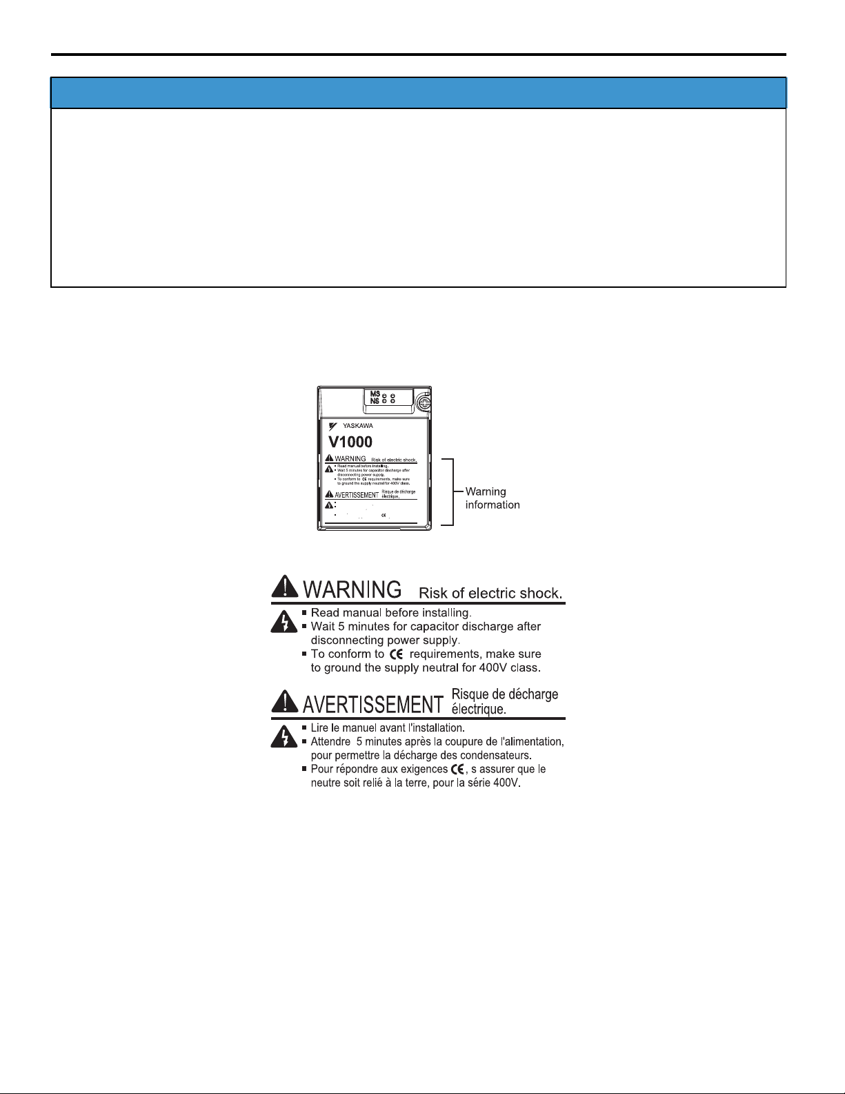
Option Unit Warning Labels
Warning information is displayed on the option unit as shown in the figure below. Follow all warnings and safety
instructions when using the product.
Warning Contents
Lire le manuel avant l'installation.
Attendre 5 minutes apres la coupure de l'alimentation,
pour permettre la decharge des condensateurs.
Pour repondre aux exigences , s assurer que le
neutre soit relie a la terre, pour la serie 400V.
YAS KA WA SIEP YEACOM 06A V1000 Option PROFINET SI-EP3/V Technical Manual 7
2 Product Overview
2 Product Overview
About This Product
The SI-EP3/V option connects the V1000 drive to a PROFINET network and facilitates the exchange of data.
This manual explains the handling, installation and specifications of this product.
The SI-EP3/V option is a simple, networking solution that reduces the cost and time to wire and install factory automation
devices, while providing interchangeability of like components from multiple vendors.
By installing the option to a drive, it is possible to do the following from a PROFINET master device:
• Operate the drive
• Monitor the operation status of the drive
• Change parameter settings.
SI-EP3/V is PROFINET Conformance Class A certified.
Applicable Models
This option can be used with the drive models in Table 1.
Table 1 Applicable Models
Drive Software Version <1>
CIMR-VAAA
CIMR-VABA
CIMR-VAFA
CIMR-VAJA
CIMR-VALA
CIMR-VAGA
CIMR-VAHA
<1> See “PRG” on the drive nameplate for the software version number.
1012
508
8YASKAWA SIEP YEACOM 06A V1000 Option PROFINET SI-EP3/V Technical Manual
3 Receiving
3 Receiving
Please perform the following tasks after receiving the option.
• Inspect the option for damage. Contact the shipper immediately if the option appears damaged upon receipt.
• Verify receipt of the correct model by checking the model number printed on the option nameplate (Refer to Top Views
of Option on page 10 for nameplate positioning).
• Contact your supplier if you have received the wrong model or the option does not function properly.
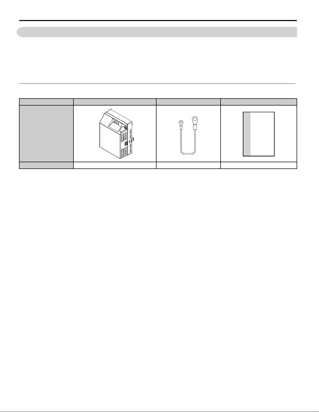
Option Package Contents
Description: Option Unit Ground Wires Installation Manual
MANUAL
_
Quantity: 141
YAS KA WA SIEP YEACOM 06A V1000 Option PROFINET SI-EP3/V Technical Manual 9
4 Option Components
A
B
C
H
E
D
H
G
I
J
R
F
Q
00000000000000
SI-EP3/V
1XXX
P
N
K
M
OL
S
Option with cover removed
CN5 connector port
Option with cover attached
Option Underside
27 mm (1.06 in.)
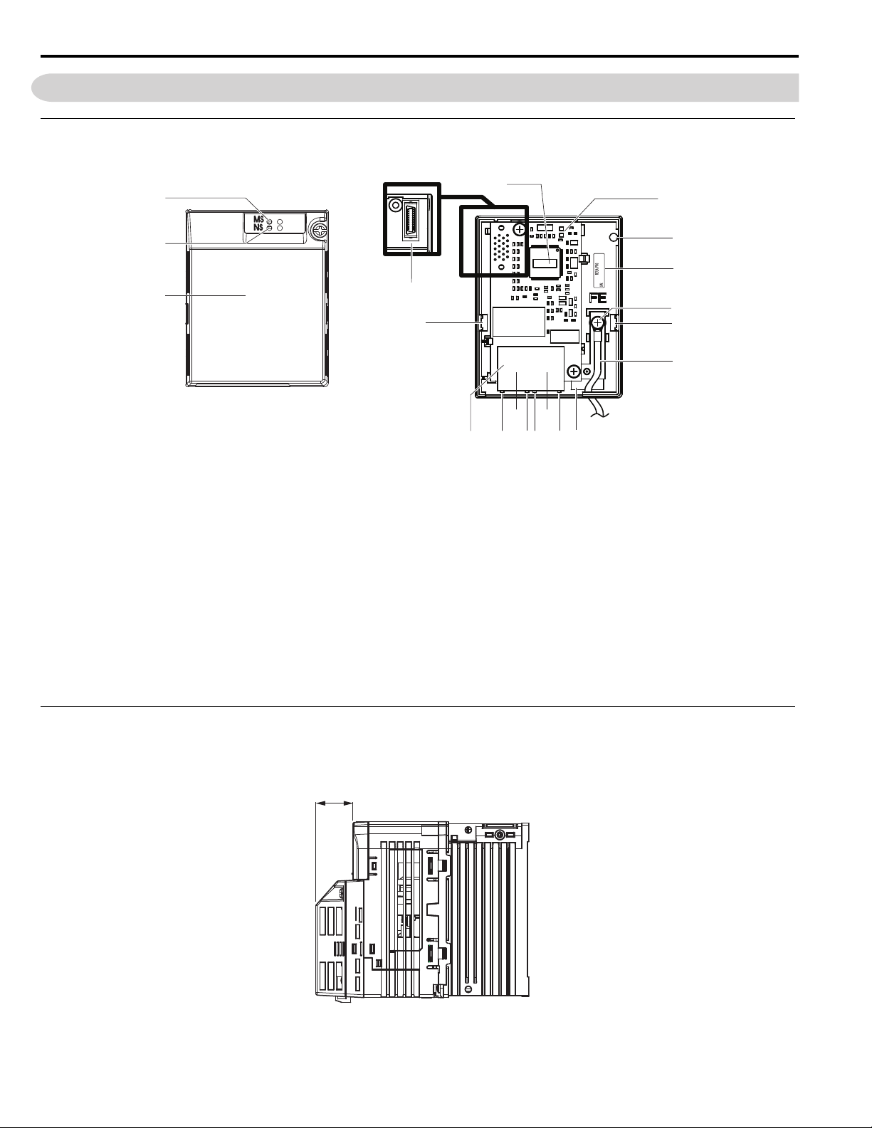
4 Option Components
SI-EP3/V PROFINET Option
Figure 1
A–LED (MS)
<1> K – Port 2 LED (10/100) <1>
B–LED (NS)<1> L–Port 2
C – Option cover M – Port 2 LED (LINK/ACT)
D – PROFINET PCB N – Port 1 LED (10/100)
<1>
<1>
E – Screw hole (attaching option cover) O – Port 1
F – Nameplate P – Port 1 LED (LINK ACT)
<1>
G – Functional Earth cable connection (FE) Q – PROFINET cable connection
H – Mounting tabs R – Option connector (CN5)
I – Ground wire
<2> S – Option Firmware Label (VST)
J – Pass-through hole for ground wire
<1> Refer to Option LED Display on page 11 for details on the LEDs.
<2> One of the four ground wires packaged with the option must be connected during installation.
Figure 1 Top Views of Option
Dimensions with Option Added- IP00/IP20 Open Chassis and IP20/NEMA Type 1
The installed option adds 27 mm (1.06 in.) to the total depth of the drive.
Figure 2
Figure 2 Dimensions
10 YASKAWA SIEP YEACOM 06A V1000 Option PROFINET SI-EP3/V Technical Manual
4 Option Components
RJ45 CAT5e
Network
Communication Cable
RJ45 CAT5e Female
Communication Cable
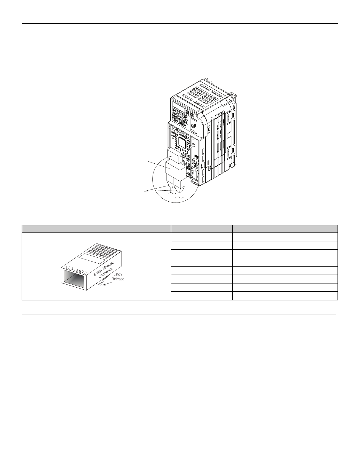
Ports 1 and 2
Terminal CN1
The communication connector on the option is a modular, dual port, RJ45 female communication connector designated
CN1. CN1 is the connection point for a customer supplied male Ethernet network RJ45 CAT5e (STP) communication
cable.
Figure 3
Table 2 Male 8-way Ethernet Modular Connector (Customer-Supplied)
Male EtherNet 8-Way Modular Connector Pin Description
<1> Not used for 10 Mbps and 100 Mbps networks.
Option LED Display
The option has six LEDs:
Bi-color Status LEDs:
• Module status (MS) red/green
• Network status (NS) red/green
Ethernet LEDs (2 each):
Figure 3 RJ45 Connections
1 (Pair 2) Transmit data (TXD) +
2 (Pair 2) Transmit data (TXD) -
3 (Pair 3) Receive data (RXD) +
4 (Pair 1) Not used
5 (Pair 1) Not used <1>
6 (Pair 3) Receive data (RXD) -
7 (Pair 4) Not used
8 (Pair 4) Not used <1>
<1>
<1>
• Network speed-10/100 yellow
• Link status and network activity-Link/Act green
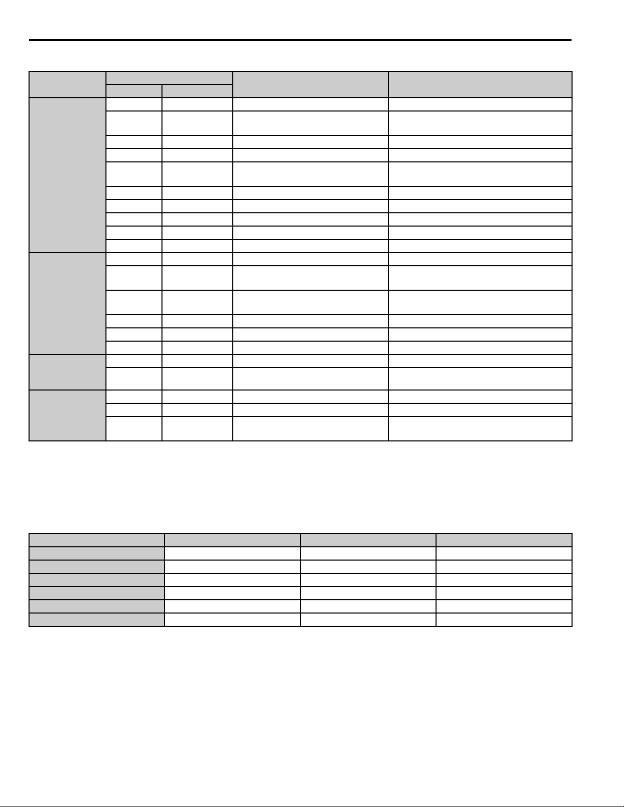
The operational states of the option LEDs after the power-up diagnostic LED sequence is completed are described in
Tabl e 3 . The states with a number in parenthesis are the number of pulses of 250 ms on, 250 ms off cycles, followed by
500 ms off, then repeating the cycle. Wait at least 2 seconds for the power-up diagnostic process to complete before
verifying LED states.
YAS KA WA SIEP YEACOM 06A V1000 Option PROFINET SI-EP3/V Technical Manual 11
4 Option Components
Table 3 Option LED States
Name
MS
(visible through
drive cover)
NS
(visible through
drive cover)
10/100
(visible at
RJ45 cable ports)
LINK/ACT
(visible at
RJ45 cable ports)
Indication
Color Status
– OFF Power supply OFF Power is not being supplied to the drive.
Green ON Option operating
Green Flashing (1) Diagnostics Diagnostic data available.
Green Flashing (2) Configuration tool Identified by a configuration tool.
Red ON Default MAC or fatal error occurred.
Red Flashing (1) Configuration error (non-fatal) Configuration error.
Red Flashing (2) No IP (non-fatal) No IP address assigned.
Red Flashing (3) No station name (non-fatal) No station name assigned.
Red Flashing (4) Init failure (non-fatal) Failed to initialize module.
Green/Red Flashing Option self-test The option is in self-test mode.
– OFF Offline or Power supply OFF –
Green ON Connected
Green Flashing Connected and stopped
Red ON BUS fault Unrecoverable BUS fault.
Red Flashing (1) Lost communication Host communication is temporarily lost.
Red Flashing (2) Lost link No link detected to network.
Yellow OFF 10 Mbps is established –
Yellow ON 100 Mbps is established –
Green OFF Link is not established –
Green ON Link is established –
Green Flashing
Link is established and there is network
activity
Operating Status Remarks
The option is operating normally and
initialization is complete.
Default MAC address has been programmed or
the option has detected an unrecoverable error.
Connection established with I/O controller and
in RUN mode.
Connection established with I/O controller and
in STOP mode.
–
Power-Up Diagnostics
An LED test is performed each time the drive is powered up. The initial boot sequence may take several seconds. After
the LEDs have completed the diagnostic LED sequence, the option is successfully initialized. The LEDs then assume
operational conditions as shown in Tabl e 3 .
Table 4 Power-Up Diagnostic LED Sequence
Sequence Module Status (MS) Network Status (NS) Time (ms)
1 Green OFF 250
2 Red OFF 250
3GreenOFF -
4 Green Green 250
5 Green Red 250
6GreenOFF -
12 YAS KAWA SIEP YEACOM 06A V1000 Option PROFINET SI-EP3/V Technical Manual

5 Installation Preparation
DANGER
W ARNING
NOTICE
5 Installation Preparation
Section Safety
Electrical Shock Hazard
Do not connect or disconnect wiring while the power is on.
Failure to comply will result in death or serious injury.
Disconnect all power to the drive, wait at least five minutes after all indicators are off, measure the DC bus voltage to
confirm safe level, and check for unsafe voltages before servicing. The internal capacitor remains charged after the
power supply is turned off. The charge indicator LED will extinguish when the DC bus voltage is below 50 Vdc.
Electrical Shock Hazard
Do not remove the option cover while the power is on.
Failure to comply could result in death or serious injury.
The diagrams in this section may include options and drives without covers or safety shields to show details. Be sure to
reinstall covers or shields before operating any devices. Use the option according to the instructions described in this
manual.
Do not allow unqualified personnel to use equipment.
Failure to comply could result in death or serious injury.
Maintenance, inspection, and replacement of parts must be performed only by authorized personnel familiar with
installation, adjustment, and maintenance of this product.
Do not touch circuit boards while the power to the drive is on.
Failure to comply could result in death or serious injury.
Do not use damaged wires, stress the wiring, or damage the wire insulation.
Failure to comply could result in death or serious injury.
Fire Hazard
Tighten all terminal screws to the specified tightening torque.
Loose electrical connections could result in death or serious injury by fire due to overheating of electrical connections.
Damage to Equipment
Observe proper electrostatic discharge (ESD) procedures when handling the option, drive, and circuit boards.
Failure to comply may result in ESD damage to circuitry.
Never shut the power off while the drive is running or outputting voltage.
Failure to comply may cause the application to operate incorrectly or damage the drive.
Do not operate damaged equipment.
Failure to comply may cause further damage to the equipment.
Do not connect or operate any equipment with visible damage or missing parts.
YAS KA WA SIEP YEACOM 06A V1000 Option PROFINET SI-EP3/V Technical Manual 13

5 Installation Preparation
NOTICE
Model Number
Location
Do not use unshielded cable for control wiring.
Failure to comply may cause electrical interference resulting in poor system performance.
Use shielded twisted-pair wires and ground the shield to the ground terminal of the drive.
Properly connect all pins and connectors.
Failure to comply may prevent proper operation and possibly damage equipment.
Check wiring to ensure that all connections are correct after installing the option and connecting any other
devices.
Failure to comply may result in damage to the option.
Prior to Installing the Option
Prior to installing the option, wire the drive, make necessary connections to the drive terminals, and verify that the drive
functions normally without the option installed. Refer to the product manual packaged with the drive for information on
wiring and connecting the drive.
Choosing the Correct Installation Procedure
The installation procedure differs between NEMA 4X and IP00/IP20 enclosure types. The enclosure type is identified
within the drive model number. Refer to STEP 1. and Figure 6 on page 15 to identify the drive enclosure type.
1. Locate the drive model number using Figure 4 and Figure 5. Record the model number for use in STEP 2.
Figure 4
Figure 4 Model Number Location: IP00/IP20 Open Chassis and IP20/NEMA Type 1 Enclosure
Figure 5
CIMR-VUBA00012GAA
200V 1PHASE 12 0A/11.0A
S/N J013ZB797110004
Model Number
Location
Figure 5 Model Number Location: NEMA 4X Enclosures
2. Use Figure 6 to find the digit within the model number that identifies the enclosure type. Record the enclosure
type for use in STEP 3.
14 YAS KAWA SIEP YEACOM 06A V1000 Option PROFINET SI-EP3/V Technical Manual
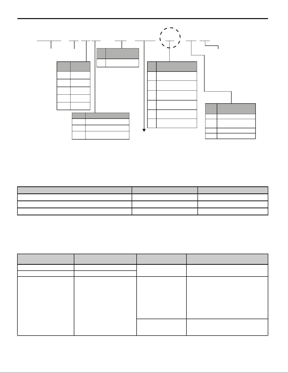
Figure 6
5 Installation Preparation
CIMR - V U 2 A 0001 F A A
Drive
<1> Refer to manual TOBPC71060635 for more information on these models.
<2> Refer to manual TOBPC71060621 for more information on these models.
<3> Drives with these specifications do not guarantee complete protection for the specified environmental condition.
V1000
Series
Region
No.
Code
A Japan
B China
C Europe
T Asia
U USA
No. Voltage Class
B
2
4
Customized
No.
Specifications
A Standard model
1-phase, 200-240 Vac
3-phase, 200-240 Vac
3-phase, 380-480 Vac
Figure 6 Drive Enclosure Type Identification
No.
A
B
F IP20/NEMA Type 1
J
L IP00/Finless <2>
Drive capacity
F
Enclosure Type
IP00/Open-Chassis
IP20/Open-Chassis
NEMA 4X/IP66 <1>G
IP20/Finless <2>
Design
Revision
Order
Environmental
No.
Specification <3>
A
Standard
M
Humidity- and
dust-resistant
N
Oil-resistant
S
Vibration-resistant
3. Use the enclosure type digit recorded from STEP 2. and Table 5 to select the correct installation Procedure A
on page 16 or Procedure B on page 25.
Table 5 Installation Procedure by Enclosure Type
Model Number-Enclosure Type Digit Drive Enclosure Type Installation Procedure
A, B IP20/Open-Chassis Procedure A on page 16
F IP20/NEMA Type 1
<1>
Procedure A on page 16
G NEMA Type 4X/IP66 Procedure B on page 25
<1> Installing the option on an IP20/NEMA Type 1 enclosure drive voids NEMA Type 1 protection while maintaining IP20 conformity.
4. Tool requirements. Select tools for your enclosure type and model, refer to Table 6. Next, go to the chosen
installation Procedure A on page 16 or Procedure B on page 25 from STEP 3.
Note: Tools required to prepare the option cables for wiring are not listed in this manual.
Table 6 Tool Requirements
Model Number
Enclosure Type Digit
A, B IP20/Open-Chassis
F IP20/NEMA Type 1
G NEMA Type 4X/IP66
<1> Screw sizes vary by drive capacity. Select a screwdriver appropriate for the drive capacity.
Drive Enclosure Type Drive Capacity Tool s
All
2A0030G/H
2A0040G/H
2A0056G/H
2A0069G/H
4A0018G/H
4A0023G/H
4A0031G/H
4A0038G/H
Other capacities
Phillips screwdriver M3 metric/#1, #2 U.S. standard size <1>
10 mm socket wrench
Phillips screwdriver M3 metric/#1, #2 U.S. standard size
8 mm socket wrench
Phillips screwdriver M3 metric/#1, #2 U.S. standard size
<1>
<1>
YAS KA WA SIEP YEACOM 06A V1000 Option PROFINET SI-EP3/V Technical Manual 15

6 Procedure A
6 Procedure A
Use Procedure A steps to install the option on drives with IP00/IP20 Open Chassis & IP20/NEMA Type 1 enclosures
or enclosure type digits A, B or F within the model number.
Procedure A Steps
DANGER! Electrical Shock Hazard. Do not connect or disconnect wiring while the power is on. Failure to comply will result in death or
serious injury. Before installing the option, disconnect all power to the drive. The internal capacitor remains charged even after the
power supply is turned off. The charge indicator LED will extinguish when the DC bus voltage is below 50 Vdc. To prevent electric
shock, wait at least five minutes after all indicators are off and measure the DC bus voltage level to confirm safe level.
NOTICE: Damage to Equipment. Observe proper electrostatic discharge procedures (ESD) when handling the option, drive, and circuit
boards. Failure to comply may result in ESD damage to circuitry.
1. Shut off power to the drive, wait at least five minutes after confirming the DC bus voltage is safe, then loosen the
screw that fastens the front cover in place and remove the front cover. This drive front cover will be replaced by
Figure 7
the option cover. Cover removal varies depending on drive size.
Figure 7 Remove the Front Cover
2. The remaining installation steps differ by drive model. Find the drive model number and identify the Enclosure
Type Digit on the drive nameplate and refer to the appropriate Table 7 row and “Proceed to STEP” column.
Table 7 Procedure A- Steps by Drive Model
Enclosure Type Digit within
Model Number
A, B IP20/Open-Chassis CIMR-VAB 3. on page 17
F IP20/NEMA Type 1
<1> Installing the option on an IP20/NEMA Type 1 enclosure drive voids NEMA Type 1 protection while maintaining IP20 conformity.
Enclosure Type Drive Model Proceed to STEP
<1>
CIMR-VAF 7. on page 18
16 YASKAWA SIEP YEACOM 06A V1000 Option PROFINET SI-EP3/V Technical Manual
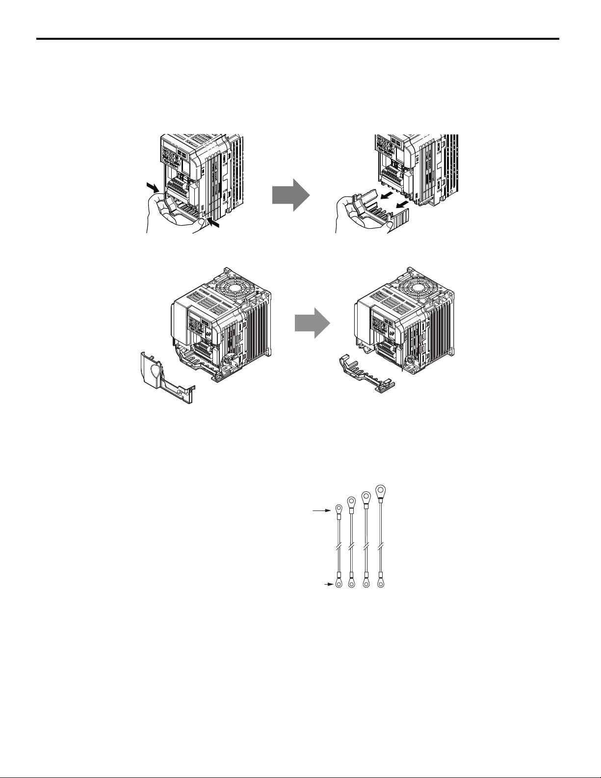
3. IP20/Open-Chassis models CIMR-VAB.
Remove the bottom cover of the drive. Apply pressure using fingers to the tabs on each side of the bottom cover.
Pull the bottom cover away from the drive while pushing in on the tabs to release the cover from the drive. Refer
to Figure 8 for details.
Refer to Figure 9 for drive models CIMR-VBA0006B to BA0018B, 2A0010B to 2A0069B, and 4A0001B to
Figure 8
Figure 9
4A0038B, which require removing the terminal cover prior to removing the bottom cover.
Figure 8 Remove the Bottom Cover on an IP20/Open-Chassis Drive
(Models CIMR-VBA0001B to BA0003B and 2A0001B to 2A0006B)
6 Procedure A
Figure 9 Remove the Terminal Cover and Bottom Cover on an IP20/Open-Chassis Drive
(Models CIMR-VBA0006B to BA0018B; 2A0010B to 2A0069B; 4A0001B to 4A0038B)
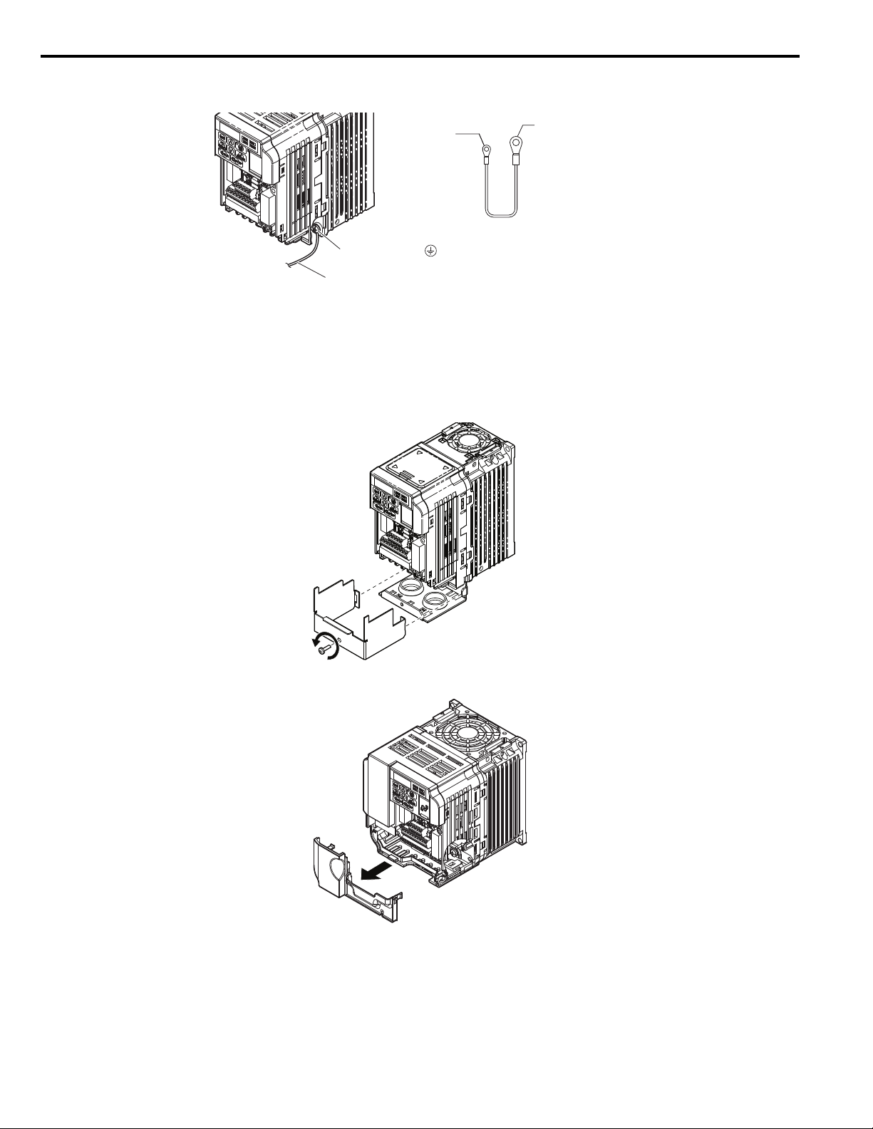
4. Select one of the four different length ground wires packaged with the option.
Choose the proper ground wire by first removing the ground terminal screw from the drive, Figure 11. Test fit the
screw (size M3.5 to M6) into each of the four ground drive-side ring lugs prior to installation. Ground wire
Figure 10
selection varies by drive model.
To drive ground terminal
Screw size: M3.5 to M6
To Option ground screw FE
Screw size: M3
Figure 10 Ground Wire Selection
YAS KA WA SIEP YEACOM 06A V1000 Option PROFINET SI-EP3/V Technical Manual 17
6 Procedure A
5. On IP20/Open-Chassis models, connect the drive side of the ground wire to the drive ground terminal.
Figure11
Drive-side
Ring lug for
Option ground FE
Size: M3
Ground wire
Ground terminal
Ground wire
ground terminal
ring lug (size varies):
M3.5 to M6
Figure 11 Ground Wire Connection on IP20/Open-Chassis
6. Proceed to STEP 12. on page 20 to continue the option installation procedure for IP20/Open-Chassis models.
7. From STEP 2. for IP20/NEMA Type 1 enclosure models CIMR-VAF, loosen the screw on the front of
the NEMA Type 1 terminal cover and remove it from the drive. Refer to Figure 12 for details.
Refer to Figure 13 for drive models CIMR-VBA0006F to BA0018F, 2A0010F to 2A0069F, and 4A0001F to
4A0038F, which require removing the plastic terminal cover prior to removing the NEMA Type 1 terminal cover.
Figure 12
Figure 12 Remove the NEMA Type 1 Terminal Cover
Figure 13
Figure 13 Remove the Terminal Cover on an IP20/NEMA Type 1 Drive
(Models CIMR-VBA0006F to BA0018F; 2A0010F to 2A0069F; 4A0001F to 4A0038F)
18 YAS KAWA SIEP YEACOM 06A V1000 Option PROFINET SI-EP3/V Technical Manual
6 Procedure A
To Option ground screw FE
Screw size: M3
To drive ground terminal
Screw size: M3.5 to M6
Ground terminal
Ground wire
Drive ground terminal/
located on NEMA Type 1
conduit bracket screw
Ground wire
Drive-side
ground terminal
ring lug
(size varies):
M3.5 to M6
Ring lug for
Option ground
FE
Size: M3
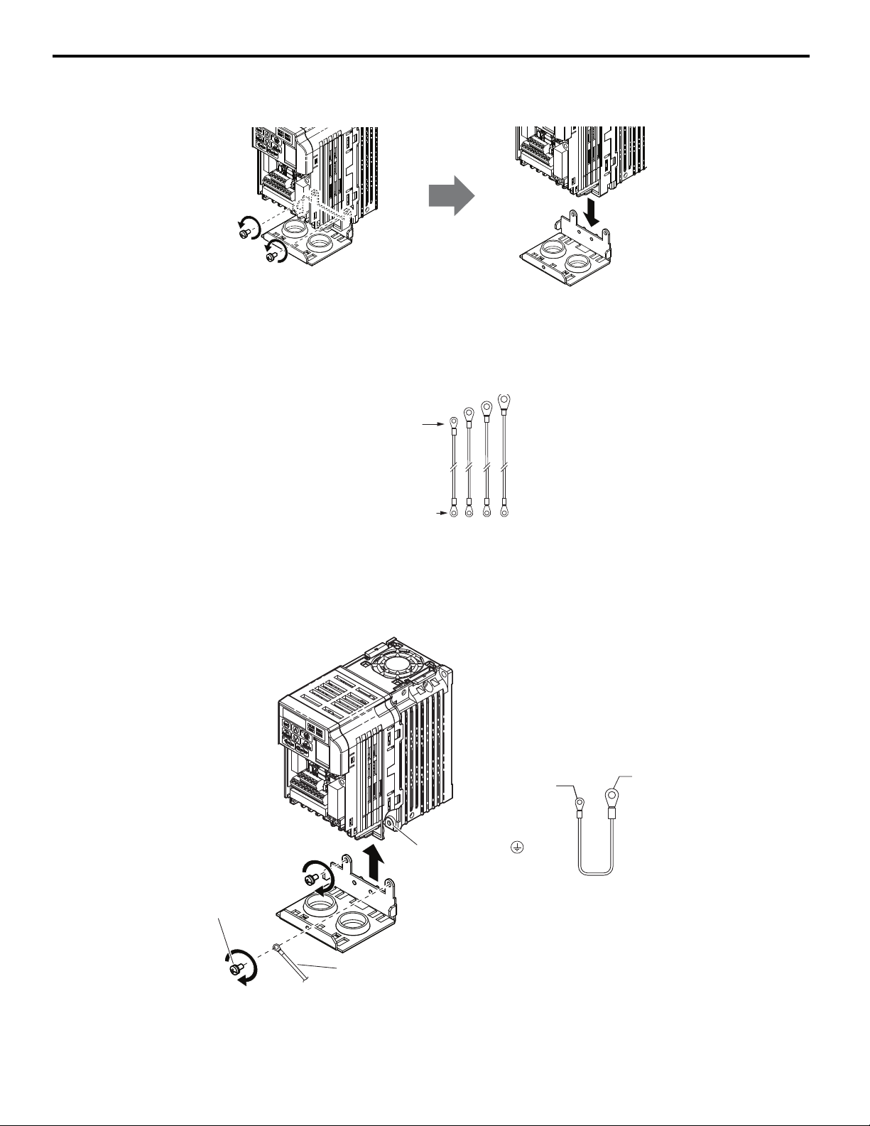
8. Loosen the screws attaching the NEMA Type 1 conduit bracket to the drive to remove the NEMA Type 1 conduit
Figure 14
bracket.
Figure 14 Remove the NEMA Type 1 Conduit Bracket
9. Select one of the four different length ground wires packaged with the option, Figure 15. Choose the proper
ground wire by first removing the ground terminal screw from the drive Figure 16. Test fit the screw (size M3.5 to
M6) into each of the four ground drive-side ring lugs prior to installation. Ground wire selection varies by drive
Figure 15
model.
10. On IP20/NEMA Type 1 enclosure drives, the screw for the drive ground terminal also acts as one of the screws
that attaches the NEMA Type 1 conduit bracket to the drive. Reattach the NEMA Type 1 conduit bracket
according to Figure 16 and connect the drive-side of the ground wire to the drive ground terminal.
Figure 16
Figure 15 Ground Wire Selection
Figure 16 Reattach the NEMA Type 1 Conduit Bracket and Connect the Ground Wire
YAS KA WA SIEP YEACOM 06A V1000 Option PROFINET SI-EP3/V Technical Manual 19
6 Procedure A
IP20/NEMA Type 1 Enclosure
IP20/Open-Type
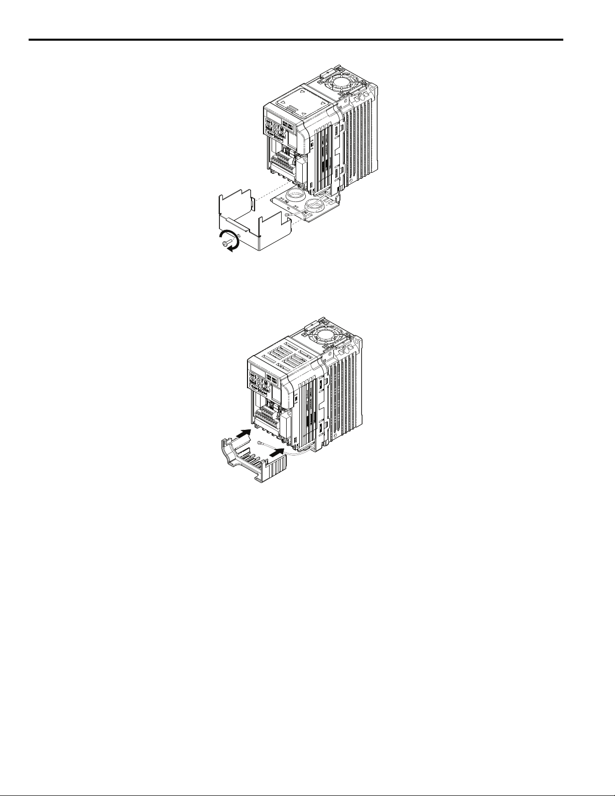
11. Reattach the IP20/NEMA Type 1 bottom terminal cover according to Figure 17. Proceed to STEP 13.
Figure 17
Figure 17 Reattach the Bottom Cover IP20/NEMA Type 1
12. Reattach the IP20/Open Type bottom cover. Keep the ground wire inside of the bottom cover when reattaching.
Figure 18
Figure 18 Reattach the Bottom Cover IP20/Open Type
20 YAS KAWA SIEP YEACOM 06A V1000 Option PROFINET SI-EP3/V Technical Manual
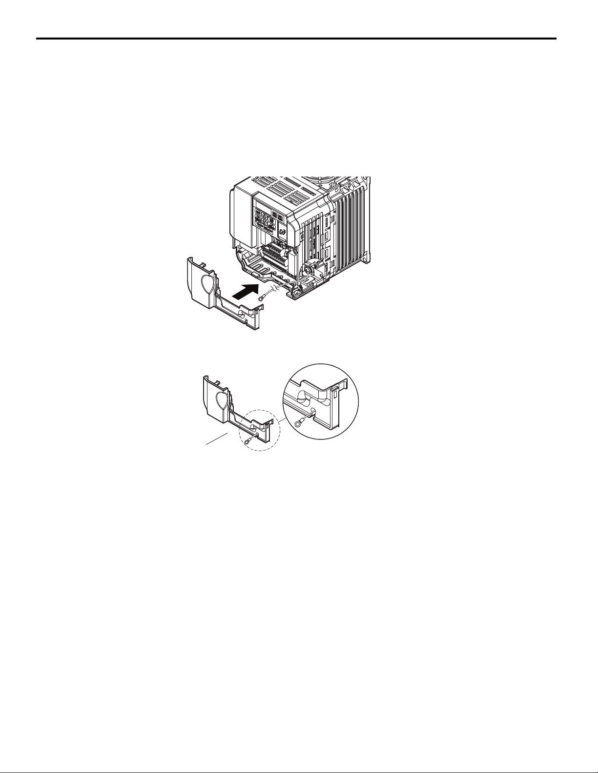
13. Reinstall the terminal cover on these models.
Terminal cover
Ground wire
routing notch
(model specific)
Refer to Figure 19.
CIMR-VBA0006 to BA0018,
V2A0010 to 2A0069, and
V4A0001 to 4A0038.
These models require routing the ground wire through the notch on the bottom of the terminal cover.
Refer to Figure 20.
CIMR-VBA0006 to BA0018,
V2A0010 to 2A0020, and
Figure 19
V4A0001 to 4A0011.
6 Procedure A
Figure 20
(Models CIMR-VBA0006 to BA0018; 2A0010 to 2A0069; 4A0001 to 4A0038)
Figure 19 Reattach the Terminal Cover
Figure 20 Terminal Cover Ground Wire Notch
(Models CIMR-VBA0006 to BA0018; 2A0010 to 2A0020; 4A0001 to 4A0011)
YAS KA WA SIEP YEACOM 06A V1000 Option PROFINET SI-EP3/V Technical Manual 21
6 Procedure A
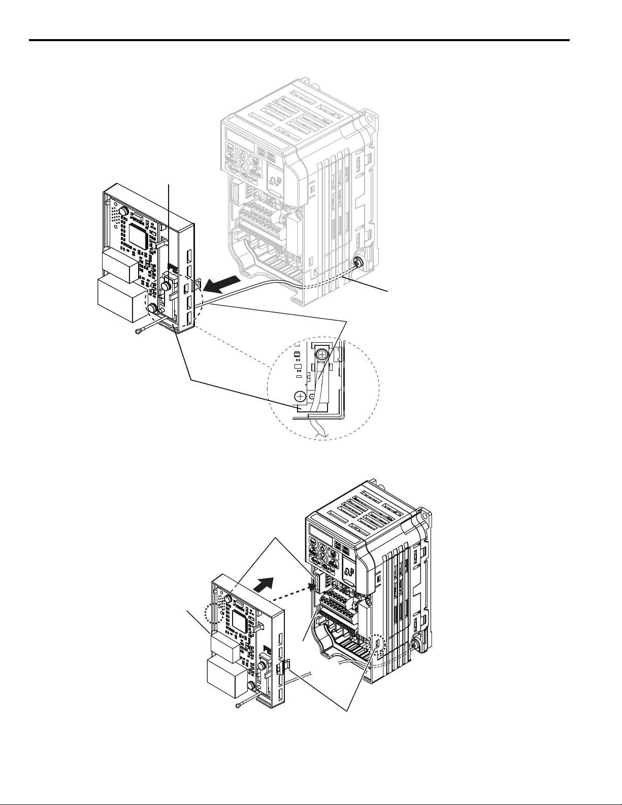
Route ground wire through
inside of drive bottom cover
Option unit ground
terminal (FE)
Ground wire
Option
through-hole for
ground wire
Line up tabs
CN5 Connector
Ta b
Ta b
14. Refer to Figure 21 for ground wire routing.
Figure 21
Figure 21 Ground Wire Routing
15. Attach the option to the drive. Properly seat the tabs on the left and right sides of the option to the drive case.
Figure 22
Figure 22 Connect the Option
22 YAS KAWA SIEP YEACOM 06A V1000 Option PROFINET SI-EP3/V Technical Manual
Loading...