


Owner’s Manual
Keep This Manual For Future Reference.
E

FCC INFORMATION (U.S.A.)
1.IMPORTANT NOTICE: DO NOT MODIFY THIS UNIT! This product, when installed as indicated in the instructions contained in this manual, meets FCC requirements. Modifications not expressly approved by Yamaha may void your authority, granted by the FCC, to use the product.
2.IMPORTANT: When connecting this product to accessories and/or another product use only high quality shielded cables. Cable/s supplied with this product MUST be used. Follow all installation instructions. Failure to follow instructions could void your FCC authorization to use this product in the USA.
3.NOTE: This product has been tested and found to comply with the requirements listed in FCC Regulations, Part 15 for Class “B” digital devices. Compliance with these requirements provides a reasonable level of assurance that your use of this product in a residential environment will not result in harmful interference with other electronic devices. This equipment generates/uses radio frequencies and, if not installed and used according to the instructions found in the users manual, may cause interference harmful to the operation of other electronic devices. Compliance with FCC regulations does not guarantee that interference will not occur in all installations. If this product is found to be the source of interference, which can be determined by turning the unit “OFF” and “ON”, please try to eliminate the problem by using one of the following measures: Relocate either this product or the device that is being affected by the interference. Utilize power outlets that are on different branch (circuit breaker or fuse) circuits or install AC line filter/s. In the case of radio or TV interference, relocate/reorient the antenna. If the antenna lead-in is 300 ohm ribbon lead, change the lead-in to coaxial type cable. If these corrective measures do not produce satisfactory results, please contact the local retailer authorized to distribute this type of product. If you can not locate the appropriate retailer, please contact Yamaha Corporation of America, Electronic Service Division, 6600 Orangethorpe Ave, Buena Park, CA 90620
The above statements apply ONLY to those products distributed by Yamaha Corporation of America or its subsidiaries.
WARNING: THIS APPARATUS MUST BE EARTHED
IMPORTANT
THE WIRES IN THIS MAINS LEAD ARE COLOURED IN ACCORDANCE WITH THE FOLLOWING CODE:
GREEN-AND-YELLOW : EARTH
BLUE : NEUTRAL
BROWN : LIVE
As the colours of the wires in the mains lead of this apparatus may not correspond with the coloured markings identifying the terminals in your plug, proceed as follows:
The wire which is coloured GREEN and YELLOW must be connected to the terminal in the plug which is marked by the letter E or by the safety earth symbol  or coloured GREEN and YELLOW.
The wire which is coloured BLUE must be connected to the terminal which is marked with the letter N or coloured BLACK.
The wire which is coloured BROWN must be connected to the terminal which is marked with the letter L or coloured RED.
*This applies only to products distributed by YAMAHA KEMBLE MUSIC (U.K.) LTD.
ADVARSEL! Lithiumbatteri—Eksplosionsfare ved fejlagtig
håndtering. Udskiftning må kun ske med batteri af samme fabrikat og type. Levér det brugte batteri tilbage til leverandoren.
VARNING
Explosionsfara vid felaktigt batteribyte. Använd samma batterityp eller en ekvivalent typ som rekommenderas av apparattillverkaren. Kassera använt batteri enligt fabrikantens instruktion.
VAROITUS
Paristo voi räjähtää, jos se on virheellisesti asennettu. Vaihda paristo ainoastaan laitevalmistajan suosittelemaan tyyppiin. Hävitä käytetty paristo valmistajan ohjeiden mukaisesti.
NEDERLAND |
THE NETHERLANDS |
● Dit apparaat bevat een lithium batterij voor geheugen |
● This apparatus contains a lithium battery for memory |
back-up. |
back-up. |
● Raadpleeg uw leverancier over de verwijdering van de |
● For the removal of the battery at the moment of the |
batterij op het moment dat u het apparaat ann het einde |
disposal at the end of the service life please consult your |
van de levensduur afdankt of de volgende Yamaha Service |
retailer or Yamaha Service Center as follows: |
Afdeiing: |
Yamaha Music Nederland Service Center |
Yamaha Music Nederland Service Afdeiing |
Address: Kanaalweg 18-G, 3526 KL |
Kanaalweg 18-G, 3526 KL UTRECHT |
UTRECHT |
Tel. 030-2828425 |
Tel: 030-2828425 |
● Gooi de batterij niet weg, maar lever hem in als KCA. |
● Do not throw away the battery. Instead, hand it in as small |
|
chemical waste. |
|
|
This product contains a high intensity lamp that contains a small amount of mercury. Disposal of this material may be regulated due to environmental considerations. For disposal information in the United States, refer to the Electronic Industries Alliance web site: www.eiae.org
* This applies only to products distributed by YAMAHA CORPORATION OF AMERICA. |
(mercury) |

Important Information |
3 |
Important Information
Warnings
•Connect this unit’s power cord only to an AC outlet of the type stated in this Owner’s Manual or as marked on the unit. Failure to do so is a fire and electrical shock hazard.
•Do not allow water to enter this unit or allow the unit to become wet. Fire or electrical shock may result.
•Do not place heavy objects, including this unit, on top of the power cord. A damaged power cord is a fire and electrical shock hazard. In particular, be careful not to place heavy objects on a power cord covered by a carpet.
•Do not place a container with liquid or small metal objects on top of this unit. Liquid or metal objects inside this unit are a fire and electrical shock hazard.
•This unit is equipped with a dedicated ground connection to prevent electrical shock. Before connecting the power plug to an AC outlet, be sure to ground the unit. If the power cord has a three-pin plug, it will provide sufficient grounding so long as the AC outlet is grounded correctly.
•Do not scratch, bend, twist, pull, or heat the power cord. A damaged power cord is a fire and electrical shock hazard.
•Do not remove the unit’s cover. You could receive an electrical shock. If you think internal inspection, maintenance, or repair is necessary, contact your dealer.
•Do not modify the unit. Doing so is a fire and electrical shock hazard.
•If lightning begins to occur, turn off the power switch of the unit as soon as possible, and unplug the power cable plug from the electrical outlet.
•If there is a possibility of lightning, do not touch the power cable plug if it is still connected. Doing so may be an electrical shock hazard.
•Use only the included power cord for this unit. Using other types may be a fire and electrical shock hazard.
•The DM2000 has six rear-panel slots for installing mini-YGDAI cards. For technical reasons, certain card combinations are not supported. Before installing any cards, check the Yamaha web site to if your card is compatible. Installing cards that are not endorsed by Yamaha may cause electrical shock, fire, or damage to the unit.
•If the power cord is damaged (i.e., cut or a bare wire is exposed), ask your dealer for a replacement. Using the unit with a damaged power cord is a fire and electrical shock hazard.
•If you notice any abnormality, such as smoke, odor, or noise, or if a foreign object or liquid gets inside the unit, turn it off immediately. Remove the power cord from the AC outlet. Consult your dealer for repair. Using the unit in this condition is a fire and electrical shock hazard.
•Should this unit be dropped or the cabinet be damaged, turn the power switch off, remove the power plug from the AC outlet, and contact your dealer. If you continue using the unit without heeding this instruction, fire or electrical shock may result.
Cautions
•Keep this unit away from the following locations:
—Locations exposed to oil splashes or steam, such as near cooking stoves, humidifiers, etc.
—Unstable surfaces, such as a wobbly table or slope.
—Locations exposed to excessive heat, such as inside a car with all the windows closed, or places that receive direct sunlight.
—Locations subject to excessive humidity or dust accumulation.
DM2000 Version 2—Owner’s Manual

4 Important Information
•Hold the power cord plug when disconnecting it from an AC outlet. Never pull the cord. A damaged power cord is a potential fire and electrical shock hazard.
•Do not touch the power plug with wet hands. Doing so is a potential electrical shock hazard.
•This unit has ventilation holes along the front underside and at the rear to prevent the internal temperature from rising too high. Do not block them. Blocked ventilation holes are a fire hazard. In particular, do not operate the unit while it’s on its side, is upside down, or while it’s covered with a cloth or dust sheet.
•If you are using the optional MB2000 Peak Meter Bridge, do not hold only the MB2000 when you move the entire unit. Otherwise, the meter angle may be deformed or damaged, the main unit may malfunction, or you may be injured if the unit falls.
•This unit is heavy. Use two or more people to carry it.
•When you transport or move the DM2000 with the MB2000 attached, do not permit impact or stress on the cable connector that connects the MB2000 to the DM2000. Otherwise, malfunction may occur.
•To relocate the unit, turn the power switch off, remove the power plug from the AC outlet, and remove all connecting cables. Damaged cables may cause fire or electrical shock.
•If you know you will not use this unit for a long period of time, such as when going on vacation, remove the power plug from the AC outlet. Leaving it connected is a potential fire hazard.
•The inside of the unit should be cleaned periodically. Dust accumulation inside the unit may cause malfunction and is a potential fire hazard. Consult your dealer for information about cleaning.
•To prevent electrical shock when cleaning the unit, remove the power plug from the AC outlet.
•Do not apply oil, grease, or contact cleaner to the faders. Doing so may cause problems with electrical contact or fader motion.
Operating Notes
•XLR-type connectors are wired as follows: pin 1–ground, pin 2–hot (+), and pin 3–cold (–).
•Insert TRS phone jacks are wired as follows: sleeve–ground, tip–send, and ring–return.
•The performance of components with moving contacts, such switches, rotary controls, faders, and connectors, deteriorates over time. The rate of deterioration depends on the operating environment and is unavoidable. Consult your dealer about replacing defective components.
•Using a mobile telephone near this unit may induce noise. If noise occurs, use the telephone away from the unit.
•If the message “WARNING Low Battery!” appears when you turn on this unit, contact your dealer as soon as possible about replacing the internal data backup battery. The unit will still operate correctly, but data other than the presets will be lost.
•Before replacing the batteries, back up your data to a memory card, or another unit by using MIDI Bulk Dump.
•The digital circuits of this unit may induce a slight noise into nearby radios and TVs. If noise occurs, relocate the affected equipment.
•When connecting D-sub cables, be sure to tighten the screws on both sides of the connector securely. To disconnect the cable, loosen the screws completely, then remove the cable by holding the connector part. Do not remove the plug by pulling the cable while the screws are still attached. Otherwise, the connector may be damaged, leading to malfunction.
•When you change the wordclock settings on any device in your digital audio system, some devices may output noise, so turn down your power amps beforehand, otherwise your speakers may be damaged.
DM2000 Version 2—Owner’s Manual

SmartMedia Handling Precautions |
5 |
SmartMedia Handling Precautions
•The CARD slot is for use with SmartMedia only. Never attempt to insert any other type of storage media.
•Use only SmartMedia of the type specified in this Owner’s Manual.
•Store SmartMedia in a place free from extreme temperatures, humidity, dust, and dirt.
•Always store SmartMedia in its original case.
•Write only on the designated area.
•When handling SmartMedia, be careful not to touch the gold contacts. Fingerprints, smudges, scratches, or dirt can affect performance.
•Fingerprints and dust should be removed by wiping gently using a soft, dry cloth. Do not use benzene, thinner, cleaning detergent, or a chemical cloth.
•If SmartMedia is stored in a cold place (e.g., overnight in a car), and then moved to a warmer environment, or if the temperature rises sharply, condensation may form on the surface, which may affect performance. In this case, the SmartMedia should be allowed to acclimatize for about one hour before use.
•Insert SmartMedia carefully into the CARD slot, with the gold contacts facing upward.
•Do not bend or twist SmartMedia.
•Do not under any circumstances attempt to use SmartMedia that is cracked or warped. Doing so may seriously damage the CARD slot.
•Do not remove SmartMedia while saving or loading data. Doing so may cause data lose.
•Data stored on SmartMedia can be protected against inadvertent overwriting by attaching a write-protect sticker (supplied with SmartMedia).
Interference
The DM2000 uses high-frequency digital circuits that may cause interference on radio and television equipment located nearby. If interference is a problem, relocate the affected equipment. Using a mobile telephone near the unit may induce noise. In this case use the telephone away from the unit.
DM2000 Exclusion of Certain Responsibility
Manufacturer, importer, or dealer shall not be liable for any incidental damages including personal injury or any other damages caused by improper use or operation of the DM2000.
Trademarks
ADAT MultiChannel Optical Digital Interface is a trademark and ADAT and Alesis are registered trademarks of Alesis Corporation. Apogee is a trademark of Apogee Electronics, Inc. Apple, Mac, and Power Macintosh are registered trademarks and Mac OS is a trademark of Apple Corporation, Inc. HUI is a trademark of Mackie Designs, Inc. Intel and Pentium are registered trademarks of Intel Corporation. Nuendo is a registered trademark of Steinberg Media Technologies AG. Pro Tools is a trademark or registered trademark of Digidesign and/or Avid Technology, Inc. SmartMedia is a trademark of Toshiba, Corp. Sony is a registered trademark of Sony Corporation, Inc. Tascam Digital Interface is a trademark and Tascam and Teac are registered trademarks of Teac Corporation. Microsoft and Windows are registered trademarks of Microsoft Corporation, Inc. Waves is a trademark of Waves, Inc. Yamaha is a trademark of Yamaha Corporation. Nuendo and Cubse SX are trademarks of Steinberg Media Technologies GmbH. All other trademarks are the property of their respective holders and are hereby acknowledged.
DM2000 Version 2—Owner’s Manual

6 Important Information
Copyright
No part of the DM2000, its software, or this Owner’s Manual may be reproduced or distributed in any form or by any means without the prior written authorization of Yamaha Corporation.
© 2003 Yamaha Corporation. All rights reserved.
Yamaha Web Site
Further information about the DM2000, related products, and other Yamaha professional audio equipment is available on the Yamaha Professional Audio Web site at: <http://www.yamahaproaudio.com/>.
Package Contents
•DM2000 Digital Production Console
•CD-ROM
•Power cord
•This manual
•Studio Manager Installation Guide
Optional Extras
•MB2000 Peak Meter Bridge
•SP2000 Wooden Side Panels
•LA1800 Light Gooseneck
•mini YGDAI I/O cards
About this Owner’s Manual
This Owner’s Manual covers the DM2000 Digital Production Console.
All the information you need in order to operate the DM2000 Digital Production Console is contained in this manual. Use the table of contents to familiarize yourself with the manual’s organization and to locate tasks and topics, and use the index to locate specific information. Before diving in, it’s recommend that you read the “Operating Basics” chapter, starting on page 51.
Each chapter of this manual discusses a specific section or function of the DM2000. The Input and Output Channels are explained in the following chapters:“Input Channels,”“Bus Outs,”“Aux Sends,”“Matrix Sends,” and “Stereo Out.” Where possible, these chapters have been organized in order of signal flow, from input through to output.
Functions such as EQ and Delay are common to all channels. Rather than repeat the same information over and over, these functions are explained once in the “Common Channel Functions” chapter, which starts on page 127. The “Input Channels,”“Bus Outs,”“Aux Sends,”“Matrix Sends,” and “Stereo Out” chapters contain cross-references to the relevant sections of the “Common Channel Functions” chapter.
Conventions Used in this Manual
The DM2000 features two types of button: physical buttons that you can press (e.g., ENTER and DISPLAY) and buttons that appear on the display pages. References to physical buttons are enclosed in square brackets, for example,“press the [ENTER] button.” References to display page buttons are not emphasized, for example, “press the ENTER button.”
Display pages can be selected by using the [DISPLAY] buttons or the Left Tab Scroll, Right Tab Scroll, and F1–4 buttons below the display. In order to simplify explanations, only the [DISPLAY] button method is mentioned in the procedures. See “Selecting Display Pages” on page 53 for details on all the ways in which pages can be selected.
DM2000 Version 2—Owner’s Manual

Installing the DM2000 |
7 |
Installing the DM2000
The DM2000 should be placed on a strong and stable surface, somewhere that complies with the warnings and cautions listed in the previous sections.
New Functions in DM2000 Version 2
The following functions have been added to the DM2000 as part of the upgrade of the firmware from version 1.2 to version 2.0.
Control Surface
•When you operate the faders (for fader levels) or Encoders (for pan settings), the corresponding fader level or pan setting appears on the channel strip display.
•You can switch the indication on the channel strip display between channel name/ID and port name/ID. → page 276
•Encoder mode now features an assignable function, ALT LAYER, which enables you to control the channel level for all 48 channels without switching between layers. → page 61
•There are now 50 assignable Encoder mode parameters. → page 63
Input Channels
•Surround Pan supports 6.1 Surround. → page 97
•You can change the bus assigned to each surround pan channel. → page 99
•The Fader Group Master function enables you to control the overall level of the Fader group channels simultaneously while maintaining the relative level balance of each channel.
→page 92
•The Mute Group Master function enables you to mute all channels in a Mute group simultaneously. → page 90
•The on/off status of the Follow Pan button is reflected in the pan and Surround Pan settings.
→page 93
Aux Sends
•You can exclude channels from Aux Sends (Mix Minus). → page 117
•You can copy the channel fader positions to Aux Sends. → page 118
•You can set all Send levels to nominal simultaneously. → page 112
•If an Aux Send is set to pre-fader, you can set the Pre point before or after the [ON] button. → page 112
Common Channel Functions
•Input and Output Channel Meter pages indicate the gain reduction being applied by the Gate and Compressor. → page 128
•You can select whether the Input Channel’s Pan setting is used when the Input Channel Solo signal is set to Pre Fader. → page 143
•Raising the channel faders for soloed Channels from –∞ can unsolo the Channels.
→page 143
•The AUX SELECT [AUX 1]–[AUX 12] buttons enable you to solo or unsolo Aux Sends.
→page 143
•The Fader Group Master function enables you to control the overall level of the Fader group channels simultaneously while maintaining the relative level balance of each channel.
→page 147
•The Mute Group Master function enables you to mute all channels in a Mute group simultaneously. → page 149
DM2000 Version 2—Owner’s Manual

8 Important Information
Monitor
•The level of the Surround Monitor can be reset to 85dB SPL. → page 160
•A new parameter has been added to Bass Management on the Surround Monitor Setup page. → page 162
•Surround Monitor is also available when Surround mode is set to Stereo.
•You can simultaneously select BUS and ASSIGN1 or BUS and ASSIGN 2 for surround monitoring.
•You can select from Slot Channel 9 through Channel 16 as Surround Monitor signal sources.
•You can simultaneously select 2TRD, D2, D3, A1, or A2, and STEREO, ASSIGN1, or ASSIGN2 as Control Monitor signal sources.
•You can select the Talkback mic signal as the Studio Monitor source. → page 164
Effects, Plug-ins and GEQ
•You can add optional Add-On Effects to the preset effects. → page 178
•The channel faders enable you to adjust the gain for each band in the graphic EQ. → page 184
Scene Memory
•You can globally apply the Fade Time setting to all scenes. → page 189
•You can globally apply the Recall Safe setting to all scenes. → page 190
•Any channel or parameter settings in the current scene can be copied and pasted into other scenes. → page 191
•You can select more parameters for the Recall Safe function. → page 190
Automix
•You can insert the current mix parameters in a region specified in the Automix data. → page 203
•Touching the faders can punch parameter values in and out if the corresponding OVERWRITE button is set to on. → page 194
•Some parameters related to timecode synchronization have been added. → page 278
Remote Control
•The Joystick or the controls in the SELECTED CHANNEL section enable you to control Pro Tools Surround Pan settings.
•The USER DEFINED KEYS enable you to switch windows in the included Studio Manager application software.
•You can remotely control the Yamaha AD8HR A/D Converter.
Other Functions
•A user-assignable layer enables you to assign Channels to Remote layer targets. → page 269
•You can also select General DAW (for DAW software that supports the Pro Tools protocol) or Cubase SX as the target for a Remote layer. → page 253
•Yamaha’s proprietary Advanced DAW protocol has been added to Nuendo, Cubase SX, and General DAW. This enables you to control these devices using the DM2000’s SELECTED CHANNEL section. (Controllable functions vary depending on the DAW software and version you are using.)
•You can now assign any of 214 functions to the USER DEFINED KEYS. → page 283
•You can assign the selected channels to a Fader or Mute group using the USER DEFINED KEYS. → page 283
•An Operation Lock function prevents unintentional edits and uses a password to restrict access to panel operation. → page 280
DM2000 Version 2—Owner’s Manual

New Functions in DM2000 Version 2 |
9 |
•The Oscillator can output sine wave signals with different frequencies to the L and R channels and odd and even buses. → page 279
•You can set the Auto Direct Out On check box so that if you change a channel’s Direct Out destination, the channel Direct Out will automatically be enabled. → page 276
•You can set the Routing ST Pair Link check box so that the routing from paired Channels to the Stereo Bus is linked. → page 276
COMPLIANCE INFORMATION STATEMENT (DECLARATION OF CONFORMITY PROCEDURE)
Responsible Party : Yamaha Corporation of America
Address : 6600 Orangethorpe Ave., Buena Park, Calif. 90620
Telephone : 714-522-9011
Type of Equipment : Digital Production Console
Model Name : DM2000
This device complies with Part 15 of the FCC Rules.
Operation is subject to the following conditions:
1)this device may not cause harmful interference, and
2)this device must accept any interference received including interference that may cause undesired operation.
See user manual instructions if interference to radio reception is suspected.
* This applies only to products distributed by |
(FCC DoC) |
YAMAHA CORPORATION OF AMERICA. |
|
DM2000 Version 2—Owner’s Manual

10 Contents
Contents
1 Welcome . . . . . . . . . . . . . . . . . . . . . . . . . . . . . . . . . 17
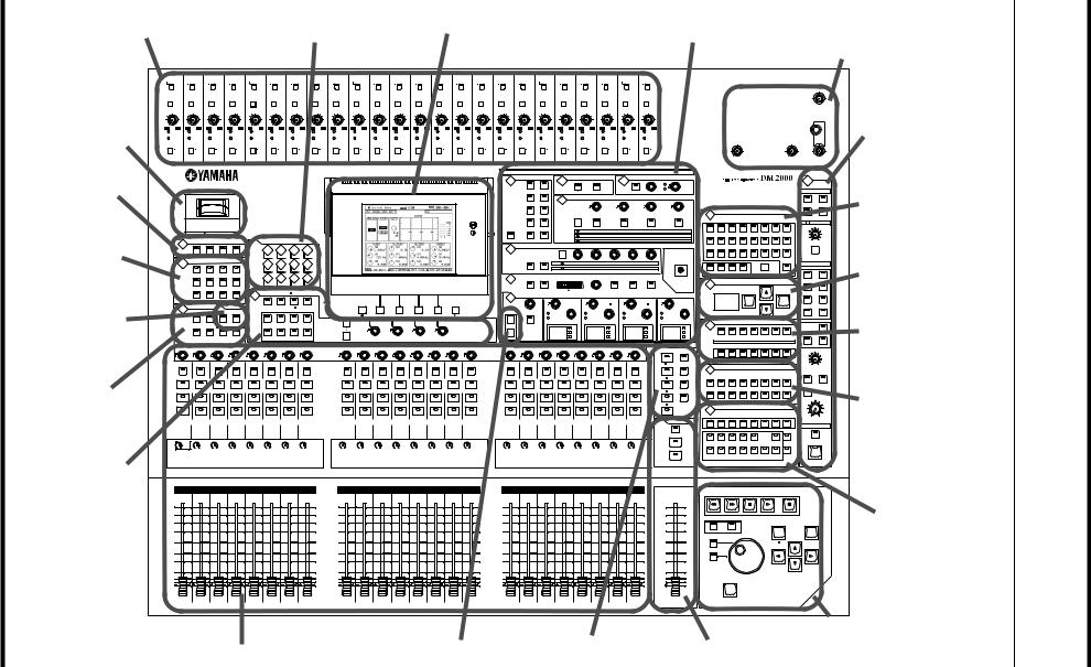
2 Control Surface & Rear Panel . . . . . . . . . . . . . . . . . 20
Control Surface . . . . . . . . . . . . . . . . . . . . . . . . . . . . . . . . . . . . . . . . . . . . . . . . . . . . . 20
Rear Panel . . . . . . . . . . . . . . . . . . . . . . . . . . . . . . . . . . . . . . . . . . . . . . . . . . . . . . . . . 45
3 Operating Basics . . . . . . . . . . . . . . . . . . . . . . . . . . . 51
Connecting the Power Cord . . . . . . . . . . . . . . . . . . . . . . . . . . . . . . . . . . . . . . . . . . 51 Turning On & Off the DM2000 . . . . . . . . . . . . . . . . . . . . . . . . . . . . . . . . . . . . . . . 51 About the Display . . . . . . . . . . . . . . . . . . . . . . . . . . . . . . . . . . . . . . . . . . . . . . . . . . . 52 Selecting Display Pages . . . . . . . . . . . . . . . . . . . . . . . . . . . . . . . . . . . . . . . . . . . . . . . 53 Display History . . . . . . . . . . . . . . . . . . . . . . . . . . . . . . . . . . . . . . . . . . . . . . . . . . . . . 53 Display Page Controls . . . . . . . . . . . . . . . . . . . . . . . . . . . . . . . . . . . . . . . . . . . . . . . 54 Parameter Windows . . . . . . . . . . . . . . . . . . . . . . . . . . . . . . . . . . . . . . . . . . . . . . . . . 54 Confirmation Messages . . . . . . . . . . . . . . . . . . . . . . . . . . . . . . . . . . . . . . . . . . . . . . 54 Title Edit Window . . . . . . . . . . . . . . . . . . . . . . . . . . . . . . . . . . . . . . . . . . . . . . . . . . 54 Using a Keyboard . . . . . . . . . . . . . . . . . . . . . . . . . . . . . . . . . . . . . . . . . . . . . . . . . . . 55 Channel Strip Displays . . . . . . . . . . . . . . . . . . . . . . . . . . . . . . . . . . . . . . . . . . . . . . . 55 Selecting Layers . . . . . . . . . . . . . . . . . . . . . . . . . . . . . . . . . . . . . . . . . . . . . . . . . . . . . 58 Selecting Channels . . . . . . . . . . . . . . . . . . . . . . . . . . . . . . . . . . . . . . . . . . . . . . . . . . 59 Selecting Fader Modes . . . . . . . . . . . . . . . . . . . . . . . . . . . . . . . . . . . . . . . . . . . . . . . 60 Selecting Encoder Modes . . . . . . . . . . . . . . . . . . . . . . . . . . . . . . . . . . . . . . . . . . . . . 61 Assigning Parameters to the ENCODER MODE Assign Buttons . . . . . . . . . . . . 62
4 Analog I/O & the AD Input Section . . . . . . . . . . . . 64
AD Input Section . . . . . . . . . . . . . . . . . . . . . . . . . . . . . . . . . . . . . . . . . . . . . . . . . . . 64
Stereo Out . . . . . . . . . . . . . . . . . . . . . . . . . . . . . . . . . . . . . . . . . . . . . . . . . . . . . . . . . 65
Control Room Monitor Outs . . . . . . . . . . . . . . . . . . . . . . . . . . . . . . . . . . . . . . . . . 65
Studio Monitor Outs . . . . . . . . . . . . . . . . . . . . . . . . . . . . . . . . . . . . . . . . . . . . . . . . 65
Omni Outs . . . . . . . . . . . . . . . . . . . . . . . . . . . . . . . . . . . . . . . . . . . . . . . . . . . . . . . . . 65
2TR Analog INs . . . . . . . . . . . . . . . . . . . . . . . . . . . . . . . . . . . . . . . . . . . . . . . . . . . . . 65
5 Digital I/O & Cascading . . . . . . . . . . . . . . . . . . . . . 66
Wordclocks . . . . . . . . . . . . . . . . . . . . . . . . . . . . . . . . . . . . . . . . . . . . . . . . . . . . . . . . 66
2TR Digital Outs . . . . . . . . . . . . . . . . . . . . . . . . . . . . . . . . . . . . . . . . . . . . . . . . . . . . 68
2TR Digital Ins . . . . . . . . . . . . . . . . . . . . . . . . . . . . . . . . . . . . . . . . . . . . . . . . . . . . . 69
2TR In/Out Sampling Rate Conversion . . . . . . . . . . . . . . . . . . . . . . . . . . . . . . . . . 69
Slot I/O . . . . . . . . . . . . . . . . . . . . . . . . . . . . . . . . . . . . . . . . . . . . . . . . . . . . . . . . . . . . 70
Dithering Digital Outputs . . . . . . . . . . . . . . . . . . . . . . . . . . . . . . . . . . . . . . . . . . . . 73
Monitoring Digital Input Channel Status . . . . . . . . . . . . . . . . . . . . . . . . . . . . . . . 73
Cascading Consoles . . . . . . . . . . . . . . . . . . . . . . . . . . . . . . . . . . . . . . . . . . . . . . . . . 74
6 Input & Output Patching . . . . . . . . . . . . . . . . . . . . 77
Input Patching . . . . . . . . . . . . . . . . . . . . . . . . . . . . . . . . . . . . . . . . . . . . . . . . . . . . . . 77 Output Patching . . . . . . . . . . . . . . . . . . . . . . . . . . . . . . . . . . . . . . . . . . . . . . . . . . . . 79 Naming Input & Output Ports . . . . . . . . . . . . . . . . . . . . . . . . . . . . . . . . . . . . . . . . 82 Patch Select Window . . . . . . . . . . . . . . . . . . . . . . . . . . . . . . . . . . . . . . . . . . . . . . . . 83 Patching with the Encoders . . . . . . . . . . . . . . . . . . . . . . . . . . . . . . . . . . . . . . . . . . . 83
DM2000 Version 2—Owner’s Manual
Contents 11
7 Input Channels . . . . . . . . . . . . . . . . . . . . . . . . . . . |
84 |
Patching Input Channels . . . . . . . . . . . . . . . . . . . . . . . . . . . . . . . . . . . . . . . . . . . . . 84 Metering Input Channels . . . . . . . . . . . . . . . . . . . . . . . . . . . . . . . . . . . . . . . . . . . . . 84 Reversing the Signal Phase . . . . . . . . . . . . . . . . . . . . . . . . . . . . . . . . . . . . . . . . . . . . 84 Gating Input Channels . . . . . . . . . . . . . . . . . . . . . . . . . . . . . . . . . . . . . . . . . . . . . . . 85 Attenuating Input Channels . . . . . . . . . . . . . . . . . . . . . . . . . . . . . . . . . . . . . . . . . . . 87 EQ’ing Input Channels . . . . . . . . . . . . . . . . . . . . . . . . . . . . . . . . . . . . . . . . . . . . . . . 87 Grouping Input Channel EQs . . . . . . . . . . . . . . . . . . . . . . . . . . . . . . . . . . . . . . . . . 87 Input Channel Inserts . . . . . . . . . . . . . . . . . . . . . . . . . . . . . . . . . . . . . . . . . . . . . . . . 87 Compressing Input Channels . . . . . . . . . . . . . . . . . . . . . . . . . . . . . . . . . . . . . . . . . . 87 Grouping Input Channel Compressors . . . . . . . . . . . . . . . . . . . . . . . . . . . . . . . . . . 88 Delaying Input Channels . . . . . . . . . . . . . . . . . . . . . . . . . . . . . . . . . . . . . . . . . . . . . 88 Muting Input Channels (ON/OFF) . . . . . . . . . . . . . . . . . . . . . . . . . . . . . . . . . . . . . 88 Grouping Input Channel Mutes (ON/OFF) . . . . . . . . . . . . . . . . . . . . . . . . . . . . . . 89 Input Channel Mute Master . . . . . . . . . . . . . . . . . . . . . . . . . . . . . . . . . . . . . . . . . . . 90 Setting Input Channel Levels . . . . . . . . . . . . . . . . . . . . . . . . . . . . . . . . . . . . . . . . . . 90 Grouping Input Channel Faders . . . . . . . . . . . . . . . . . . . . . . . . . . . . . . . . . . . . . . . 91 Group Master for Input Channel Faders . . . . . . . . . . . . . . . . . . . . . . . . . . . . . . . . 92 Routing Input Channels . . . . . . . . . . . . . . . . . . . . . . . . . . . . . . . . . . . . . . . . . . . . . . 93 Panning Input Channels . . . . . . . . . . . . . . . . . . . . . . . . . . . . . . . . . . . . . . . . . . . . . . 95 Using Surround Pan . . . . . . . . . . . . . . . . . . . . . . . . . . . . . . . . . . . . . . . . . . . . . . . . . 97 Assigning Surround Channels to Buses . . . . . . . . . . . . . . . . . . . . . . . . . . . . . . . . . . 99 Sending Input Channels to Aux Sends . . . . . . . . . . . . . . . . . . . . . . . . . . . . . . . . . . 102 Soloing Input Channels . . . . . . . . . . . . . . . . . . . . . . . . . . . . . . . . . . . . . . . . . . . . . . 102 Direct Outs . . . . . . . . . . . . . . . . . . . . . . . . . . . . . . . . . . . . . . . . . . . . . . . . . . . . . . . . . 102 Pairing Input Channels . . . . . . . . . . . . . . . . . . . . . . . . . . . . . . . . . . . . . . . . . . . . . . . 102 Viewing Input Channel Settings . . . . . . . . . . . . . . . . . . . . . . . . . . . . . . . . . . . . . . . 102 Copying Input Channel Settings . . . . . . . . . . . . . . . . . . . . . . . . . . . . . . . . . . . . . . . 102 Naming Input Channels . . . . . . . . . . . . . . . . . . . . . . . . . . . . . . . . . . . . . . . . . . . . . . 102 Using the MS Stereo Microphone . . . . . . . . . . . . . . . . . . . . . . . . . . . . . . . . . . . . . . 103
8 Stereo Out . . . . . . . . . . . . . . . . . . . . . . . . . . . . . . . 104
Stereo Out Connectors . . . . . . . . . . . . . . . . . . . . . . . . . . . . . . . . . . . . . . . . . . . . . . . 104 Patching the Stereo Out to Outputs . . . . . . . . . . . . . . . . . . . . . . . . . . . . . . . . . . . . 104 Routing Input Channels to the Stereo Out . . . . . . . . . . . . . . . . . . . . . . . . . . . . . . . 104 Sending Bus Outs to the Stereo Out . . . . . . . . . . . . . . . . . . . . . . . . . . . . . . . . . . . . 104 Metering the Stereo Out . . . . . . . . . . . . . . . . . . . . . . . . . . . . . . . . . . . . . . . . . . . . . . 104 Monitoring the Stereo Out . . . . . . . . . . . . . . . . . . . . . . . . . . . . . . . . . . . . . . . . . . . . 104 Attenuating the Stereo Out . . . . . . . . . . . . . . . . . . . . . . . . . . . . . . . . . . . . . . . . . . . . 104 EQ’ing the Stereo Out . . . . . . . . . . . . . . . . . . . . . . . . . . . . . . . . . . . . . . . . . . . . . . . . 104 Grouping Master EQs . . . . . . . . . . . . . . . . . . . . . . . . . . . . . . . . . . . . . . . . . . . . . . . . 104 Stereo Out Inserts . . . . . . . . . . . . . . . . . . . . . . . . . . . . . . . . . . . . . . . . . . . . . . . . . . . 104 Compressing the Stereo Out . . . . . . . . . . . . . . . . . . . . . . . . . . . . . . . . . . . . . . . . . . 105 Grouping Master Compressors . . . . . . . . . . . . . . . . . . . . . . . . . . . . . . . . . . . . . . . . 105 Muting the Stereo Out (ON/OFF) . . . . . . . . . . . . . . . . . . . . . . . . . . . . . . . . . . . . . . 105 Grouping Master Mutes (ON/OFF) . . . . . . . . . . . . . . . . . . . . . . . . . . . . . . . . . . . . 105 Setting the Stereo Out Level . . . . . . . . . . . . . . . . . . . . . . . . . . . . . . . . . . . . . . . . . . . 105 Grouping Master Faders . . . . . . . . . . . . . . . . . . . . . . . . . . . . . . . . . . . . . . . . . . . . . . 105 Sending the Stereo Out to the Matrix Sends . . . . . . . . . . . . . . . . . . . . . . . . . . . . . . 105 Balancing the Stereo Out . . . . . . . . . . . . . . . . . . . . . . . . . . . . . . . . . . . . . . . . . . . . . 106 Delaying the Stereo Out . . . . . . . . . . . . . . . . . . . . . . . . . . . . . . . . . . . . . . . . . . . . . . 106 Inserting GEQs . . . . . . . . . . . . . . . . . . . . . . . . . . . . . . . . . . . . . . . . . . . . . . . . . . . . . 106 Viewing Stereo Out Settings . . . . . . . . . . . . . . . . . . . . . . . . . . . . . . . . . . . . . . . . . . . 106 Copying Stereo Out Settings . . . . . . . . . . . . . . . . . . . . . . . . . . . . . . . . . . . . . . . . . . 106 Naming the Stereo Out . . . . . . . . . . . . . . . . . . . . . . . . . . . . . . . . . . . . . . . . . . . . . . . 106
DM2000 Version 2—Owner’s Manual

12 Contents
9 Bus Outs . . . . . . . . . . . . . . . . . . . . . . . . . . . . . . . . |
107 |
Patching Bus Outs to Outputs . . . . . . . . . . . . . . . . . . . . . . . . . . . . . . . . . . . . . . . . . |
107 |
Routing Input Channels to Bus Outs . . . . . . . . . . . . . . . . . . . . . . . . . . . . . . . . . . . |
107 |
Metering Bus Outs . . . . . . . . . . . . . . . . . . . . . . . . . . . . . . . . . . . . . . . . . . . . . . . . . . |
107 |
Monitoring Bus Outs . . . . . . . . . . . . . . . . . . . . . . . . . . . . . . . . . . . . . . . . . . . . . . . . |
107 |
Attenuating Bus Outs . . . . . . . . . . . . . . . . . . . . . . . . . . . . . . . . . . . . . . . . . . . . . . . . |
107 |
EQ’ing Bus Outs . . . . . . . . . . . . . . . . . . . . . . . . . . . . . . . . . . . . . . . . . . . . . . . . . . . . |
107 |
Grouping Master EQs . . . . . . . . . . . . . . . . . . . . . . . . . . . . . . . . . . . . . . . . . . . . . . . . |
107 |
Bus Out Inserts . . . . . . . . . . . . . . . . . . . . . . . . . . . . . . . . . . . . . . . . . . . . . . . . . . . . . |
107 |
Compressing Bus Outs . . . . . . . . . . . . . . . . . . . . . . . . . . . . . . . . . . . . . . . . . . . . . . . |
107 |
Grouping Master Compressors . . . . . . . . . . . . . . . . . . . . . . . . . . . . . . . . . . . . . . . . |
107 |
Muting Bus Outs (ON/OFF) . . . . . . . . . . . . . . . . . . . . . . . . . . . . . . . . . . . . . . . . . . |
108 |
Grouping Master Mutes (ON/OFF) . . . . . . . . . . . . . . . . . . . . . . . . . . . . . . . . . . . . |
108 |
Setting Bus Out Levels . . . . . . . . . . . . . . . . . . . . . . . . . . . . . . . . . . . . . . . . . . . . . . . |
108 |
Grouping Master Faders . . . . . . . . . . . . . . . . . . . . . . . . . . . . . . . . . . . . . . . . . . . . . |
108 |
Sending Bus Outs to Matrix Sends . . . . . . . . . . . . . . . . . . . . . . . . . . . . . . . . . . . . . |
108 |
Delaying Bus Outs . . . . . . . . . . . . . . . . . . . . . . . . . . . . . . . . . . . . . . . . . . . . . . . . . . |
108 |
Inserting GEQs . . . . . . . . . . . . . . . . . . . . . . . . . . . . . . . . . . . . . . . . . . . . . . . . . . . . . |
108 |
Soloing Bus Outs . . . . . . . . . . . . . . . . . . . . . . . . . . . . . . . . . . . . . . . . . . . . . . . . . . . . |
108 |
Pairing Bus Outs . . . . . . . . . . . . . . . . . . . . . . . . . . . . . . . . . . . . . . . . . . . . . . . . . . . . |
108 |
Sending Bus Outs to the Stereo Out . . . . . . . . . . . . . . . . . . . . . . . . . . . . . . . . . . . . |
109 |
Viewing Bus Out Settings . . . . . . . . . . . . . . . . . . . . . . . . . . . . . . . . . . . . . . . . . . . . . |
109 |
Copying Bus Out Settings . . . . . . . . . . . . . . . . . . . . . . . . . . . . . . . . . . . . . . . . . . . . |
109 |
Naming Bus Outs . . . . . . . . . . . . . . . . . . . . . . . . . . . . . . . . . . . . . . . . . . . . . . . . . . . |
109 |
10 Aux Sends . . . . . . . . . . . . . . . . . . . . . . . . . . . . . . . |
110 |
Patching Aux Send Masters to Outputs . . . . . . . . . . . . . . . . . . . . . . . . . . . . . . . . . |
110 |
Setting the Aux Send Mode . . . . . . . . . . . . . . . . . . . . . . . . . . . . . . . . . . . . . . . . . . . |
110 |
Pre-Fader or Post-Fader Aux Sends . . . . . . . . . . . . . . . . . . . . . . . . . . . . . . . . . . . . |
111 |
Setting Aux Send Levels . . . . . . . . . . . . . . . . . . . . . . . . . . . . . . . . . . . . . . . . . . . . . . |
111 |
Muting Aux Sends (ON/OFF) . . . . . . . . . . . . . . . . . . . . . . . . . . . . . . . . . . . . . . . . . |
112 |
Aux Send Pages . . . . . . . . . . . . . . . . . . . . . . . . . . . . . . . . . . . . . . . . . . . . . . . . . . . . . |
112 |
Viewing Aux Send Settings . . . . . . . . . . . . . . . . . . . . . . . . . . . . . . . . . . . . . . . . . . . |
114 |
Panning Aux Sends . . . . . . . . . . . . . . . . . . . . . . . . . . . . . . . . . . . . . . . . . . . . . . . . . . |
116 |
Excluding Certain Channels from Aux Sends (Mix Minus) . . . . . . . . . . . . . . . . . |
117 |
Copying Channel Fader Positions to Aux Sends . . . . . . . . . . . . . . . . . . . . . . . . . . |
118 |
Metering Aux Send Masters . . . . . . . . . . . . . . . . . . . . . . . . . . . . . . . . . . . . . . . . . . . |
118 |
Monitoring Aux Send Masters . . . . . . . . . . . . . . . . . . . . . . . . . . . . . . . . . . . . . . . . . |
118 |
Attenuating Aux Send Masters . . . . . . . . . . . . . . . . . . . . . . . . . . . . . . . . . . . . . . . . |
118 |
EQ’ing Aux Send Masters . . . . . . . . . . . . . . . . . . . . . . . . . . . . . . . . . . . . . . . . . . . . |
118 |
Grouping Master EQs . . . . . . . . . . . . . . . . . . . . . . . . . . . . . . . . . . . . . . . . . . . . . . . . |
118 |
Aux Send Master Inserts . . . . . . . . . . . . . . . . . . . . . . . . . . . . . . . . . . . . . . . . . . . . . . |
119 |
Compressing Aux Send Masters . . . . . . . . . . . . . . . . . . . . . . . . . . . . . . . . . . . . . . . |
119 |
Grouping Master Compressors . . . . . . . . . . . . . . . . . . . . . . . . . . . . . . . . . . . . . . . . |
119 |
Muting Aux Send Masters (ON/OFF) . . . . . . . . . . . . . . . . . . . . . . . . . . . . . . . . . . |
119 |
Grouping Master Mutes (ON/OFF) . . . . . . . . . . . . . . . . . . . . . . . . . . . . . . . . . . . . |
119 |
Settings Aux Send Master Levels . . . . . . . . . . . . . . . . . . . . . . . . . . . . . . . . . . . . . . . |
119 |
Grouping Master Faders . . . . . . . . . . . . . . . . . . . . . . . . . . . . . . . . . . . . . . . . . . . . . |
119 |
Sending Aux Sends to Matrix Sends . . . . . . . . . . . . . . . . . . . . . . . . . . . . . . . . . . . . |
119 |
Delaying Aux Send Masters . . . . . . . . . . . . . . . . . . . . . . . . . . . . . . . . . . . . . . . . . . . |
119 |
Inserting GEQs . . . . . . . . . . . . . . . . . . . . . . . . . . . . . . . . . . . . . . . . . . . . . . . . . . . . . |
120 |
Soloing Aux Sends . . . . . . . . . . . . . . . . . . . . . . . . . . . . . . . . . . . . . . . . . . . . . . . . . . |
120 |
Pairing Aux Sends . . . . . . . . . . . . . . . . . . . . . . . . . . . . . . . . . . . . . . . . . . . . . . . . . . . |
120 |
Viewing Aux Send Master Settings . . . . . . . . . . . . . . . . . . . . . . . . . . . . . . . . . . . . . |
120 |
Copying Aux Send Master Settings . . . . . . . . . . . . . . . . . . . . . . . . . . . . . . . . . . . . . |
120 |
Naming Aux Send Masters . . . . . . . . . . . . . . . . . . . . . . . . . . . . . . . . . . . . . . . . . . . . |
120 |
DM2000 Version 2—Owner’s Manual

Contents |
13 |
11 Matrix Sends . . . . . . . . . . . . . . . . . . . . . . . . . . . . . |
121 |
Patching Matrix Send Masters to Outputs . . . . . . . . . . . . . . . . . . . . . . . . . . . . . . . 121 Pre-Fader or Post-Fader Matrix Sends . . . . . . . . . . . . . . . . . . . . . . . . . . . . . . . . . . 121 Setting Matrix Send Levels . . . . . . . . . . . . . . . . . . . . . . . . . . . . . . . . . . . . . . . . . . . . 121 Muting Matrix Sends (ON/OFF) . . . . . . . . . . . . . . . . . . . . . . . . . . . . . . . . . . . . . . . 122 Matrix Send Pages . . . . . . . . . . . . . . . . . . . . . . . . . . . . . . . . . . . . . . . . . . . . . . . . . . . 122 Panning Matrix Sends . . . . . . . . . . . . . . . . . . . . . . . . . . . . . . . . . . . . . . . . . . . . . . . . 123 Viewing Matrix Send Settings . . . . . . . . . . . . . . . . . . . . . . . . . . . . . . . . . . . . . . . . . 124 Metering Matrix Send Masters . . . . . . . . . . . . . . . . . . . . . . . . . . . . . . . . . . . . . . . . . 124 Monitoring Matrix Send Masters . . . . . . . . . . . . . . . . . . . . . . . . . . . . . . . . . . . . . . 124 Attenuating Matrix Send Masters . . . . . . . . . . . . . . . . . . . . . . . . . . . . . . . . . . . . . . 125 EQ’ing Matrix Send Masters . . . . . . . . . . . . . . . . . . . . . . . . . . . . . . . . . . . . . . . . . . 125 Grouping Master EQs . . . . . . . . . . . . . . . . . . . . . . . . . . . . . . . . . . . . . . . . . . . . . . . . 125 Matrix Send Master Inserts . . . . . . . . . . . . . . . . . . . . . . . . . . . . . . . . . . . . . . . . . . . 125 Compressing Matrix Send Masters . . . . . . . . . . . . . . . . . . . . . . . . . . . . . . . . . . . . . 125 Grouping Master Compressors . . . . . . . . . . . . . . . . . . . . . . . . . . . . . . . . . . . . . . . . 125 Muting Matrix Send Masters (ON/OFF) . . . . . . . . . . . . . . . . . . . . . . . . . . . . . . . . 125 Grouping Master Mutes (ON/OFF) . . . . . . . . . . . . . . . . . . . . . . . . . . . . . . . . . . . . 125 Setting Matrix Send Master Levels . . . . . . . . . . . . . . . . . . . . . . . . . . . . . . . . . . . . . . 125 Grouping Master Faders . . . . . . . . . . . . . . . . . . . . . . . . . . . . . . . . . . . . . . . . . . . . . . 126 Balancing Matrix Send Masters . . . . . . . . . . . . . . . . . . . . . . . . . . . . . . . . . . . . . . . . 126 Delaying Matrix Send Masters . . . . . . . . . . . . . . . . . . . . . . . . . . . . . . . . . . . . . . . . . 126 Soloing Matrix Sends . . . . . . . . . . . . . . . . . . . . . . . . . . . . . . . . . . . . . . . . . . . . . . . . 126 Inserting GEQs . . . . . . . . . . . . . . . . . . . . . . . . . . . . . . . . . . . . . . . . . . . . . . . . . . . . . 126 Viewing Matrix Send Master Settings . . . . . . . . . . . . . . . . . . . . . . . . . . . . . . . . . . . 126 Copying Matrix Send Master Settings . . . . . . . . . . . . . . . . . . . . . . . . . . . . . . . . . . . 126 Naming Matrix Send Masters . . . . . . . . . . . . . . . . . . . . . . . . . . . . . . . . . . . . . . . . . 126
12 Common Channel Functions . . . . . . . . . . . . . . . . . 127
Metering . . . . . . . . . . . . . . . . . . . . . . . . . . . . . . . . . . . . . . . . . . . . . . . . . . . . . . . . . . . 127 Attenuating Signals . . . . . . . . . . . . . . . . . . . . . . . . . . . . . . . . . . . . . . . . . . . . . . . . . . 130 Using EQ . . . . . . . . . . . . . . . . . . . . . . . . . . . . . . . . . . . . . . . . . . . . . . . . . . . . . . . . . . 131 Grouping Output Channel EQs . . . . . . . . . . . . . . . . . . . . . . . . . . . . . . . . . . . . . . . . 135 Using Inserts . . . . . . . . . . . . . . . . . . . . . . . . . . . . . . . . . . . . . . . . . . . . . . . . . . . . . . . 135 Compressing Channels . . . . . . . . . . . . . . . . . . . . . . . . . . . . . . . . . . . . . . . . . . . . . . . 137 Grouping Output Channel Compressors . . . . . . . . . . . . . . . . . . . . . . . . . . . . . . . . 140 Delaying Channel Signals . . . . . . . . . . . . . . . . . . . . . . . . . . . . . . . . . . . . . . . . . . . . . 141 Soloing Channels . . . . . . . . . . . . . . . . . . . . . . . . . . . . . . . . . . . . . . . . . . . . . . . . . . . . 142 Pairing Channels . . . . . . . . . . . . . . . . . . . . . . . . . . . . . . . . . . . . . . . . . . . . . . . . . . . . 144 Grouping Output Channel Faders . . . . . . . . . . . . . . . . . . . . . . . . . . . . . . . . . . . . . . 146 Group Master for the Output Channel Faders . . . . . . . . . . . . . . . . . . . . . . . . . . . . 147 Grouping Output Channel Mutes (ON/OFF) . . . . . . . . . . . . . . . . . . . . . . . . . . . . 149 Output Channel Mute Master . . . . . . . . . . . . . . . . . . . . . . . . . . . . . . . . . . . . . . . . . 149 Viewing Channel Parameter Settings . . . . . . . . . . . . . . . . . . . . . . . . . . . . . . . . . . . 150 Viewing Channel Fader Settings . . . . . . . . . . . . . . . . . . . . . . . . . . . . . . . . . . . . . . . 151 Copying Channel Settings . . . . . . . . . . . . . . . . . . . . . . . . . . . . . . . . . . . . . . . . . . . . 155 Naming Channels . . . . . . . . . . . . . . . . . . . . . . . . . . . . . . . . . . . . . . . . . . . . . . . . . . . 156
13 Monitoring & Talkback . . . . . . . . . . . . . . . . . . . . . 158
Control Room Monitoring . . . . . . . . . . . . . . . . . . . . . . . . . . . . . . . . . . . . . . . . . . . . 158
Studio Monitoring . . . . . . . . . . . . . . . . . . . . . . . . . . . . . . . . . . . . . . . . . . . . . . . . . . . 159
Surround Monitoring . . . . . . . . . . . . . . . . . . . . . . . . . . . . . . . . . . . . . . . . . . . . . . . . 160
Using Talkback & Slate . . . . . . . . . . . . . . . . . . . . . . . . . . . . . . . . . . . . . . . . . . . . . . . 163
DM2000 Version 2—Owner’s Manual

14 Contents
14 Libraries . . . . . . . . . . . . . . . . . . . . . . . . . . . . . . . . |
165 |
About the Libraries . . . . . . . . . . . . . . . . . . . . . . . . . . . . . . . . . . . . . . . . . . . . . . . . . . 165 General Library Operation . . . . . . . . . . . . . . . . . . . . . . . . . . . . . . . . . . . . . . . . . . . . 165 Channel Library . . . . . . . . . . . . . . . . . . . . . . . . . . . . . . . . . . . . . . . . . . . . . . . . . . . . 166 Input Patch Library . . . . . . . . . . . . . . . . . . . . . . . . . . . . . . . . . . . . . . . . . . . . . . . . . . 167 Output Patch Library . . . . . . . . . . . . . . . . . . . . . . . . . . . . . . . . . . . . . . . . . . . . . . . . 167 GEQ Library . . . . . . . . . . . . . . . . . . . . . . . . . . . . . . . . . . . . . . . . . . . . . . . . . . . . . . . 168 Effects Library . . . . . . . . . . . . . . . . . . . . . . . . . . . . . . . . . . . . . . . . . . . . . . . . . . . . . . 168 Bus to Stereo Library . . . . . . . . . . . . . . . . . . . . . . . . . . . . . . . . . . . . . . . . . . . . . . . . 169 Gate Library . . . . . . . . . . . . . . . . . . . . . . . . . . . . . . . . . . . . . . . . . . . . . . . . . . . . . . . . 170 Comp Library . . . . . . . . . . . . . . . . . . . . . . . . . . . . . . . . . . . . . . . . . . . . . . . . . . . . . . 171 EQ Library . . . . . . . . . . . . . . . . . . . . . . . . . . . . . . . . . . . . . . . . . . . . . . . . . . . . . . . . . 172 Automix Library . . . . . . . . . . . . . . . . . . . . . . . . . . . . . . . . . . . . . . . . . . . . . . . . . . . . 173 Surround Monitor Library . . . . . . . . . . . . . . . . . . . . . . . . . . . . . . . . . . . . . . . . . . . . 173
15 Internal Effects, Plug-Ins & GEQs . . . . . . . . . . . . . 174
About the Effects . . . . . . . . . . . . . . . . . . . . . . . . . . . . . . . . . . . . . . . . . . . . . . . . . . . . 174
Patching Effects Processors . . . . . . . . . . . . . . . . . . . . . . . . . . . . . . . . . . . . . . . . . . . 174
Preset Effects & Types . . . . . . . . . . . . . . . . . . . . . . . . . . . . . . . . . . . . . . . . . . . . . . . . 174
Editing Effects . . . . . . . . . . . . . . . . . . . . . . . . . . . . . . . . . . . . . . . . . . . . . . . . . . . . . . 177
Adding Optional Add-On Effects . . . . . . . . . . . . . . . . . . . . . . . . . . . . . . . . . . . . . . 178
About Plug-Ins . . . . . . . . . . . . . . . . . . . . . . . . . . . . . . . . . . . . . . . . . . . . . . . . . . . . . 179
Configuring Plug-Ins . . . . . . . . . . . . . . . . . . . . . . . . . . . . . . . . . . . . . . . . . . . . . . . . 180
Editing Plug-Ins . . . . . . . . . . . . . . . . . . . . . . . . . . . . . . . . . . . . . . . . . . . . . . . . . . . . 181
About the GEQs . . . . . . . . . . . . . . . . . . . . . . . . . . . . . . . . . . . . . . . . . . . . . . . . . . . . 183
Editing GEQs . . . . . . . . . . . . . . . . . . . . . . . . . . . . . . . . . . . . . . . . . . . . . . . . . . . . . . . 183
Editing the Graphic EQ Using the Channel Faders . . . . . . . . . . . . . . . . . . . . . . . . 184
16 Scene Memories . . . . . . . . . . . . . . . . . . . . . . . . . . |
185 |
About Scene Memories . . . . . . . . . . . . . . . . . . . . . . . . . . . . . . . . . . . . . . . . . . . . . . |
185 |
Auto Scene Memory Update . . . . . . . . . . . . . . . . . . . . . . . . . . . . . . . . . . . . . . . . . . |
186 |
Storing & Recalling Scenes with the SCENE MEMORY Buttons . . . . . . . . . . . . . |
187 |
Using the Scene Memory Page . . . . . . . . . . . . . . . . . . . . . . . . . . . . . . . . . . . . . . . . |
188 |
Fading Scenes . . . . . . . . . . . . . . . . . . . . . . . . . . . . . . . . . . . . . . . . . . . . . . . . . . . . . . |
189 |
Recalling Scenes Safely . . . . . . . . . . . . . . . . . . . . . . . . . . . . . . . . . . . . . . . . . . . . . . . |
190 |
Sorting Scenes . . . . . . . . . . . . . . . . . . . . . . . . . . . . . . . . . . . . . . . . . . . . . . . . . . . . . . |
191 |
Copying and Pasting a Scene (Global Paste) . . . . . . . . . . . . . . . . . . . . . . . . . . . . . |
191 |
17 Automix . . . . . . . . . . . . . . . . . . . . . . . . . . . . . . . . |
193 |
About Automix . . . . . . . . . . . . . . . . . . . . . . . . . . . . . . . . . . . . . . . . . . . . . . . . . . . . . |
193 |
What’s Recorded in an Automix? . . . . . . . . . . . . . . . . . . . . . . . . . . . . . . . . . . . . . . |
193 |
Automix Main Page . . . . . . . . . . . . . . . . . . . . . . . . . . . . . . . . . . . . . . . . . . . . . . . . . |
194 |
AUTOMIX Section . . . . . . . . . . . . . . . . . . . . . . . . . . . . . . . . . . . . . . . . . . . . . . . . . . |
198 |
Channel Strip [AUTO] Buttons . . . . . . . . . . . . . . . . . . . . . . . . . . . . . . . . . . . . . . . |
199 |
Automix Memory Page . . . . . . . . . . . . . . . . . . . . . . . . . . . . . . . . . . . . . . . . . . . . . . |
199 |
Fader Edit Pages . . . . . . . . . . . . . . . . . . . . . . . . . . . . . . . . . . . . . . . . . . . . . . . . . . . . |
199 |
Selecting the Timecode Source & Frame Rate . . . . . . . . . . . . . . . . . . . . . . . . . . . . |
201 |
Creating a Time Signature Map . . . . . . . . . . . . . . . . . . . . . . . . . . . . . . . . . . . . . . . |
202 |
Recording an Automix . . . . . . . . . . . . . . . . . . . . . . . . . . . . . . . . . . . . . . . . . . . . . . . |
202 |
Inserting Mix Parameters into Automix . . . . . . . . . . . . . . . . . . . . . . . . . . . . . . . . . |
203 |
Rerecording Events . . . . . . . . . . . . . . . . . . . . . . . . . . . . . . . . . . . . . . . . . . . . . . . . . . |
205 |
Parameter Recording . . . . . . . . . . . . . . . . . . . . . . . . . . . . . . . . . . . . . . . . . . . . . . . . |
206 |
Punching In & Out Individual Parameters . . . . . . . . . . . . . . . . . . . . . . . . . . . . . . |
207 |
Playing Back an Automix . . . . . . . . . . . . . . . . . . . . . . . . . . . . . . . . . . . . . . . . . . . . . |
208 |
Editing Events Offline . . . . . . . . . . . . . . . . . . . . . . . . . . . . . . . . . . . . . . . . . . . . . . . |
209 |
DM2000 Version 2—Owner’s Manual

Contents |
15 |
18 MIDI . . . . . . . . . . . . . . . . . . . . . . . . . . . . . . . . . . . . |
215 |
MIDI & the DM2000 . . . . . . . . . . . . . . . . . . . . . . . . . . . . . . . . . . . . . . . . . . . . . . . . . 215 MIDI I/O . . . . . . . . . . . . . . . . . . . . . . . . . . . . . . . . . . . . . . . . . . . . . . . . . . . . . . . . . . 215 MIDI Port Setup . . . . . . . . . . . . . . . . . . . . . . . . . . . . . . . . . . . . . . . . . . . . . . . . . . . . 216 MIDI Channel Setup . . . . . . . . . . . . . . . . . . . . . . . . . . . . . . . . . . . . . . . . . . . . . . . . . 217 Assigning Scenes to Program Changes . . . . . . . . . . . . . . . . . . . . . . . . . . . . . . . . . . 218 Assigning Parameters to Control Changes . . . . . . . . . . . . . . . . . . . . . . . . . . . . . . . 219 Controlling Parameters by Using Parameter Changes . . . . . . . . . . . . . . . . . . . . . . 219 Using Bulk Dump . . . . . . . . . . . . . . . . . . . . . . . . . . . . . . . . . . . . . . . . . . . . . . . . . . . 220
19 Pro Tools Remote Layer . . . . . . . . . . . . . . . . . . . . |
221 |
Configuring Windows Computers . . . . . . . . . . . . . . . . . . . . . . . . . . . . . . . . . . . . . 221 Configuring Macintosh Computers (MacOS 8.6 to 9.2.2) . . . . . . . . . . . . . . . . . . 221 Configuring Macintosh Computer (MacOS X) . . . . . . . . . . . . . . . . . . . . . . . . . . . 221 Configuring the DM2000 . . . . . . . . . . . . . . . . . . . . . . . . . . . . . . . . . . . . . . . . . . . . . 222 Configuring Pro Tools . . . . . . . . . . . . . . . . . . . . . . . . . . . . . . . . . . . . . . . . . . . . . . . 222 Control Surface Operation with the Pro Tools Remote Layer . . . . . . . . . . . . . . . 224 Scrolling Windows . . . . . . . . . . . . . . . . . . . . . . . . . . . . . . . . . . . . . . . . . . . . . . . . . . 238 Selecting Channels . . . . . . . . . . . . . . . . . . . . . . . . . . . . . . . . . . . . . . . . . . . . . . . . . . . 239 Assigning Inputs to Channels . . . . . . . . . . . . . . . . . . . . . . . . . . . . . . . . . . . . . . . . . . 239 Assigning Outputs to Channels . . . . . . . . . . . . . . . . . . . . . . . . . . . . . . . . . . . . . . . . 240 Setting Channel Levels . . . . . . . . . . . . . . . . . . . . . . . . . . . . . . . . . . . . . . . . . . . . . . . 240 Muting Channels . . . . . . . . . . . . . . . . . . . . . . . . . . . . . . . . . . . . . . . . . . . . . . . . . . . . 241 Panning Channels . . . . . . . . . . . . . . . . . . . . . . . . . . . . . . . . . . . . . . . . . . . . . . . . . . . 241 Soloing Channels . . . . . . . . . . . . . . . . . . . . . . . . . . . . . . . . . . . . . . . . . . . . . . . . . . . . 241 Assigning Send Destinations . . . . . . . . . . . . . . . . . . . . . . . . . . . . . . . . . . . . . . . . . . 242 Configuring Sends as Pre or Post . . . . . . . . . . . . . . . . . . . . . . . . . . . . . . . . . . . . . . . 242 Setting Send Levels . . . . . . . . . . . . . . . . . . . . . . . . . . . . . . . . . . . . . . . . . . . . . . . . . . 243 Muting Sends . . . . . . . . . . . . . . . . . . . . . . . . . . . . . . . . . . . . . . . . . . . . . . . . . . . . . . . 243 Panning Sends . . . . . . . . . . . . . . . . . . . . . . . . . . . . . . . . . . . . . . . . . . . . . . . . . . . . . . 243 Flip Mode . . . . . . . . . . . . . . . . . . . . . . . . . . . . . . . . . . . . . . . . . . . . . . . . . . . . . . . . . . 243 Assigning Inserts/Plug-ins . . . . . . . . . . . . . . . . . . . . . . . . . . . . . . . . . . . . . . . . . . . . 244 Editing Plug-ins . . . . . . . . . . . . . . . . . . . . . . . . . . . . . . . . . . . . . . . . . . . . . . . . . . . . . 245 Bypassing Individual Plug-ins . . . . . . . . . . . . . . . . . . . . . . . . . . . . . . . . . . . . . . . . . 246 Bypassing all Plug-ins . . . . . . . . . . . . . . . . . . . . . . . . . . . . . . . . . . . . . . . . . . . . . . . . 246 Resetting Faders, Sends, Panpots & Plug-ins . . . . . . . . . . . . . . . . . . . . . . . . . . . . . 247 Navigating the Edit Window . . . . . . . . . . . . . . . . . . . . . . . . . . . . . . . . . . . . . . . . . . 247 Zooming . . . . . . . . . . . . . . . . . . . . . . . . . . . . . . . . . . . . . . . . . . . . . . . . . . . . . . . . . . . 248 Making Fine Adjustments to the Selected Region . . . . . . . . . . . . . . . . . . . . . . . . . 248 Scrub & Shuttle . . . . . . . . . . . . . . . . . . . . . . . . . . . . . . . . . . . . . . . . . . . . . . . . . . . . . 249 Automation . . . . . . . . . . . . . . . . . . . . . . . . . . . . . . . . . . . . . . . . . . . . . . . . . . . . . . . . 250 Panner . . . . . . . . . . . . . . . . . . . . . . . . . . . . . . . . . . . . . . . . . . . . . . . . . . . . . . . . . . . . 252
20 Remote Control . . . . . . . . . . . . . . . . . . . . . . . . . . . 253
About Remote Layers . . . . . . . . . . . . . . . . . . . . . . . . . . . . . . . . . . . . . . . . . . . . . . . . 253
About Machine Control (MMC & P2) . . . . . . . . . . . . . . . . . . . . . . . . . . . . . . . . . . 256
GPI (General Purpose Interface) . . . . . . . . . . . . . . . . . . . . . . . . . . . . . . . . . . . . . . . 264
Controlling AD8HR/AD824 A/D Converters . . . . . . . . . . . . . . . . . . . . . . . . . . . . . 267
21 Other Functions . . . . . . . . . . . . . . . . . . . . . . . . . . . 269
Using the User Assignable Layers . . . . . . . . . . . . . . . . . . . . . . . . . . . . . . . . . . . . . . |
269 |
Using the User Defined Keys . . . . . . . . . . . . . . . . . . . . . . . . . . . . . . . . . . . . . . . . . . |
270 |
Saving DM2000 Data to SmartMedia . . . . . . . . . . . . . . . . . . . . . . . . . . . . . . . . . . . |
271 |
Setting Preferences . . . . . . . . . . . . . . . . . . . . . . . . . . . . . . . . . . . . . . . . . . . . . . . . . . |
274 |
Using the Oscillator . . . . . . . . . . . . . . . . . . . . . . . . . . . . . . . . . . . . . . . . . . . . . . . . . . |
279 |
DM2000 Version 2—Owner’s Manual

16 Contents
Operation Lock . . . . . . . . . . . . . . . . . . . . . . . . . . . . . . . . . . . . . . . . . . . . . . . . . . . . . 280
Checking the Battery and the System Version . . . . . . . . . . . . . . . . . . . . . . . . . . . . 282
Initializing the DM2000 . . . . . . . . . . . . . . . . . . . . . . . . . . . . . . . . . . . . . . . . . . . . . . 282
Initializing the Password . . . . . . . . . . . . . . . . . . . . . . . . . . . . . . . . . . . . . . . . . . . . . 282
Appendix A: Parameter Lists . . . . . . . . . . . . . . . . . . . |
283 |
USER DEFINED KEYS . . . . . . . . . . . . . . . . . . . . . . . . . . . . . . . . . . . . . . . . . . . . . . . |
283 |
USER DEFINED KEYS Initial Assignments . . . . . . . . . . . . . . . . . . . . . . . . . . . . . . |
285 |
Input Patch Parameters . . . . . . . . . . . . . . . . . . . . . . . . . . . . . . . . . . . . . . . . . . . . . . |
286 |
Initial Input Patch Settings . . . . . . . . . . . . . . . . . . . . . . . . . . . . . . . . . . . . . . . . . . . |
289 |
Output Patch Parameters . . . . . . . . . . . . . . . . . . . . . . . . . . . . . . . . . . . . . . . . . . . . . |
290 |
Initial Output Patch Settings . . . . . . . . . . . . . . . . . . . . . . . . . . . . . . . . . . . . . . . . . . |
297 |
Initial Input Channel Names . . . . . . . . . . . . . . . . . . . . . . . . . . . . . . . . . . . . . . . . . . |
298 |
Initial Output Channel Names . . . . . . . . . . . . . . . . . . . . . . . . . . . . . . . . . . . . . . . . |
299 |
Initial Input Port Names . . . . . . . . . . . . . . . . . . . . . . . . . . . . . . . . . . . . . . . . . . . . . |
300 |
Initial Output Port Names . . . . . . . . . . . . . . . . . . . . . . . . . . . . . . . . . . . . . . . . . . . . |
301 |
GPI Trigger Source & Target List . . . . . . . . . . . . . . . . . . . . . . . . . . . . . . . . . . . . . . |
302 |
User Defined Remote Layer Initial Bank Settings . . . . . . . . . . . . . . . . . . . . . . . . . |
306 |
Effects Parameters . . . . . . . . . . . . . . . . . . . . . . . . . . . . . . . . . . . . . . . . . . . . . . . . . . . |
310 |
Effects and tempo synchronization . . . . . . . . . . . . . . . . . . . . . . . . . . . . . . . . . . . . . |
331 |
Preset EQ Parameters . . . . . . . . . . . . . . . . . . . . . . . . . . . . . . . . . . . . . . . . . . . . . . . . |
332 |
Preset Gate Parameters |
|
(fs = 44.1 kHz) . . . . . . . . . . . . . . . . . . . . . . . . . . . . . . . . . . . . . . . . . . . . . . . . . . . . . |
333 |
Preset Compressor Parameters (fs = 44.1 kHz) . . . . . . . . . . . . . . . . . . . . . . . . . . . |
334 |
Dynamics Parameters . . . . . . . . . . . . . . . . . . . . . . . . . . . . . . . . . . . . . . . . . . . . . . . . |
336 |
Appendix B: Specifications . . . . . . . . . . . . . . . . . . . . . 341
General Spec . . . . . . . . . . . . . . . . . . . . . . . . . . . . . . . . . . . . . . . . . . . . . . . . . . . . . . . 341
Libraries . . . . . . . . . . . . . . . . . . . . . . . . . . . . . . . . . . . . . . . . . . . . . . . . . . . . . . . . . . . 346
Analog Input Spec . . . . . . . . . . . . . . . . . . . . . . . . . . . . . . . . . . . . . . . . . . . . . . . . . . . 347
Analog Output Spec . . . . . . . . . . . . . . . . . . . . . . . . . . . . . . . . . . . . . . . . . . . . . . . . . 347
Digital Input Spec . . . . . . . . . . . . . . . . . . . . . . . . . . . . . . . . . . . . . . . . . . . . . . . . . . . 348
Digital Output Spec . . . . . . . . . . . . . . . . . . . . . . . . . . . . . . . . . . . . . . . . . . . . . . . . . 348
I/O Slot Spec . . . . . . . . . . . . . . . . . . . . . . . . . . . . . . . . . . . . . . . . . . . . . . . . . . . . . . . 349
Control I/O Spec . . . . . . . . . . . . . . . . . . . . . . . . . . . . . . . . . . . . . . . . . . . . . . . . . . . . 349
Connector Pin Assignments . . . . . . . . . . . . . . . . . . . . . . . . . . . . . . . . . . . . . . . . . . 350
Dimensions . . . . . . . . . . . . . . . . . . . . . . . . . . . . . . . . . . . . . . . . . . . . . . . . . . . . . . . . 351
Appendix C: MIDI . . . . . . . . . . . . . . . . . . . . . . . . . . . . 352
Scene Memory to Program Change Table . . . . . . . . . . . . . . . . . . . . . . . . . . . . . . . 352
Initial Parameter to Control Change Table . . . . . . . . . . . . . . . . . . . . . . . . . . . . . . 353
MIDI Data Format . . . . . . . . . . . . . . . . . . . . . . . . . . . . . . . . . . . . . . . . . . . . . . . . . . 369
Format Details . . . . . . . . . . . . . . . . . . . . . . . . . . . . . . . . . . . . . . . . . . . . . . . . . . . . . . 369
Appendix D: Options . . . . . . . . . . . . . . . . . . . . . . . . . |
386 |
MB2000 Peak Meter Bridge . . . . . . . . . . . . . . . . . . . . . . . . . . . . . . . . . . . . . . . . . . . 386
SP2000 Wooden Side Panels . . . . . . . . . . . . . . . . . . . . . . . . . . . . . . . . . . . . . . . . . . 388
Index . . . . . . . . . . . . . . . . . . . . . . . . . . . . . . . . . . . . . . 389
DM2000 Version 2—Owner’s Manual

Welcome 17
1 Welcome
Thank you for choosing the Yamaha DM2000 Digital Production Console.
Designed with production in mind, the DM2000 Digital Production Console offers 24-bit/96 kHz digital audio processing without compromise, comprehensive surround mixing and monitoring, including bass management and down mixing, and hands-on control of popular DAW (Digital Audio Workstation) systems.
Sonic Spec
•Linear 24-bit, 128-times oversampling A/D converters
•Linear 24-bit, 128-times oversampling D/A converters
•20 Hz–40 kHz (0.5, –1.5 dB) frequency response at 96 kHz sampling rate
•108 dB typical dynamic range (AD Input to Stereo Out)
•32-bit internal signal processing (58-bit accumulator)
Channel Architecture
•96 Input Channels, with Direct Outs
•8 Bus Outs, with to Stereo Out routing for subgrouping
•12 Aux Sends
•4 stereo Matrix Sends (22 x 8 matrix)
•Stereo Out
•Channels can be named for easy identification
•Channel library with 127 user memories
•Copy and paste channel settings
I/O Architecture
•24 analog mic/line inputs on balanced XLRs and phone jacks (plus 48 V phantom)
•24 analog inserts on individual in/out phone jacks
•48 inputs, 48 outputs via six mini-YGDAI slots and optional I/O cards, which offer a variety of analog and digital I/O options, with support for all the popular digital audio interconnect formats, including AES/EBU, ADAT, Tascam TDIF-1, and mLAN.
•8 assignable Omni outputs
•2 AES/EBU, 1 Coaxial 2-track digital input
•2 AES/EBU, 1 Coaxial 2-track digital output
•2 analog 2-track inputs
•XLR and phone jack stereo outputs
•Large and small control room outputs
•Dedicated studio monitor outputs
•AES/EBU and Coaxial I/O sampling rate converters for connecting 44.1/48 kHz legacy digital audio equipment
•Double channel digital I/O for use with legacy 44.1/48 kHz multitrack recorders
•Cascade ports for cascading up to four DM2000s (i.e., 384 Input Channels)
DM2000 Version 2—Owner’s Manual

18 Chapter 1—Welcome
I/O Patching
•Any available input port can be patched to the Input Channels, Insert Ins, or Effects inputs
•Direct Outs, Insert Outs, Bus Outs, Aux Sends, Matrix Sends, and the Stereo Out can be patched to any output port
•Input and output ports can be named for easy identification
•Patches can be stored in the Input and Output Patch libraries
EQ & GEQ
•4-band parametric EQ on all Input and Output Channels
•EQ library with 40 presets, 160 user memories
•Six 31-band graphic equalizers that can be patched into Output Channels
•GEQ library with 128 user memories
Groups & Pairs
•Horizontal and vertical pairing of Input Channels
•Horizontal pairing of Bus Outs, Aux Sends, and Surround Pan
•8 Input Channel, 4 Output Channel Fader groups
•8 Input Channel, 4 Output Channel Mute groups
•4 Input Channel, 4 Output Channel EQ groups
•4 Input Channel, 4 Output Channel Compressor groups
Effects
•8 internal effects processors
•Effects library with 61 presets, 67 user memories (presets 53–61 are used for optional Add-On Effects.)
•Optional Add-On Effect package includes effects that featuring new algorithms.
•Multichannel effects for surround sound processing
•Joystick control of early reflections and reverb with the Reverb 5.1 effect
•Optional Waves 56K effects plug-in card
•User defined plug-ins for external effects control via MIDI, with Learn function
Dynamics
•Gates on all 96 Input Channels
•Gate library with 4 presets, 124 user memories
•Compressors on all Input Channels and Out Channels (126 in total)
•Compressor library with 36 presets, 92 user memories
Automation
•Dynamic automation of virtually all mix parameters, with 1/4-frame accuracy
•Automix library with 16 memories
•Snapshot style automation with 99 Scene memories, recallable via MIDI or Automix
•Individual fade time settings for all Input and Output faders
•Scene and library recalls
•Punch in/out entire channels with dedicated [AUTO] buttons, or individual parameters
•Editing fader moves with Fader Return, Fader Takeover, Absolute/Relative modes
•Offline event editing includes, erase, copy, move/merge, trim, duplicate, delete, and insert
DM2000 Version 2—Owner’s Manual

Welcome 19
Surround Sound
•3-1, 5.1 and 6.1 Surround modes
•Joystick control
•Bass management
•Down mixing
•Surround monitor speaker alignment functions
•Surround monitor library with 32 user memories
Remote Control
•Control and manage your DM2000 from your Mac or PC by using the bundled Studio Manager software
•Remote Layers for external equipment control, including predefined targets for controlling DAW systems, and user defined targets for controlling MIDI equipment, with Learn function
•Comprehensive machine control via MMC or P2, including transport, track arming, jog/shuttle, and built-in locator with eight Locate memories, all with independent control of master and MTR machines
•Assignable GPI (General Purpose Interface) port for external control and “Recording” light
•Remote control of parameters on up to 12 Yamaha AD8HR/AD824 A/D Converters
MIDI
•Standard MIDI ports, USB TO HOST port, or SERIAL TO HOST port
•USB, and SERIAL offer multiport operation
•Scene recall, mix parameter control, Bulk Dump, MTC and MIDI Clock for Automix synchronization, MMC for external machine control
Control Surface
•25 touch-sensitive 100-mm motorized faders (touch sense used to select channels or punch faders in/out during Automix recording)
•Use the faders to set channel levels or Aux/Matrix Send levels
•Use the 24 Encoders to control Pan, Aux/Matrix Send levels, or user assigned parameters
•Channels arranged into four Input Layers, Master Layer, and four Remote Layers
•320 x 240 dot LCD display with fluorescent backlight
•Fluorescent channel strip displays, showing channel names, Encoder status, routing, etc.
•Complete hands-on control of all channel functions via the SELECTED CHANNEL section
•2-digit Scene memory display
•4 EQ displays for frequency, gain, and Q
•16 user-definable buttons make light work of repetitive tasks
•Display History buttons for quick access to recently viewed display pages
•SmartMedia card slot for Automix, Scene, library, and setup data storage and transfer
•Optional PS/2-compatible keyboard for quick title entry
DM2000 Version 2—Owner’s Manual
Manual Owner’s—2 Version DM2000
AD Input Section (p. 21) |
DISPLAY ACCESS (p. 24) |
Display Section (p. 27) |
SELECTED CHANNEL Section (p. 28) |
Monitor, Phones & |
|
Talkback Section |
|||||
|
|
|
|
||
|
|
|
|
(p. 41) |
SmartMedia CARD
Slot (p. 22)
MATRIX SELECT (p. 22)
AUX SELECT (p. 23)
FADER MODE (p. 24)
ENCODER
MODE (p. 23)
EFFECTS/PLUG-INS (p. 26)
+48V |
|
+48V |
+48V |
|
+48V |
+48V |
|
+48V |
+48V |
|
+48V |
|
+48V |
|
+48V |
|
+48V |
|
+48V |
|
+48V |
|
+48V |
|
+48V |
|
+48V |
|
+48V |
|
+48V |
+48V |
|
+48V |
|
+48V |
|
+48V |
|
+48V |
|
+48V |
|
|
|
|
|
|
|
|
|
|
|
|
|
|||||
|
ON |
|
ON |
|
ON |
|
ON |
|
ON |
|
ON |
ON |
|
ON |
|
ON |
|
ON |
ON |
|
ON |
|
ON |
|
ON |
|
ON |
|
ON |
|
ON |
|
ON |
ON |
|
ON |
ON |
|
ON |
|
ON |
|
ON |
|
|
|
|
|
|
|
|
|
|
|
|
|
||||
|
OFF |
|
OFF |
|
OFF |
|
OFF |
|
OFF |
|
OFF |
OFF |
|
OFF |
|
OFF |
|
OFF |
OFF |
|
OFF |
|
OFF |
|
OFF |
|
OFF |
|
OFF |
|
OFF |
|
OFF |
OFF |
|
OFF |
OFF |
|
OFF |
|
OFF |
|
OFF |
|
|
|
|
|
|
|
|
|
|
|
|
|
||||
PAD |
|
|
|
|
|
|
|
|
|
|
|
|
|
|
|
|
|
|
|
|
|
|
|
|
|
|
|
|
|
|
|
|
|
|
|
|
|
|
|
|
|
|
|
|
|
|
|
|
|
|
|
|
|
|
|
|
|
|
0 |
10 |
26dB |
|
26dB |
26dB |
|
|
26dB |
26dB |
|
26dB |
26dB |
|
26dB |
|
26dB |
|
26dB |
|
26dB |
|
26dB |
|
26dB |
|
26dB |
|
26dB |
|
26dB |
|
26dB |
|
26dB |
26dB |
|
26dB |
|
26dB |
|
26dB |
|
26dB |
|
26dB |
|
|
|
|
|
|
|
|
|
|
TALKBACK LEVEL |
||||||
-16 |
-60 |
-16 |
-60 |
-16 |
-60 |
-16 |
-60 |
-16 |
-60 |
-16 |
-60 |
-16 |
-60 |
-16 |
-60 |
-16 |
-60 |
-16 |
-60 |
-16 |
-60 |
-16 |
-60 |
-16 |
-60 |
-16 |
-60 |
-16 |
-60 |
-16 |
-60 |
-16 |
-60 |
-16 |
-60 |
-16 |
-60 |
-16 |
-60 |
-16 |
-60 |
-16 |
-60 |
-16 |
-60 |
-16 |
-60 |
|
|
|
|
|
|
|
|
|
|
|
|
|
GAIN |
|
GAIN |
GAIN |
|
GAIN |
GAIN |
GAIN |
GAIN |
|
GAIN |
GAIN |
GAIN |
GAIN |
|
GAIN |
GAIN |
GAIN |
GAIN |
GAIN |
GAIN |
|
GAIN |
GAIN |
|
GAIN |
GAIN |
|
GAIN |
GAIN |
|
GAIN |
|
|
|
|
|
|
|
|
|
|
|
|
|
||||||||||||||||
PEAK |
|
PEAK |
PEAK |
|
PEAK |
PEAK |
|
PEAK |
|
PEAK |
|
PEAK |
|
PEAK |
|
PEAK |
|
PEAK |
|
PEAK |
|
PEAK |
|
PEAK |
|
PEAK |
|
PEAK |
|
PEAK |
|
PEAK |
PEAK |
|
PEAK |
|
PEAK |
|
PEAK |
|
PEAK |
|
PEAK |
|
|
|
|
|
|
|
|
|
|
|
PHONES |
|||||
|
|
|
|
|
|
|
|
|
|
|
|
|
|
|
|
|
|
|
|
|
|
|
|
|
|
|
|
|
|
|
|
|
|
|
|
|
|
|
|
|
|
|
|
|
|
|
|
|
|
|
|
|
|
|
|
|
|
|
||
SIGNAL |
|
SIGNAL |
SIGNAL |
|
SIGNAL |
SIGNAL |
SIGNAL |
SIGNAL |
|
SIGNAL |
|
SIGNAL |
|
SIGNAL |
|
SIGNAL |
|
SIGNAL |
|
SIGNAL |
|
SIGNAL |
|
SIGNAL |
|
SIGNAL |
|
SIGNAL |
|
SIGNAL |
SIGNAL |
|
SIGNAL |
|
SIGNAL |
SIGNAL |
|
SIGNAL |
|
SIGNAL |
|
|
|
|
|
|
|
|
|
|
|
|
|
|||||||
1 |
|
|
2 |
3 |
|
|
4 |
5 |
|
6 |
|
7 |
|
8 |
|
9 |
|
10 |
|
11 |
|
12 |
|
13 |
|
14 |
|
15 |
|
16 |
|
17 |
|
18 |
19 |
|
20 |
|
21 |
|
22 |
|
23 |
|
24 |
|
|
|
|
|
|
|
|
|
|
|
|
|
||
|
OFF |
|
OFF |
|
OFF |
|
OFF |
|
OFF |
|
OFF |
|
OFF |
OFF |
|
OFF |
|
OFF |
|
OFF |
|
OFF |
|
OFF |
|
OFF |
|
OFF |
|
OFF |
|
OFF |
|
OFF |
|
OFF |
|
OFF |
|
OFF |
|
OFF |
|
OFF |
|
OFF |
|
|
|
|
|
|
|
|
|
|
|
|
|
|
|
ON |
|
ON |
|
ON |
|
ON |
|
ON |
|
ON |
|
ON |
|
ON |
|
ON |
|
ON |
|
ON |
|
ON |
|
ON |
|
ON |
|
ON |
|
ON |
|
ON |
|
ON |
|
ON |
|
ON |
|
ON |
|
ON |
|
ON |
|
ON |
|
|
|
|
|
|
|
|
|
|
|
|
|
INSERT |
INSERT |
INSERT |
INSERT |
INSERT |
INSERT |
INSERT |
|
INSERT |
INSERT |
INSERT |
INSERT |
|
INSERT |
INSERT |
INSERT |
INSERT |
INSERT |
INSERT |
INSERT |
INSERT |
|
INSERT |
INSERT |
|
INSERT |
INSERT |
INSERT |
|
|
|
|
0 |
10 |
|
|
|
0 |
10 |
0 |
10 |
||||||||||||||||||||
|
|
|
|
|
|
|
|
|
|
|
|
|
|
|
|
|
|
|
|
|
|
|
|
|
|
|
|
|
|
|
|
|
|
|
|
|
|
|
|
|
|
|
|
|
|
|
|
|
|
|
|
|
|
|
||||||
|
|
|
|
|
|
|
|
|
|
|
|
|
|
|
|
|
|
|
|
|
|
|
|
|
|
|
|
|
|
|
|
|
|
|
|
|
|
|
|
|
|
|
|
|
|
|
|
|
|
|
|
SMALL |
|
|
|
STUDIO |
PHONES |
|||
|
|
|
|
|
|
|
|
|
|
|
|
|
|
|
|
|
|
|
|
|
|
|
|
|
|
|
|
|
|
|
|
|
|
|
|
|
|
|
|
|
|
|
|
|
|
|
|
|
|
|
|
TRIM |
|
|
|
LEVEL |
LEVEL |
|||
|
|
|
|
|
|
|
|
|
|
|
|
|
|
|
|
|
|
|
|
|
|
|
|
|
|
|
|
|
|
|
|
|
|
|
|
|
|
|
|
SELECTED CHANNEL |
|
|
|
|
|
|
|
|
|
|
|
|
|
|
|
|
|
|||
|
|
|
|
|
|
|
|
|
|
|
|
|
|
|
|
|
|
|
|
|
|
|
|
|
|
|
|
|
|
|
|
|
|
|
ROUTING |
|
|
|
PHASE / INSERT |
|
|
|
DELAY |
|
|
|
|
|
|
|
|
|
|
|
|
MONITOR |
||||
|
|
|
|
|
|
|
|
|
|
|
|
|
|
|
|
|
|
|
|
|
|
|
|
|
|
|
|
|
|
|
|
|
|
|
|
|
|
|
|
|
|
|
|
|
|
|
FB |
|
|
|
|
|
|
|
|
|
|
|
|
|
|
|
|
|
|
|
|
|
|
|
|
|
|
|
|
|
|
|
|
|
|
|
|
|
|
|
|
|
|
|
|
|
|
DISPLAY |
|
|
|
|
DISPLAY |
|
|
|
|
DISPLAY |
|
MIX |
|
|
|
|
|
|
|
|
|
|
DISPLAY |
|
|
||
|
|
|
|
|
|
|
|
|
|
|
|
|
|
|
|
|
|
|
|
|
|
|
|
|
|
|
|
|
|
|
|
|
|
|
1 |
2 |
|
|
|
|
|
|
|
|
|
|
|
|
|
|
|
|
|
|
|
|
STUDIO |
|||
|
|
|
|
|
|
|
|
|
|
|
|
|
|
|
|
|
|
|
|
|
|
|
|
|
|
|
|
|
|
|
|
|
|
|
|
|
|
|
|
|
INSERT ON |
|
|
ON |
|
TIME |
|
|
|
|
|
|
|
|
|
|
||||
|
|
|
|
|
|
|
|
|
|
|
|
|
|
|
|
|
|
|
|
|
|
|
|
|
|
|
|
|
|
|
|
|
|
|
|
|
|
|
AUX / MATRIX SEND |
|
|
|
|
|
|
|
|
|
|
|
|
|
|
|
|
|
|
|||
|
|
|
|
|
|
|
|
|
|
|
|
|
|
|
|
|
|
|
|
|
|
|
|
|
|
|
|
|
|
|
|
|
|
|
3 |
4 |
|
|
|
|
|
|
|
|
|
|
|
|
|
|
|
|
|
|
|
|
|
CONTROL |
|
STEREO |
|
|
|
|
|
|
|
|
|
|
|
|
|
|
|
|
|
|
|
|
|
|
|
|
|
|
|
|
|
|
|
|
|
|
|
|
|
|
DISPLAY |
|
|
|
|
|
|
|
|
|
|
|
|
|
|
|
|
|
|
|
ROOM |
|
|
|
|
|
|
|
|
|
|
|
|
|
|
|
|
|
|
|
|
|
|
|
|
|
|
|
|
|
|
|
|
|
|
|
|
|
5 |
6 |
|
|
|
|
LEVEL |
|
LEVEL |
|
|
LEVEL |
LEVEL |
|
|
TRACK ARMING |
|
|
|
|
|
|
|
|||
|
|
|
|
|
|
|
|
|
|
|
|
|
|
|
|
|
|
|
|
|
|
|
|
|
|
|
|
|
|
|
|
|
|
|
|
|
|
|
|
|
|
|
|
|
|
|
|
|
|
|
|
|
|
|
|
AUX 11 |
|
AUX 12 |
||
|
|
|
|
|
|
|
|
|
|
|
|
|
|
|
|
|
|
|
|
|
|
|
|
|
|
|
|
|
|
|
|
|
|
|
|
|
|
|
|
|
|
|
|
|
|
|
|
|
|
DISPLAY |
|
|
|
|
|
|
|
SOLO |
||
|
|
|
|
|
|
|
|
|
|
|
|
|
|
|
|
|
|
|
|
|
|
|
|
|
|
|
|
|
|
|
|
|
|
|
|
|
|
|
|
|
|
|
|
|
|
|
|
|
|
|
|
|
|
|
|
|
|
|||
|
|
|
|
|
|
|
|
|
|
|
|
|
|
|
|
|
|
|
|
|
|
|
|
|
|
|
|
|
|
|
|
|
|
|
7 |
8 |
|
|
BANK |
ON |
|
|
ON |
|
|
ON |
ON |
|
|
|
|
|
|
|
|
|
|
|
|
|
|
|
|
|
|
|
|
|
|
|
|
|
|
|
|
|
|
|
|
|
|
|
|
|
|
|
|
|
|
|
|
|
|
|
|
|
|
|
|
|
AUX 1/ MATRIX 1 |
AUX 2/ MATRIX 2 |
AUX 3/ MATRIX 3 |
AUX 4/ MATRIX 4 |
1 |
2 |
3 |
4 |
5 |
6 |
7 |
8 |
|
|
|
||||||
|
|
|
|
3.3V CARD |
|
|
|
|
|
|
|
|
|
|
|
|
|
|
|
|
|
|
|
|
|
|
|
|
|
|
|
|
|
|
|
|
|
|
|
AUX 5 |
|
|
AUX 6 |
|
|
AUX 7 |
AUX 8 |
|
|
|
|
|||||||||
|
|
|
MATRIX SELECT |
|
|
|
DISPLAY ACCESS |
|
|
|
|
|
|
|
|
|
|
|
|
|
|
|
|
|
|
|
FOLLOW PAN |
STEREO |
DIRECT |
|
|
|
|
AUX 9 |
|
|
AUX 10 |
|
|
AUX 11 |
AUX 12 |
|
|
|
|
|
|
|
|
|
SOLO CONTRAST |
|||||||||
|
|
|
|
|
|
|
|
|
|
|
|
|
|
|
|
|
|
|
|
|
|
|
|
|
|
|
|
|
|
|
|
|
|
|
|
|
|
|
|
|
|
|
|
|
|
|
|
|
|
|
||||||||||
|
|
|
|
|
|
|
|
|
|
|
|
|
|
|
|
|
|
|
|
|
|
|
|
|
|
|
|
|
|
|
|
|
|
|
DYNAMICS |
|
|
|
|
|
|
|
|
|
|
|
|
|
9 |
10 |
11 |
12 |
13 |
14 |
15 |
16 |
|
|
|
|
|
DISPLAY |
|
|
|
|
|
|
|
|
|
|
|
|
|
|
|
|
|
|
|
|
|
|
|
|
|
|
|
|
|
|
|
|
|
|
|
|
|
|
|
|
|
|
|
|
|
|
|
|
|
|
|
|
|
|
|
|
|
|
|
|
|
|
MATRIX 1 |
MATRIX 2 |
MATRIX 3 |
MATRIX 4 |
|
DATA |
DIO |
SETUP |
|
UTILITY |
|
|
|
|
|
|
|
|
|
|
|
|
|
|
|
|
|
|
DISPLAY |
|
|
|
|
|
|
|
|
|
|
|
|
|
|
|
|
17 |
18 |
19 |
20 |
21 |
22 |
23 |
24 |
CLEAR |
||||
|
|
|
AUX SELECT |
|
|
|
|
|
|
|
|
|
|
|
|
|
|
|
|
|
|
|
|
|
|
|
|
|
|
|
|
|
|
|
|
|
GATE / COMP |
|
|
|
|
|
|
|
|
|
|
|
|
|
||||||||||
|
|
|
|
|
|
|
|
|
|
|
|
|
|
|
|
|
|
|
|
|
|
|
|
|
|
|
|
|
|
|
|
|
|
|
|
|
|
|
|
|
|
|
|
|
|
|
|
|
|
|
|
|
|
CONTROL ROOM |
||||||
|
|
|
|
|
|
|
|
|
|
|
|
|
|
|
|
|
|
|
|
|
|
|
|
|
|
|
|
|
|
|
|
|
|
|
|
|
|
GATE |
THRESHOLD |
RANGE |
ATTACK |
|
DECAY |
|
HOLD |
|
|
|
|
|
|
|
|
|
|
|||||
|
DISPLAY |
|
|
|
|
|
|
MIDI |
REMOTE |
METER |
|
VIEW |
|
|
|
|
|
|
|
|
|
|
|
|
|
|
|
|
|
|
|
|
|
|
|
COMP |
THRESHOLD |
RATIO |
|
ATTACK |
RELEASE |
|
GAIN |
|
|
|
|
|
|
|
|
|
|
STEREO |
||||||
|
|
|
|
|
|
|
|
|
|
|
|
|
|
|
|
|
|
|
|
|
|
|
|
|
|
|
|
GATE ON |
COMP ON |
|
|
|
|
|
|
|
|
|
|
|
|
A |
B |
C |
D |
|
ALL CLEAR |
|
MASTER |
|
|
|
||||||||
|
|
|
AUX 1 |
AUX 2 |
AUX 3 |
|
AUX 4 |
|
|
|
|
|
|
|
|
|
|
|
|
|
|
|
|
|
|
|
|
|
|
|
|
|
|
|
PAN / SURROUND |
|
|
|
|
|
|
|
|
|
|
|
|
TRACK ARMING GROUP |
|
|
|
|
|
|
|
|||||
|
|
|
|
|
|
|
|
|
|
|
|
|
|
|
|
|
|
|
|
|
|
|
|
|
|
|
|
|
|
|
|
|
|
|
|
|
|
|
|
|
|
|
|
|
|
|
|
|
|
|
|
|
|
|||||||
|
|
|
|
|
|
|
|
|
|
|
|
|
|
|
|
|
|
|
|
|
|
|
|
|
|
|
|
|
|
|
|
|
|
|
|
|
|
|
|
|
|
|
|
|
|
|
|
|
|
|
SCENE MEMORY |
|
|
|
|
2TR D1 |
|
2TR A1 |
||
|
|
|
|
|
|
|
|
|
PAIR |
GROUP |
INPUT |
|
OUTPUT |
|
|
|
|
|
|
|
|
|
|
|
|
|
|
|
|
|
|
|
|
|
|
L |
|
R |
|
|
|
|
|
|
|
|
|
|
|
|
|
|
|
|
|
|||||
|
|
|
|
|
|
|
|
|
|
|
|
|
|
|
|
|
|
|
|
|
|
|
|
|
|
|
|
DISPLAY |
|
|
|
|
|
|
|
|
|
|
|
|
|
|
|
|
|
|
|
|
|
|
|
|
||||||||
|
|
|
AUX 5 |
AUX 6 |
AUX 7 |
|
AUX 8 |
|
|
|
|
PATCH |
|
PATCH |
|
|
|
|
|
|
|
|
|
|
|
|
|
|
|
|
|
|
|
|
L |
R |
ODD |
|
EVEN |
|
|
LINK |
|
GRAB |
|
EFFECT |
|
|
|
|
|
|
|
|
|
|
|
|
|
|
|
|
|
|
|
|
|
|
|
EFFECTS / PLUG INS |
|
|
|
|
|
|
|
|
|
|
|
|
|
|
|
|
|
|
|
|
|
|
|
|
|
|
|
|
|
|
|
|
DISPLAY |
|
|
|
|
|
|
|
2TR D2 |
|
2TR A2 |
||||||||
|
|
|
|
|
|
|
|
|
|
|
|
|
|
|
|
|
|
|
|
|
|
|
|
|
|
|
|
|
|
|
EQUALIZER |
|
|
|
|
|
|
|
|
|
|
|
|
|
|
00 |
|
|
|
|
|
|
||||||||
|
|
|
|
|
|
|
|
|
|
|
|
|
|
|
|
|
|
|
|
|
|
|
|
|
|
|
|
|
|
|
|
|
|
|
|
|
|
|
|
|
|
|
|
|
|
|
|
|
|
|
|
|
|
|
|
|
||||
|
|
|
AUX 9 |
AUX 10 |
AUX 11 |
AUX 12 |
DISPLAY |
|
|
|
|
|
|
|
|
|
|
|
|
|
|
|
|
|
|
|
|
|
|
|
|
|
|
|
|
|
|
|
|
|
|
|
|
|
|
|
|
|
|
|
|
|
|
|
|
|
||||
|
|
|
ENCODER MODE |
|
FADER MODE |
|
EFFECTS EQUALIZERS |
PLUG INS |
INSERTS |
|
|
|
|
|
|
|
|
|
|
|
|
|
|
|
|
|
|
DISPLAY |
|
|
|
|
|
LOW |
|
|
LOW MID |
|
|
HIGH MID |
HIGH |
|
|
|
|
|
|
2TR D3 |
|
STEREO |
||||||||||
|
|
|
|
|
|
|
|
|
INTERNAL |
GRAPHIC |
CHANNEL |
|
|
|
|
|
|
|
|
|
|
|
|
|
|
|
|
|
|
|
|
|
|
|
|
|
|
|
|
|
|
|
|
|
|
|
|
|
|
|
|
|
|
|
|
|
|
|||
|
|
|
|
|
|
|
|
|
|
|
|
|
|
|
|
|
|
|
|
|
|
|
|
|
|
|
|
|
|
|
|
|
CHANNEL |
ATT. |
|
FREQUENCY |
|
FREQUENCY |
|
FREQUENCY |
|
FREQUENCY |
|
|
|
|
STORE |
|
|
RECALL |
|
|
|
|||||||
|
DISPLAY |
|
|
|
|
|
|
|
|
|
|
|
|
|
|
|
|
|
F1 |
|
F2 |
|
|
|
F4 |
|
|
|
|
|
|
|
|
|
|
|
|
|
|
|
|
|
|
|
|
|
|
|
||||||||||||
|
|
|
|
|
|
|
|
|
|
|
|
|
|
|
|
|
|
|
|
F3 |
|
|
|
|
|
|
|
|
|
|
|
Q |
|
|
Q |
|
|
Q |
|
|
|
Q |
|
|
|
|
|
|
|
|
|
ASSIGN 1 |
|
ASSIGN 2 |
||||||
|
|
|
|
|
|
|
|
|
|
|
|
|
|
|
|
|
|
|
|
|
|
|
|
|
|
|
|
|
|
|
|
|
|
|
|
|
|
|
|
|
|
|
|
|
|
|
|
|
|
|
|
|
|
|||||||
|
|
|
PAN |
AUX/ MTRX |
FADER |
AUX/ MTRX |
|
1 |
|
2 |
3 |
|
4 |
|
|
|
|
|
|
|
|
|
|
|
|
|
|
|
|
|
|
|
|
|
|
|
|
GAIN |
|
|
GAIN |
|
|
GAIN |
GAIN |
|
AUTOMIX |
|
|
|
|
|
SURROUND |
|||||||
|
|
|
|
|
|
|
|
|
|
|
|
|
|
|
|
|
|
|
|
|
|
|
|
COPY |
|
EQ ON |
|
|
|
|
|
|
|
|
|
|
|
|
|
|
|
|
|
|
|
|
|
|
|
|||||||||||
|
|
|
PAN |
SEND LEVEL |
|
|
|
|
|
|
|
|
|
|
|
|
|
|
|
|
|
|
|
|
|
|
|
|
|
|
|
|
|
|
|
|
dB |
|
|
|
dB |
|
|
|
dB |
|
dB |
|
|
|
|
|
|
|
|
|
|
|
||
|
|
|
|
|
|
|
|
|
|
|
|
|
|
|
|
|
|
|
|
|
|
|
|
|
|
|
|
|
|
|
|
|
|
|
|
|
125 |
Hz |
|
1.00 |
Hz |
4.00 |
|
Hz |
10.0 |
Hz |
DISPLAY |
|
|
|
|
|
|
|
|
|
BUS |
|||
|
|
|
ASSIGN 1 |
ASSIGN 2 |
ASSIGN 3 |
ASSIGN 4 |
|
5 |
|
6 |
7 |
|
8 |
|
|
|
|
|
1 |
|
2 |
|
3 |
|
|
4 |
|
|
|
|
|
PASTE |
|
|
|
|
|
kHz |
|
|
|
kHz |
|
|
|
kHz |
|
kHz |
|
ENABLE |
REC |
ABORT/ |
AUTO- |
RETURN RELATIVE TOUCH |
|
|
|
|||
|
|
|
INPUT |
OUTPUT |
SEND ASSIGN |
INSERT |
|
|
|
|
|
|
|
|
|
|
|
|
|
|
|
|
|
|
|
|
|
|
|
|
|
|
|
|
|
|
|
|
|
|
|
|
|
|
|
|
|
|
|
|
|
UNDO |
REC |
|
|
SENSE |
|
|
|
|
SUSPEND WRITE |
TOUCH LATCH READ TRIM |
OFF |
LAYER |
OVERWRITE |
ASSIGN 1 ASSIGN 2 |
|
|
|
|
|
|
|
|
|
|
|
|
|
|
|
|
|
|
|
|
|
|
|
|
1 24 |
REMOTE 1 |
|
AUTO |
AUTO |
AUTO |
AUTO |
AUTO |
AUTO |
AUTO |
AUTO |
AUTO |
AUTO |
AUTO |
AUTO |
AUTO |
AUTO |
AUTO |
AUTO |
AUTO |
AUTO |
AUTO |
AUTO |
AUTO |
AUTO |
AUTO |
AUTO |
25 |
48 |
REMOTE 2 |
SEL |
SEL |
SEL |
SEL |
SEL |
SEL |
SEL |
SEL |
SEL |
SEL |
SEL |
SEL |
SEL |
SEL |
SEL |
SEL |
SEL |
SEL |
SEL |
SEL |
SEL |
SEL |
SEL |
SEL |
49 |
72 |
REMOTE 3 |
SOLO |
SOLO |
SOLO |
SOLO |
SOLO |
SOLO |
SOLO |
SOLO |
SOLO |
SOLO |
SOLO |
SOLO |
SOLO |
SOLO |
SOLO |
SOLO |
SOLO |
SOLO |
SOLO |
SOLO |
SOLO |
SOLO |
SOLO |
SOLO |
73 |
96 |
REMOTE 4 |
ON |
ON |
ON |
ON |
ON |
ON |
ON |
ON |
ON |
ON |
ON |
ON |
ON |
ON |
ON |
ON |
ON |
ON |
ON |
ON |
ON |
ON |
ON |
ON |
MASTER |
|
|
1 |
2 |
3 |
4 |
5 |
6 |
7 |
8 |
9 |
10 |
11 |
12 |
13 |
14 |
15 |
16 |
17 |
18 |
19 |
20 |
21 |
22 |
23 |
24 |
|
STEREO |
|
|
|
|
|
|
|
|
|
|
|
|
|
|
|
|
|
|
|
|
|
|
|
|
|
|
|
AUTO |
|
|
|
|
|
|
|
|
|
|
|
|
|
|
|
|
|
|
|
|
|
|
|
|
|
|
SEL |
C H 0 1 C H 0 2 C H 0 3 C H 0 4 C H 0 5 C H 0 6 C H 0 7 C H 0 8 |
C H 0 9 C H 1 0 C H 1 1 C H 1 2 C H 1 3 C H 1 4 C H 1 5 C H 1 6 |
C H 1 7 C H 1 8 C H 1 9 C H 2 0 C H 2 1 C H 2 2 C H 2 3 C H 2 4 |
|
|
|
|||||||||||||||||||||
|
|
|
|
|
|
|
|
|
|
|
|
|
|
|
|
|
|
|
|
|
|
|
|
|
|
ON |
FADER ON |
PAN SURROUND AUX |
AUX |
EQ |
|
|
ON |
|
|
USER DEFINED KEYS |
|
|
SURROUND |
||||
|
|
|
|
|
|
|
MONITOR LEVEL |
|
DISPLAY |
|
|
|
|
|
|
|
|
|
|
|
|
|
|
|
MONO |
DIMMER |
1 |
2 |
3 |
4 |
5 |
6 |
7 |
8 |
|
|
|
|
|
|
|
|
SMALL |
|
9 |
10 |
11 |
12 |
13 |
14 |
15 |
16 |
|
|
LOCATOR |
|
|
|
|
|
|
|
DISPLAY |
|
LOCATE MEMORY |
|
0 |
10 |
|||
|
|
|
|
|
|
|
CONTROL ROOM LEVEL |
|
|
|
|
|
|
|
|
TALKBACK |
|
1 |
2 |
3 |
4 |
5 |
6 |
7 |
8 |
|
|
|
|
|
|
|
|
SLATE |
|
AUDITION |
PRE |
IN |
OUT |
POST |
|
SET |
MTR |
|
RETURN |
END |
ONLINE |
LOOP |
QUICK |
ROLL REHEARSAL MASTER |
|
||
TO ZERO |
|
|
|
PUNCH |
BACK |
|
|
|
TALKBACK
10 |
0 |
10 |
0 |
10 |
0 |
10 |
0 |
10 |
0 |
10 |
0 |
10 |
0 |
10 |
0 |
10 |
0 |
10 |
0 |
10 |
0 |
10 |
0 |
10 |
0 |
10 |
0 |
10 |
0 |
10 |
0 |
10 |
0 |
10 |
0 |
10 |
0 |
10 |
0 |
10 |
0 |
10 |
0 |
10 |
0 |
10 |
0 |
0 |
|
|
|
|
|
5 |
5 |
5 |
5 |
5 |
5 |
5 |
5 |
5 |
5 |
5 |
5 |
5 |
5 |
5 |
5 |
5 |
5 |
5 |
5 |
5 |
5 |
5 |
5 |
5 |
5 |
5 |
5 |
5 |
5 |
5 |
5 |
5 |
5 |
5 |
5 |
5 |
5 |
5 |
5 |
5 |
5 |
5 |
5 |
5 |
5 |
5 |
5 |
5 |
REW |
FF |
STOP |
PLAY |
REC |
0 |
10 |
0 |
10 |
0 |
10 |
0 |
10 |
0 |
10 |
0 |
10 |
0 |
10 |
0 |
10 |
0 |
10 |
0 |
10 |
0 |
10 |
0 |
10 |
0 |
10 |
0 |
10 |
0 |
10 |
0 |
10 |
0 |
10 |
0 |
10 |
0 |
10 |
0 |
10 |
0 |
10 |
0 |
10 |
0 |
10 |
0 |
10 |
10 |
DISPLAY HISTORY |
|
|
|
|
|
|
|
|
|
|||||||||||||||||||||||||||||||||||||||||||||||||
5 |
15 |
5 |
15 |
5 |
15 |
5 |
15 |
5 |
15 |
5 |
15 |
5 |
15 |
5 |
15 |
5 |
15 |
5 |
15 |
5 |
15 |
5 |
15 |
5 |
15 |
5 |
15 |
5 |
15 |
5 |
15 |
5 |
15 |
5 |
15 |
5 |
15 |
5 |
15 |
5 |
15 |
5 |
15 |
5 |
15 |
5 |
15 |
15 |
BACK |
FORWARD |
|
|
|
10 |
20 |
10 |
20 |
10 |
20 |
10 |
20 |
10 |
20 |
10 |
20 |
10 |
20 |
10 |
20 |
10 |
20 |
10 |
20 |
10 |
20 |
10 |
20 |
10 |
20 |
10 |
20 |
10 |
20 |
10 |
20 |
10 |
20 |
10 |
20 |
10 |
20 |
10 |
20 |
10 |
20 |
10 |
20 |
10 |
20 |
10 |
20 |
20 |
|
|
|
|
|
|
|
|
|
|
|
|
|
|
|
|
|
|
|
|
|
|
|
|
|
|
|
|
|
|
|
|
|
|
|
|
|
|
|
|
|
|
|
|
|
|
|
|
|
|
|
|
|
|
|
|
|
DEC |
INC |
|
|
|
|
|
|
|
|
|
|
|
|
|
|
|
|
|
|
|
|
|
|
|
|
|
|
|
|
|
|
|
|
|
|
|
|
|
|
|
|
|
|
|
|
|
|
|
|
|
SHUTTLE |
|
|
|
|
15 |
30 |
15 |
30 |
15 |
30 |
15 |
30 |
15 |
30 |
15 |
30 |
15 |
30 |
15 |
30 |
15 |
30 |
15 |
30 |
15 |
30 |
15 |
30 |
15 |
30 |
15 |
30 |
15 |
30 |
15 |
30 |
15 |
30 |
15 |
30 |
15 |
30 |
15 |
30 |
15 |
30 |
15 |
30 |
15 |
30 |
15 |
30 |
30 |
|
|
|
|
|
20 |
40 |
20 |
40 |
20 |
40 |
20 |
40 |
20 |
40 |
20 |
40 |
20 |
40 |
20 |
40 |
20 |
40 |
20 |
40 |
20 |
40 |
20 |
40 |
20 |
40 |
20 |
40 |
20 |
40 |
20 |
40 |
20 |
40 |
20 |
40 |
20 |
40 |
20 |
40 |
20 |
40 |
20 |
40 |
20 |
40 |
20 |
40 |
40 |
SCRUB |
|
|
|
|
|
|
|
|
|
|
|
|
|
|
|
|
|
|
|
|
|
|
|
|
|
|
|
|
|
|
|
|
|
|
|
|
|
|
|
|
|
|
|
|
|
|
|
|
|
|
|
|
|
|
|
|
|
|
30 |
50 |
30 |
50 |
30 |
50 |
30 |
50 |
30 |
50 |
30 |
50 |
30 |
50 |
30 |
50 |
30 |
50 |
30 |
50 |
30 |
50 |
30 |
50 |
30 |
50 |
30 |
50 |
30 |
50 |
30 |
50 |
30 |
50 |
30 |
50 |
30 |
50 |
30 |
50 |
30 |
50 |
30 |
50 |
30 |
50 |
30 |
50 |
50 |
|
|
|
|
|
40 |
60 |
40 |
60 |
40 |
60 |
40 |
60 |
40 |
60 |
40 |
60 |
40 |
60 |
40 |
60 |
40 |
60 |
40 |
60 |
40 |
60 |
40 |
60 |
40 |
60 |
40 |
60 |
40 |
60 |
40 |
60 |
40 |
60 |
40 |
60 |
40 |
60 |
40 |
60 |
40 |
60 |
40 |
60 |
40 |
60 |
40 |
60 |
60 |
|
|
|
|
|
50 |
70 |
50 |
70 |
50 |
70 |
50 |
70 |
50 |
70 |
50 |
70 |
50 |
70 |
50 |
70 |
50 |
70 |
50 |
70 |
50 |
70 |
50 |
70 |
50 |
70 |
50 |
70 |
50 |
70 |
50 |
70 |
50 |
70 |
50 |
70 |
50 |
70 |
50 |
70 |
50 |
70 |
50 |
70 |
50 |
70 |
50 |
70 |
70 |
|
|
|
|
|
|
|
|
|
|
|
|
|
|
|
|
|
|
|
|
|
|
|
|
|
|
|
|
|
|
|
|
|
|
|
|
|
|
|
|
|
|
|
|
|
|
|
|
|
|
|
|
|
|
|
ENTER |
|
|
|
1 |
|
2 |
|
3 |
|
|
4 |
|
5 |
|
6 |
|
7 |
|
8 |
9 |
|
10 |
|
|
11 |
|
12 |
13 |
|
|
14 |
|
15 |
|
16 |
|
17 |
|
18 |
|
19 |
|
20 |
21 |
|
22 |
|
23 |
|
|
24 |
|
STEREO |
|
|
|
|
MONITOR Section (p. 42)
TRACK ARM-
ING (p. 35)
SCENE MEM-
ORY (p. 35)
AUTOMIX (p. 36)
USER DEFINED
KEYS (p. 37)
LOCATOR (p. 37)
Data Entry &
Transport (p. 39)
Channel strips (p. 21) |
CHANNEL COPY (p. 33) |
LAYER (p. 34) |
STEREO (p. 34) |
Surface Control
Panel Rear & Surface Control 2
Panel Rear & Surface Control—2 Chapter 20
Control Surface |
21 |
1
2
3
4
5
6
1
2
3
4
5
6
7
AD Input Section
|
|
AD Input #1 is shown here. |
|
|
|
A +48V ON/OFF switches |
|
|
|
|
|
+48V |
|
These switches turn on and off the +48 V phantom power feed to each INPUT A |
|
ON |
(XLR-type connector). Phantom power is typically used to power condenser-type |
|
|
OFF |
|
||
|
|
microphones or direct boxes. See “Phantom Power” on page 64 for more informa- |
|
PAD |
|
tion. |
|
26dB |
|
|
|
|
|
|
|
|
|
B PAD switches |
|
-16 |
-60 |
These switches turn on and off the 26 dB pad (attenuator) for each AD Input. See |
|
GAIN |
|
|
|
PEAK |
|
“Pad” on page 64 for more information. |
|
|
|
|
|
SIGNAL |
|
|
|
1 |
OFF |
C GAIN controls |
|
|
ON |
|
|
INSERT |
These controls adjust the gain of the AD Input Head Amps. They have an input |
|
sensitivity of –16 dB to –60 dB or +10 dB to –34 dB when Pad is on. See “Gain” on |
|
page 64 for more information. |
DPEAK indicators
These indicators light up when the input signal level is 3 dB below clipping. See “PEAK & SIGNAL Indicators” on page 64 for more information.
ESIGNAL indicators
These indicators light up when the input signal level is 20 dB below nominal. See “PEAK & SIGNAL Indicators” on page 64 for more information.
FINSERT ON/OFF switches
These switches are for turning on and off the AD Input inserts. See “AD Inserts” on page 65 for more information.
Channel strips
|
Channel strip #1 is shown here. |
|
The function of each channel strip depends on the currently selected Layer. See |
|
“Selecting Layers” on page 58 for more information. |
AUTO |
A Encoders |
|
|
|
|
|
|
|
These controls are used to edit Input and Output Channel parameters. Their exact |
|
|
SEL |
|
operation depends on the currently selected Encoder mode and Layer. There are |
|||
|
|
SOLO |
|
two preset Encoder modes, Pan and Aux/Mtrx, and four assignable modes, with |
|||
|
|
|
|||||
|
|
|
over 50 parameters to choose from. See “Selecting Encoder Modes” on page 61 for |
||||
|
|
|
|
|
|
|
|
|
|
ON |
|
more information. |
|||
|
|
1 |
|
|
|
The Encoders feature push switches that are used to punch the parameter cur- |
|
|
|
|
|
|
|
|
|
|
|
|
|
|
|
|
rently assigned to the Encoders in and out during Automix recording. See |
|
|
|
|
|
|
|
“Punching In & Out Individual Parameters” on page 207 for more information. |
|
C H 0 1 |
|
B AUTO buttons |
||||
|
|
|
|
|
|
|
These buttons are used to set Automix recording and playback for each channel. |
|
|
|
|
|
|
|
|
|
|
|
|
|
|
|
Their exact operation depends on the currently selected Layer. Their indicators |
|
|
|
|
|
|
|
light up orange in Record-Ready mode, red while recording, and green during |
|
|
|
|
|
|
|
playback. See “Channel Strip [AUTO] Buttons” on page 199 for more information. |
|
|
|
|
|
|
||
|
10 |
|
0 |
|
C SEL buttons |
||
|
|
|
|
||||
|
5 |
|
|
5 |
|
These buttons are used to select Input and Output Channels for editing with the |
|
|
0 |
|
|
10 |
|
SELECTED CHANNEL section. Their exact operation depends on the currently |
|
|
5 |
|
|
15 |
|
selected Layer. The [SEL] button indicator of the currently selected channel lights |
|
|
10 |
|
|
20 |
|
up. See “Selecting Channels” on page 59 for more information. They are also used |
|
|
15 |
|
|
30 |
|
to display the Long channel names. See “Channel Names” on page 57 for more |
|
|
|
|
|
information. The [SEL] buttons can also be used to pair channels, and to add and |
|||
|
20 |
|
|
40 |
|
||
|
|
|
|
|
|
|
remove channels to and from the EQ, Comp, Fader, and Mute groups. |
|
|
|
|
|
|
|
|
DM2000 Version 2—Owner’s Manual

22 Chapter 2—Control Surface & Rear Panel
DSOLO buttons
These buttons are used to solo Channels. The [SOLO] button indicators of channels that are soloed light up. See “Soloing Channels” on page 142 for more information.
EON buttons
These buttons are used to mute Input and Output Channels. Their exact operation depends on the currently selected Layer. The [ON] button indicators of channels that are on light up.
You can also use these buttons along with the AUX SELECT buttons to turn Aux Sends on and off (Mix Minus) (page 117).
FChannel strip displays
These fluorescent displays graphically display the value of the Input or Output Channel parameter currently assigned to the Encoders. They also display routing settings, and the on/off status of the EQ, Insert, Delay, Comp, and Gate functions. They also display Long and Short channel names and indicate the currently selected channel. When you operate the channel faders or Encoders, they display the corresponding values. See “Channel Strip Displays” on page 55 for more information.
GChannel faders
These 100 mm touch-sensitive motorized faders are used to set the levels of Input Channels, Bus Outs, Aux Sends, and Matrix Sends. Their exact operation depends on the currently selected Fader mode and Layer. See “Selecting Fader Modes” on page 60 for more information. Faders can be grouped for simultaneous operation. See “Grouping Input Channel Faders” on page 91 and “Grouping Output Channel Faders” on page 146 for more information.
Faders can also be used to select Input and Output Channels. See “Auto Channel Select & Touch Sense Select”on page 60 for more information. They can also be used to punch channels in and out during Automix recording. See “Punching In & Out Individual Parameters” on page 207 for more information.
Channel faders also enable you to set graphic equalizer curves. See “Editing GEQs” on page 183 for more information.
SmartMedia CARD Slot
This CARD slot is for use with SmartMedia (3.3 V), which can be used to store DM2000 data, including Setups, Scenes, Automixes, Libraries, and so on. See “Saving DM2000 Data to SmartMedia” on page 271 for more information.
3.3V CARD
MATRIX SELECT
1 |
MATRIX SELECT |
|
|
|
DISPLAY |
|
MATRIX 1 MATRIX 2 MATRIX 3 MATRIX 4 |
2
AMATRIX SELECT DISPLAY button
This button is used to select the following pages: Matrix Send, Matrix Send Pan, and Matrix View. See “Matrix Sends” on page 121 for more information.
BMATRIX 1–4 buttons
These buttons are used to select Matrix Sends when sending Bus Out, Aux Send, and Stereo Out signals to Matrix Sends. The button indicator of the currently selected Matrix Send lights up. See “Matrix Sends” on page 121 for more information.
DM2000 Version 2—Owner’s Manual
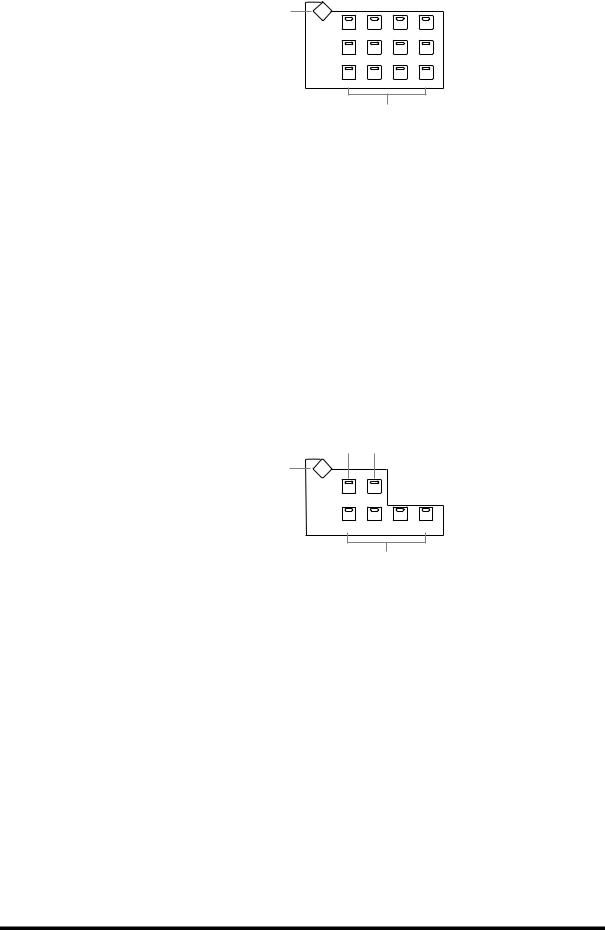
Control Surface |
23 |
AUX SELECT
1 |
AUX SELECT |
|
|
|
|
|
|
||
|
DISPLAY |
|
|
|
|
AUX 1 |
AUX 2 |
AUX 3 |
AUX 4 |
|
AUX 5 |
AUX 6 |
AUX 7 |
AUX 8 |
|
AUX 9 |
AUX 10 |
AUX 11 |
AUX 12 |
2
AAUX SELECT DISPLAY button
This button is used to select the following pages: Aux Send, Aux Send Pan, and Input Channel Aux View. See “Aux Sends” on page 110 for more information.
BAUX 1–12 buttons
These buttons are used to select Aux Sends when sending Input Channel signals to Aux Sends. The button indicator of the currently selected Aux Send lights up. If the currently selected Aux Send is paired, the indicator of its partner flashes. See “Aux Sends” on page 110 for more information.
Using these buttons along with the channel [ON] buttons enables you to turn Aux Sends on and off (Mix Minus) (page 117).
Using these buttons along with the LAYER buttons enables you to copy the corresponding channel levels to the Aux Send levels.
These buttons are also used to turn the Aux Out Solo function on and off when Aux/Solo Link is turned on (page 142).
ENCODER MODE
2 3
1 |
ENCODER MODE |
DISPLAY |
|
|
|
PAN |
AUX/ MTRX |
|
|
PAN |
SEND LEVEL |
|
|
ASSIGN 1 |
ASSIGN 2 |
ASSIGN 3 |
ASSIGN 4 |
INPUT |
OUTPUT |
SEND ASSIGN |
INSERT |
4
The small text labels below the ASSIGN buttons apply to the DAW Remote Layer. See “About Remote Layers” on page 253 for more information.
AENCODER MODE DISPLAY button
This button is used to select the Encoder Mode Assign page. See “Selecting Encoder Modes” on page 61 for more information.
BPAN button
This button is used to select the Pan Encoder mode. Its indicator lights up when this mode is selected. In this mode, the Encoders function as Pan controls when an Input Channel Layer is selected. When the Master Layer is selected, Encoders 21–24 function as Matrix Send Balance controls. The other Encoders are inactive. See “Selecting Encoder Modes” on page 61 for more information.
CAUX/MTRX button
This button is used to select the Aux/Mtrx Encoder mode. Its indicator lights up when this mode is selected. In this mode, the Encoders function as Aux Send level controls when an Input Channel Layer is selected. When the Master Layer is selected, Encoders 1–20 function as Matrix Send level controls. See “Selecting Encoder Modes” on page 61.
DM2000 Version 2—Owner’s Manual
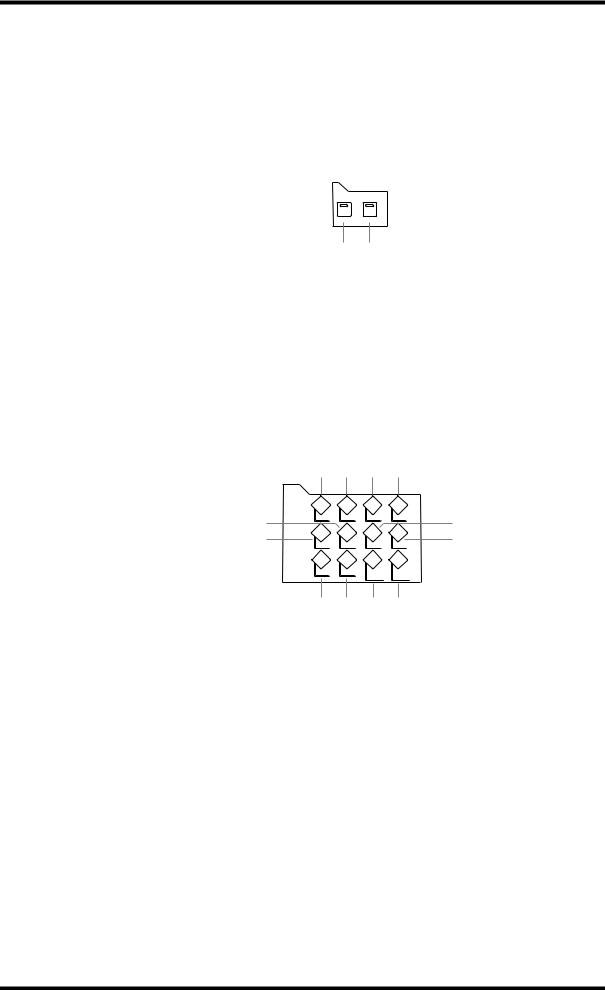
24 Chapter 2—Control Surface & Rear Panel
DASSIGN 1–4 buttons
These buttons are used to select the assignable Encoder modes. The button indicator for the currently selected mode lights up. When an assignable mode is selected, the function of the Encoders depends on the assigned parameter. Up to four parameters, from a list of 50, can be assigned to these four buttons. See “Assigning Parameters to the ENCODER MODE Assign Buttons” on page 62 for more information.
FADER MODE
FADER MODE
FADER AUX/ MTRX
1 2
AFADER button
This button selects Fader mode, in which the faders control Input or Output Channel levels, depending on the currently selected Layer. Its indicator lights up when this mode is selected. See “Selecting Fader Modes” on page 60 for more information.
BAUX/MTRX button
This button selects the Aux/Mtrx Fader mode, in which the faders control Aux Send or Matrix Send levels, depending on the currently selected Layer. Its indicator lights up when this mode is selected. See “Selecting Fader Modes” on page 60 for more information.
DISPLAY ACCESS
1 2 3 4
DISPLAY ACCESS
5 |
DATA |
DIO SETUP UTILITY |
7 |
|
|
||
6 |
MIDI |
REMOTE METER VIEW 8 |
|
|
PAIR |
GROUP INPUT OUTPUT |
|
|
|
PATCH PATCH |
|
|
9 J K L |
|
|
ADATA button
This button is used to select the Save, Load, and File pages, which are used to save and load DM2000 data to SmartMedia. See “Saving DM2000 Data to SmartMedia” on page 271 for more information.
BDIO button
This button is used to select the following pages: Word Clock Select, Dither, Cascade In, Cascade Out, Sampling Rate Converter, and Higher Sample Rate Data Transfer Format. See “Digital I/O & Cascading” on page 66 for more information.
CSETUP button
This button is used to select the following pages: Preferences 1, Preferences 2, Preferences 3, MIDI/TO HOST Setup, GPI Setup, Input Port Name, Output Port Name, Time Reference, Time Signature, Remote Port Setup, and Surround Bus Setup.
DUTILITY button
This button is used to select the following pages: Oscillator, Channel Status Monitor, Battery Check, and Operation Lock.
EREMOTE button
This button is used to select the Remote pages. See “About Remote Layers” on page 253 for more information.
DM2000 Version 2—Owner’s Manual

Control Surface |
25 |
FMIDI button
This button is used to select the following pages: MIDI Setup, Program Change Assign Table, Control Change Assign Table, and Bulk Dump. See “MIDI” on page 215 for more information.
GMETER button
This button is used to select the following pages: Input Channel Meter, Master Meter, Effect Input/Output Meter, Effect 1-8 Input/Output Meter, Effect 1–2 Input/Output Meter, Stereo Meter, and Metering Position. See “Metering” on page 127 for more information.
HVIEW button
This button is used to select the following pages: Parameter View, Fader View, and Channel Library. See “Viewing Channel Parameter Settings” on page 150, “Viewing Channel Fader Settings” on page 151, and “Channel Library” on page 166 for more information.
IPAIR button
This button is used to select the Input and Output Pair pages. See “Pairing Channels” on page 144 for more information.
JGROUP button
This button is used to select the following pages: Fader group, Mute group, Output Fader group, Output Mute group, Input Equalizer Link, Output Equalizer Link, Input Comp Link, Output Comp Link, Input Fader Group Master, and Output Fader Group Master.
KINPUT PATCH button
This button is used to select the following pages: Input Channel Patch, Input Channel Insert In Patch, Effects 1-2 Input/Output Patch, Effects 3–8 Input/Output Patch, Input Channel Name, and Input Patch Library. See “Input Patching” on page 77 for more information.
LOUTPUT PATCH button
This button is used to select the following pages: Slot Output Patch, Omni Out Patch, Output Insert In Patch, Input Channel Direct Out Destination, 2TR Out Digital Patch, Graphic Equalizer Insert, Output Channel Name, and Output Patch Library. See “Output Patching” on page 79 for more information.
DM2000 Version 2—Owner’s Manual
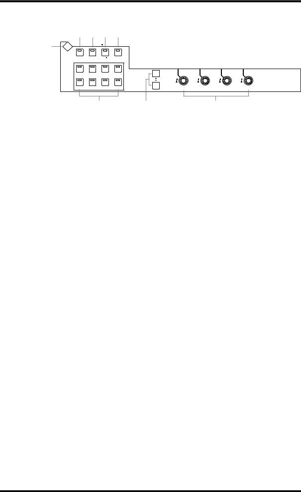
26 |
Chapter 2—Control Surface & Rear Panel |
|
|
|
|
||||
|
EFFECTS/PLUG-INS |
|
|
|
|
|
|||
|
|
2 3 4 5 |
|
|
|
|
|||
|
1 |
EFFECTS / PLUG INS |
|
|
|
|
|
||
|
|
DISPLAY |
|
|
|
|
|
|
|
|
|
INTERNAL |
GRAPHIC |
PLUG INS CHANNEL |
|
|
|
|
|
|
|
EFFECTS EQUALIZERS |
|
INSERTS |
|
|
|
|
|
|
|
1 |
2 |
3 |
4 |
|
|
|
|
|
|
5 |
6 |
7 |
8 |
1 |
2 |
3 |
4 |
|
|
|
6 |
7 |
|
|
8 |
|
|
AEFFECTS/PLUG-INS DISPLAY button
This button is used to select the following pages: Effects Edit, Effects Library, Graphic Equalizer Edit, Graphic Equalizer Library, Plug-In Setup, and Plug-In Edit. See “Internal Effects, Plug-Ins & GEQs” on page 174 for more information.
BINTERNAL EFFECTS button
This button is used to select the internal effects processors in conjunction with the EFFECTS/PLUG-INS [1–8] buttons. Its indicator lights up when it’s pressed. See “Editing Effects” on page 177 for more information.
CGRAPHIC EQUALIZERS button
This button is used to select the GEQs in conjunction with the EFFECTS/PLUG-INS [1–6] buttons. Its indicator lights up when it’s pressed. See “Editing GEQs” on page 183 for more information.
DPLUG-INS button
This button is used to select the Plug-Ins in conjunction with the EFFECTS/PLUG-INS [1–8] buttons. Its indicator lights up when it’s pressed. See “Editing Plug-Ins” on page 181 for more information.
ECHANNEL INSERTS button
If an internal effects processor or Y56K card effects chain is inserted in the currently selected channel, the relevant Effects Edit or Plug-In Edit page appears when this button is pressed, and its indicator lights up. In addition, the corresponding EFFECTS/PLUG-INS [1–8] button indicator flashes. If it’s a Y56K that is inserted, the [PLUG-INS] button indicator also flashes. If it’s an internal effects processor, the [INTERNAL EFFECTS] button indicator flashes. A warning message appears if there’s nothing inserted in the currently selected channel. See “Editing Effects” on page 177 and “Editing Plug-Ins” on page 181 for more information.
FEFFECTS/PLUG-INS 1–8 buttons
These buttons are used to select the internal effects processors, GEQs, and Plug-Ins in conjunction with the EFFECTS/PLUG-INS [INTERNAL EFFECTS], [GRAPHIC EQUALIZERS], and [PLUG-INS] buttons. The button indicator of the currently selected internal effects processor, GEQ, or Plug-In lights up. Since there are six GEQs, buttons [7] and [8] are inactive when the [GRAPHIC EQUALIZERS] button’s indicator is lit. When the EFFECTS/PLUG-INS [CHANNEL INSERTS] button indicator is lit, all of these buttons are inactive.
GParameter Up/Down buttons
These buttons are used to select the rows of internal effects processor and Plug-In parameters for editing with Parameter controls 1–4. The parameters in the currently selected row appear highlighted. Up to 16 parameters can be displayed at a time. If more are available, an up or down arrow is displayed. See “Editing Effects” on page 177 and “Editing Plug-Ins” on page 181 for more information.
DM2000 Version 2—Owner’s Manual
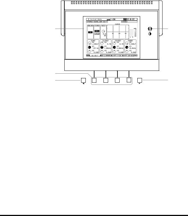
Control Surface |
27 |
HParameter controls 1–4
These are rotary controls and push switches. The rotary controls are used to edit the parameters of the currently selected internal effects processor, Plug-In, or GEQ. When the Effects Edit page is selected, they control the currently selected row of parameters, rows being selected by the Parameter Up/Down buttons. When the Graphic Equalizer Edit page is selected, Parameter control #1 selects the frequency bands and Parameter control #4 sets the gain of the selected band. Parameter controls #2 and #3 are inactive. See “Editing Effects” on page 177, “Editing Plug-Ins” on page 181, and “Editing GEQs” on page 183 for more information.
The push switches are used to punch the Effects or Plug-In parameters currently being controlled by the rotary controls in and out during Automix recording. See“Punching In & Out Individual Parameters” on page 207 for more information.
Display Section
1 |
2 |
3 |
|
4 |
5 |
F1 |
F2 F3 F4 |
ADisplay
This 320 x 240 dot display with fluorescent backlight displays pages, information on the currently selected Scene and channel, the sampling rate, and more. See “About the Display” on page 52 for more information.
BContrast control
This control is used to adjust the contrast of the display.
CF1–F4 buttons
These buttons are used to select the pages whose tabs are currently visible. See “Selecting Display Pages” on page 53 for more information.
DLeft Tab Scroll button
This button, which is active only when the left Tab Scroll arrow is displayed, is used to display the tabs of pages available to the left of the currently selected page. See “Selecting Display Pages” on page 53 for more information.
ERight Tab Scroll button
This button, which is active only when the right Tab Scroll arrow is displayed, is used to display the tabs of pages available to the right of the currently selected page. See “Selecting Display Pages” on page 53 for more information.
DM2000 Version 2—Owner’s Manual
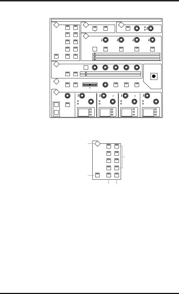
28 |
Chapter 2—Control Surface & Rear Panel |
|
|
|
|
|
|
|
||
|
SELECTED CHANNEL Section |
|
|
|
|
|
|
|
||
|
|
|
|
SELECTED CHANNEL |
|
|
|
|
||
|
|
ROUTING |
|
PHASE / INSERT |
|
DELAY |
|
|
||
|
DISPLAY |
|
DISPLAY |
|
|
DISPLAY |
FB |
|
|
|
|
|
|
|
MIX |
|
|
||||
|
|
1 |
2 |
|
|
|
|
|
|
|
|
|
|
INSERT ON |
|
ON |
TIME |
|
|
||
|
|
|
|
|
|
|
|
|||
|
|
|
|
|
|
|
|
|
|
|
|
|
|
|
AUX / MATRIX SEND |
|
|
|
|
|
|
|
|
3 |
4 |
|
|
|
|
|
|
|
|
|
|
DISPLAY |
|
|
|
|
|
|
|
|
|
5 |
6 |
|
LEVEL |
|
LEVEL |
LEVEL |
LEVEL |
|
|
|
|
|
|
|
|
|
|
||
|
|
7 |
8 |
BANK |
ON |
|
ON |
ON |
ON |
|
|
|
|
|
|
AUX 1/ MATRIX 1 |
AUX 2/ MATRIX 2 |
AUX 3/ MATRIX 3 |
AUX 4/ MATRIX 4 |
||
|
|
|
|
|
AUX 5 |
|
AUX 6 |
AUX 7 |
AUX 8 |
|
|
FOLLOW PAN |
STEREO |
DIRECT |
|
AUX 9 |
|
AUX 10 |
AUX 11 |
AUX 12 |
|
|
|
DYNAMICS |
|
|
|
|
|
|
|
|
|
DISPLAY |
|
|
|
|
|
|
|
|
|
|
|
|
GATE / COMP |
|
|
|
|
|
|
|
|
|
|
GATE |
THRESHOLD |
RANGE |
ATTACK |
DECAY |
HOLD |
|
|
|
|
|
COMP |
THRESHOLD |
RATIO |
ATTACK |
RELEASE |
GAIN |
|
|
|
|
GATE ON |
COMP ON |
|
|
|
|
|
|
|
|
|
PAN / SURROUND |
|
|
|
|
|
|
|
|
|
DISPLAY |
|
L |
R |
|
|
|
|
|
|
|
|
ODD |
EVEN |
|
|
|
|
|
||
|
|
|
LINK |
GRAB |
EFFECT |
|
|
|||
|
|
L |
R |
|
|
|
|
|||
|
|
EQUALIZER |
|
|
|
|
|
|
|
|
|
DISPLAY |
|
|
LOW |
LOW MID |
|
HIGH MID |
HIGH |
||
|
CHANNEL |
ATT. |
FREQUENCY |
|
FREQUENCY |
|
FREQUENCY |
FREQUENCY |
|
|
|
|
|
|
|
||||||
|
|
|
Q |
|
Q |
|
Q |
|
Q |
|
|
|
|
|
GAIN |
|
GAIN |
|
GAIN |
GAIN |
|
|
COPY |
EQ ON |
|
dB |
|
dB |
|
dB |
|
dB |
|
|
|
125 |
1.00 |
4.00 |
10.0 |
||||
|
|
|
Hz |
Hz |
Hz |
Hz |
||||
|
PASTE |
|
|
kHz |
|
kHz |
|
kHz |
|
kHz |
|
|
|
|
|
|
|
|
|
|
|
The subsections of the SELECTED CHANNEL section are explained below.
ROUTING
1 |
ROUTING |
|
|
|
|
|
|
|
DISPLAY |
|
|
|
1 |
2 |
|
|
3 |
4 |
5 |
|
5 |
6 |
|
|
7 |
8 |
|
2 |
FOLLOW PAN STEREO |
DIRECT |
|
|
|
3 4
AROUTING DISPLAY button
This button is used to select the following pages: Input Channel Routing, Bus to Stereo, and Bus to Stereo Library. See “Routing Input Channels” on page 93 and “Sending Bus Outs to the Stereo Out” on page 109 for more information.
BFOLLOW PAN button
This button determines whether or not the currently selected Input Channel’s pan setting, and Surround pan setting are applied to the Bus Outs. Its indicator lights up when it’s pressed. See “Routing Input Channels” on page 93 for more information.
CSTEREO button
This button is used to route the currently selected Input Channel to the Stereo Out. Its indicator lights up when it’s pressed. See “Routing Input Channels” on page 93 for more information.
DDIRECT button
This button is used to route the currently selected Input Channel to its Direct Out. Its indicator lights up when it’s pressed. See “Routing Input Channels” on page 93 for more information.
DM2000 Version 2—Owner’s Manual
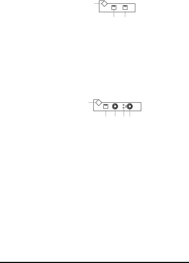
Control Surface |
29 |
EROUTING 1–8 buttons
These buttons are used to route the currently selected Input Channel to the Bus Outs. The button indicators of Bus Outs to which the Input Channel is routed light up. See “Routing Input Channels” on page 93 for more information.
PHASE/INSERT
1 |
PHASE / INSERT |
|
|
|
DISPLAY |
|
INSERT ON |
2 3
APHASE/INSERT DISPLAY button
This button is used to select the Input Channel Phase and Insert pages. See “Reversing the Signal Phase” on page 84 and “Using Inserts” on page 135 for more information.
BPhase [ ] button
This button is used to reverse the signal phase of the currently selected Input Channel. Its indicator lights up when the phase is reversed. See “Reversing the Signal Phase” on page 84 for more information.
CINSERT ON button
This button is used to turn on and off the Insert of the currently selected channel. Its indicator lights up when the Insert is on. See “Using Inserts” on page 135 for more information.
DELAY
1 |
DELAY |
|
|
|
|
|
DISPLAY |
FB |
|
MIX |
|
|
|
|
|
ON |
TIME |
|
|
2 3 45
ADELAY DISPLAY button
This button is used to select the Delay pages. See “Delaying Channel Signals” on page 141 for more information.
BON button
This button is used to turn on and off the Delay of the currently selected channel. Its indicator lights up when the Delay function is on. See “Delaying Channel Signals” on page 141 for more information.
CTIME control
This control is used to set the delay time of the currently selected channel’s Delay function. See “Delaying Channel Signals” on page 141 for more information.
DFB/MIX indicators
These indicators show whether the FB/MIX control is set to control Feedback Gain or Feedback Mix. The FB indicator lights up when it’s set to control Feedback Gain; the MIX indicator, when its set to control Feedback Mix. See “Delaying Channel Signals” on page 141 for more information.
EFB/MIX control
This is a rotary control and push switch. When the currently selected channel is an Input Channel, the push switch can be used to select either Feedback Gain (FB) or Feedback Mix (MIX). The rotary control is used to set the Feedback Gain or Feedback Mix, as selected by the push switch. See “Delaying Channel Signals” on page 141 for more information.
DM2000 Version 2—Owner’s Manual
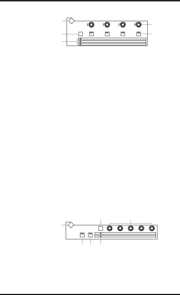
30 Chapter 2—Control Surface & Rear Panel
AUX/MATRIX SEND
1 |
AUX / MATRIX SEND |
|
|
|
|
|
|
|
|
|
DISPLAY |
|
|
4 |
|
LEVEL |
LEVEL |
LEVEL |
LEVEL |
2
3
5
BANK |
ON |
ON |
ON |
ON |
|
AUX 1/ MATRIX 1 |
AUX 2/ MATRIX 2 |
AUX 3/ MATRIX 3 |
AUX 4/ MATRIX 4 |
|
AUX 5 |
AUX 6 |
AUX 7 |
AUX 8 |
|
AUX 9 |
AUX 10 |
AUX 11 |
AUX 12 |
AAUX/MATRIX SEND DISPLAY button
The pages selected by this button depends on the type of channel currently selected. If it’s an Input Channel, it selects the Aux Send, Aux Send Pan, and Input Channel Aux View pages. If it’s an Output Channel, it selects the Matrix Send, Matrix Send Pan, and Matrix View pages.
BBANK button
This button is used to select Aux 1–4/Matrix 1–4, Aux 5–8, or Aux 9–12 for use with the AUX/MATRIX LEVEL controls and [ON] buttons. When an Output Channel is selected, the Aux 1–4/Matrix 1–4 bank is selected automatically and cannot be changed. See “Using the SELECTED CHANNEL AUX/MATRIX SEND LEVEL Controls” on page 111 for more information.
CBank indicators
These indicators show which bank of Aux/Matrix Sends has been selected by the [BANK] button. When an Output Channel is selected, the Aux 1–4/Matrix 1–4 bank is selected automatically and cannot be changed.
DLEVEL controls
These controls are used to set the levels of the Aux or Matrix Send currently selected by the [BANK] button. If the currently selected channel is an Input Channel, they control Aux Send levels. If it’s a Bus Out, Aux Send, or the Stereo Out, they control Matrix Send levels. See “Setting Aux Send Levels” on page 111 and “Setting Matrix Send Levels” on page 121 for more information.
EON buttons
These buttons are used to mute the Aux/Matrix Sends currently selected by the [BANK] button. The button indicators of channels that are on light up. If the currently selected channel is an Input Channel, they mute Aux Sends. If the currently selected channel is a Bus Out, Aux Send, or the Stereo Out, they mute Matrix Sends. See “Muting Aux Sends (ON/OFF)” on page 112 and “Muting Matrix Sends (ON/OFF)” on page 122 for more information.
DYNAMICS
|
2 |
|
|
3 |
|
|
1 |
DYNAMICS |
|
|
|
|
|
|
DISPLAY |
|
|
|
|
|
|
GATE / COMP |
|
|
|
|
|
|
GATE |
THRESHOLD |
RANGE |
ATTACK |
DECAY |
HOLD |
|
COMP |
THRESHOLD |
RATIO |
ATTACK |
RELEASE |
GAIN |
|
GATE ON COMP ON |
|
|
|
|
|
4 5 6
ADYNAMICS DISPLAY button
This button is used to select the following pages: Gate Edit, Gate Library, Comp Edit, and Comp Library. See “Gating Input Channels” on page 85 and “Compressing Channels” on page 137 for more information.
DM2000 Version 2—Owner’s Manual
 Loading...