


 Loading...
GUITAR AMPLIFIER AMPLIFICATEUR DE GUITARE GITARRENVERSTÄ RKER AMPLIFICADOR DE GUITARRA AMPLIFICATORE PER CHITARRA GITAAR VERSTERKER


Owner’s Manual
Mode d’emploi
Bedienungsanleitung
Manual del Usuario
Manuale di Istruzioni
Handleiding
FCC INFORMATION (U.S.A.)
tion of other electronic devices. Compliance with FCC regula- |
uted by Yamaha Corporation of America or its subsidiaries. |
1. IMPORTANT NOTICE: DO NOT MODIFY THIS UNIT! |
tions does not guarantee that interference will not occur in all |
This product, when installed as indicated in the instructions |
installations. If this product is found to be the source of inter- |
contained in this manual, meets FCC requirements. Modifica- |
ference, which can be determined by turning the unit “OFF” |
tions not expressly approved by Yamaha may void your au- |
and “ON”, please try to eliminate the problem by using one of |
thority, granted by the FCC, to use the product. |
the following measures: |
2. IMPORTANT: When connecting this product to accessories |
Relocate either this product or the device that is being af- |
and/or another product use only high quality shielded cables. |
fected by the interference. |
Cable/s supplied with this product MUST be used. Follow all |
Utilize power outlets that are on different branch (circuit |
installation instructions. Failure to follow instructions could |
breaker or fuse) circuits or install AC line filter/s. |
void your FCC authorization to use this product in the USA. |
In the case of radio or TV interference, relocate/reorient the |
3. NOTE: This product has been tested and found to comply |
antenna. If the antenna lead-in is 300 ohm ribbon lead, |
with the requirements listed in FCC Regulations, Part 15 for |
change the lead-in to co-axial type cable. |
Class “B” digital devices. Compliance with these require- |
If these corrective measures do not produce satisfactory |
ments provides a reasonable level of assurance that your use |
results, please contact the local retailer authorized to distrib- |
of this product in a residential environment will not result in |
ute this type of product. If you can not locate the appropriate |
harmful interference with other electronic devices. This |
retailer, please contact Yamaha Corporation of America, |
equipment generates/uses radio frequencies and, if not in- |
Electronic Service Division, 6600 Orangethorpe Ave, Buena |
stalled and used according to the instructions found in the |
Park, CA90620 |
users manual, may cause interference harmful to the opera- |
The above statements apply ONLY to those products distrib- |
|
|
|
|
* This applies only to products distributed by YAMAHA CORPORATION OF AMERICA. |
|
IMPORTANT NOTICE FOR THE UNITED KINGDOM
Connecting the Plug and Cord
WARNING: THIS APPARATUS MUST BE EARTHED IMPORTANT. The wires in this mains lead are coloured in accordance with the following code:
GREEN-AND-YELLOW : EARTH
BLUE |
: NEUTRAL |
BROWN |
: LIVE |
As the colours of the wires in the mains lead of this apparatus may not correspond with the coloured markings identifying the terminals in your plug proceed as follows:
The wire which is coloured GREEN-and-YELLOW must be connected to the terminal in the plug which is marked by the letter E or by the safety earth symbol or colored GREEN or GREEN-and-YELLOW.
The wire which is coloured BLUE must be connected to the terminal which is marked with the letter N or coloured BLACK.
The wire which is coloured BROWN must be connected to the terminal which is marked with the letter L or coloured RED.
The exclamation point within the equilateral triangle is intended to alert the user to the presence of important operating and maintenance (servicing) instructions in the literature accompanying the product.
The lightning flash with arrowhead symbol, within the equilateral triangle, is intended to alert the user to the presence of uninsulated “dangerous voltage” within the product’s enclosure that may be of sufficient magnitude to constitute a risk of electrical shock.
• This applies only to products distributed by Yamaha-Kemble Music (U.K.) Ltd.
2

IMPORTANT SAFETY INSTRUCTIONS
INFORMATION RELATING TO PERSONAL INJURY, ELECTRICAL SHOCK, AND FIRE HAZARD POSSIBILITIES HAS BEEN INCLUDED IN THIS LIST.
WARNING- When using any electrical or electronic product, basic precautions should always be followed. These precautions include, but are not limited to, the following:
1. Read all Safety Instructions, Installation Instructions, Special Message Section items, and any Assembly Instructions found in this manual BEFORE making any connections, including connection to the main supply.
2. Do not attempt to service this product beyond that described in the user-maintenance instructions. All other servicing should be referred to qualified service personnel.
3. Main Power Supply Verification: Yamaha products are manufactured specifically for the supply voltage in the area where they are to be sold. If you should move, or if any doubt exists about the supply voltage in your area, please contact your dealer for supply voltage verification and (if applicable) instructions. The required supply voltage is printed on the name plate. For name plate location, please refer to the graphic found in the Special Message Section of this manual.
4. DANGER-Grounding Instructions: This product must be grounded and therefore has been equipped with a three pin attachment plug. If this product should malfunction, the ground pin provides a path of low resistance for electrical current, reducing the risk of electrical shock. If your wall socket will not accommodate this type plug, contact an electrician to have the outlet replaced in accordance with local electrical codes. Do NOT modify the plug or change the plug to a different type!
5. WARNING: Do not place this product or any other objects on the power cord or place it in a position where anyone could walk on, trip over, or roll anything over power or connecting cords of any kind. The use of an extension cord is not recommended! If you must use an extension cord, the minimum wire size for a 25' cord (or less) is 18 AWG. NOTE: The smaller the AWG number, the larger the current handling capacity. For longer extension cords, consult a local electrician.
6. Ventilation: Electronic products, unless specifically designed for enclosed installations, should be placed in locations that do not interfere with proper ventilation. If instructions for enclosed installations are not provided, it must be assumed that unobstructed ventilation is required.
7. Temperature considerations: Electronic products should be installed in locations that do not seriously contribute to their operating temperature. Placement of this product close to heat sources such as; radiators, heat registers etc., should be avoided.
8. This product was NOT designed for use in wet/damp locations and should not be used near water or exposed to rain. Examples of wet /damp locations are; near a swimming pool, spa, tub, sink, or wet basement.
9. This product should be used only with the components supplied or; a cart ,rack, or stand that is recommended by the manufacturer. If a cart, rack, or stand is used, please observe all safety markings and instructions that accompany the accessory product.
10. The power supply cord (plug) should be disconnected from the outlet when electronic products are to be left unused for extended periods of time. Cords should also be disconnected when there is a high probability of lightening and/or electrical storm activity.
11. Care should be taken that objects do not fall and liquids are not spilled into the enclosure through any openings that may exist.
12. Electrical/electronic products should be serviced by a qualified service person when:
a.The power supply cord has been damaged; or
b.Objects have fallen, been inserted, or liquids have been spilled into the enclosure through openings; or
c.The product has been exposed to rain; or
d.The product does not operate, exhibits a marked change in performance; or
e.The product has been dropped, or the enclosure of the product has been damaged.
13.This product, either alone or in combination with an amplifier and headphones or speaker/s, may be capable of producing sound levels that could cause permanent hearing loss. DO NOT operate for a long period of time at a high volume level or at a level that is uncomfortable. If you experience any hearing loss or ringing in the ears, you should consult an audiologist.
IMPORTANT: The louder the sound, the shorter the time period before damage occurs.
14. Some Yamaha products may have benches and/or accessory mounting fixtures that are either supplied as a part of the product or as optional accessories. Some of these items are designed to be dealer assembled or installed. Please make sure that benches are stable and any optional fixtures (where applicable) are well secured BEFORE using. Benches supplied by Yamaha are designed for seating only. No other uses are recommended.
PLEASE KEEP THIS MANUAL
92-469-3 |
3 |

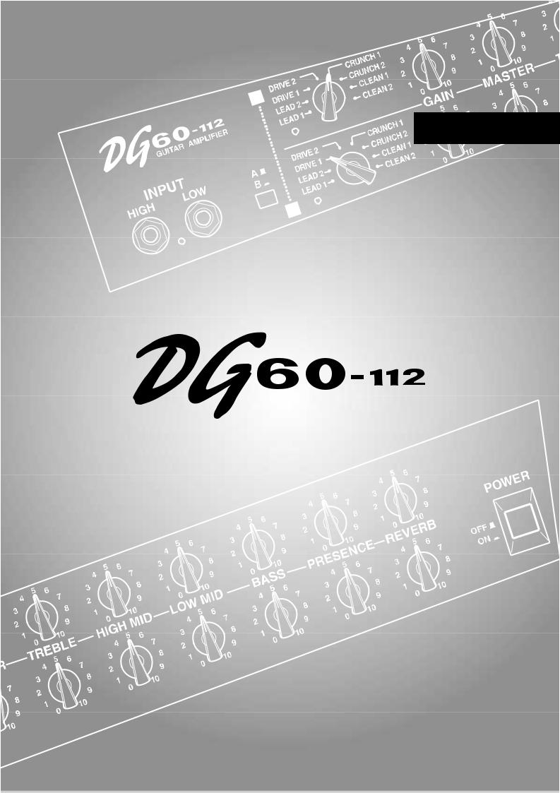
Thank you for purchasing a Yamaha DG60-112 Guitar Amplifier.
Originally conceived and entirely designed by Yamaha, the DG60-112 is a digital guitar amplifier that delivers powerful tube amp tone with superior stability compared to other tube amplifiers.
Equipped with 2 independent channels, each channel offers 8 different preset amp types from which you can choose and create tone with. Along with digital spring reverb that can be applied to each channel is capable of producing a wide range of tone. Foot switches connected to the foot switch jacks can be used to switch between channels and switch the reverb ON/OFF. It also features a line out jack equipped with a speaker simulator. Altogether, the DG60-112 is a versatile guitar amplifier that can be used in studio as well as live situations.
To get the best results and longest life out of your DG60-112, we recommend that you carefully read this manual, and keep it in a safe place for future reference.
|
Contents |
Precautions ........................................................................... |
5 |
Specifications ........................................................................ |
5 |
The Panel Controls ............................................................... |
6 |
■ Front Panel ........................................................................................ |
6 |
■ Rear Panel ......................................................................................... |
7 |
Setting Examples .................................................................. |
8 |
4

Precautions
●Avoid using your amplifier in the following locations to prevent possible damage:
•In direct sunlight or next to heating equipment.
•Extremely cold or hot locations.
•Locations exposed to high humidity or excessive dust.
•Locations subject to strong shocks or vibration.
●Before making any connections, make sure that the power on the amplifier and any external devices is switched OFF.
●To protect the speaker from possible damage, always set the MASTER knob to “0” before switching the power ON/OFF.
●When connecting a speaker to this unit make sure to turn OFF the power first.
●Do not apply excessive force to the switches and controls.
●Your Yamaha guitar amplifier is a precision musical instrument. Handle it with care and avoid dropping or bumping it.
●Operating temperatures will rise during use. Make sure the amplifier is used in a well-ventilated area. The DG60-112 should be placed in a position were there is at least 30cm (12”) clearance from the wall on the sides, top and back of the amplifier.
●For safety, always remove the power plug from the AC wall outlet if there is any danger of lightning striking in your area.
●Keep the amplifier away from neon signs or fluorescent lighting to prevent noise pickup.
●To prevent damage and possibly electrical shock, never open the case and tamper with the internal circuitry.
●Never use benzene, thinner or other volatile liquids for cleaning, as these chemicals may cause damage or discoloration to the finish. Always use a dry, soft cloth to wipe off dust and dirt.
Specifications
Digital Section
Complete Digital Signal Processing
Amplification Type : Internal 8 Channel Preset
Digital Reverb (SPRING)
Speaker Simulator (LINE OUT)
Analog Section
60W Solid State Power Amp
30 cm Speaker (EMINENCE) x 1
Controller/Switch
Front Panel : GAIN, MASTER, TREBLE, HIGH MID, LOW MID, BASS, PRESENCE, REVERB, AMP select switch, for each channel (A/B), Channel select switch (A/B)
Rear Panel : EFFECT BLEND, SP MUTE switch, for each channel (A/B), EFFECT SEND/RETURN level switch
Indicator
Peak Level Display LED (Red)
Connection Jacks
INPUT HIGH/LOW, EFFECT SEND/RETURN, LINE OUT/
PHONES, FOOT SW (CH SELECT, REVERB)
: All Standard Phone Mono Jack
A/D Converter |
20 bit + 3 bit floating |
D/A Converter |
20 bit |
Sampling Frequency |
48 kHz |
Input Level/Impedance
INPUT HIGH: –20dBm (THRU)/1MΩ
INPUT LOW: –10dBm (THRU)/1MΩ
EFFECT RETURN: 0dBm/120kΩ
Output Level/Impedance
SPEAKER: 60W RMS/8Ω
LINE OUT: +2dBm/47Ω
EFFECT SEND: –2dBm/1kΩ
Power Requirements
U.S. and Canadian models : 120V, 60Hz General model : 230V, 50Hz
Power Consumption
70W
Dimensions (W x H x D)
540 x 504 x 276 mm (21.3” x 19.8” x 10.9”)
Weight
18.0 kg (39 lbs 11 oz)
*Specifications and external appearance are subject to change without notice.
5

The Panel Controls
■ Front Panel
|
|
|
q |
r t |
y u |
|
|
|
|
|
i |
|
|
|
|
|
|
|
o |
|||||||||||
|
|
|
|
|
|
|
|
|
|
|
|
|
|
|
|
|
|
|
|
|
|
|
|
|
|
|
|
|
|
|
|
|
|
|
|
|
|
|
|
|
|
|
|
|
|
|
|
|
|
|
|
|
|
|
|
|
|
|
|
|
|
|
|
|
|
|
|
|
|
|
|
|
|
|
|
|
|
|
|
|
|
|
|
|
|
|
|
|
|
|
|
|
|
|
|
|
|
|
|
|
|
|
|
|
|
|
|
|
|
|
|
|
|
|
|
|
|
|
|
|
|
|
|
|
|
|
|
|
|
|
|
|
|
|
|
|
|
|
|
|
|
|
|
|
|
|
|
|
|
|
|
|
|
|
|
|
|
|
|
|
|
|
|
|
|
|
|
|
|
|
|
|
|
|
|
|
|
|
|
|
|
|
|
|
|
|
|
|
|
|
|
|
|
|
|
|
|
|
|
|
|
|
|
|
|
|
|
|
|
|
|
|
|
|
|
|
|
|
|
|
|
|
|
|
|
|
|
|
|
|
|
|
|
|
|
|
|
|
|
|
|
|
|
|
|
|
|
|
|
|
|
|
|
|
|
|
|
|
|
|
|
|
|
|
|
|
|
|
|
|
|
|
|
|
|
|
|
|
w |
e |
!0 |
The DG60-112 is a high-quality guitar amp with 2 independent channels.
You can switch between channel A (the upper row of knobs t-o) settings and channel B (the lower row of knobs t-o) with the switch e or with a foot-switch. Control knobs t-o for both channels A and B operate in the same manner.
q Input Jack (INPUT HIGH, LOW)
The amplifier’s input jack.
The guitar is connected to the amplifier here. Guitars with a high output should be connected to the LOW jack while guitars with a low output should be connected to the HIGH jack. If you want a clean tone we recommend connecting the guitar to the LOW jack.
* Always switch the power off before connecting the guitar.
w Peak Indicator
This indicator is used to match the input level. The indicator lights when the peak level is exceeded.
e Channel Select Switch
Use to switch between Channels A and B.
Press the switch to select the channel you want to use.
When Channel A (  ) is selected, the amplifier will produce tone according to the settings specified by the upper row of knobs t – o. When
Channel B(  ) is selected, the amplifier will produce tone according to the settings specified by the lower row of knobs t – o.
r Channel Indicator
The indicator lamp corresponding to the currently selected channel lights.
t Amp Select Switch
Use to select one of the 8 internal preset guitar amp types. With any of the amp types, basically 2 is brighter than 1.
Depending upon the control settings, as shown in “Setting Examples” on the page 8, the tone character that is possible is wider than what the amp type’s name implies.
•LEAD1, LEAD2
Lead offers a tone with heavy distortion. Substantial mids provide a fat tone with excellent sustain.
•DRIVE1, DRIVE2
Drive offers a thick overdrive tone with excellent sustain similar to when the volume is fully raised on a tube amplifier. Using the tone control knobs to adjust the balance of their respective frequencies creates a wider variety of tone.
•CRUNCH1, CRUNCH2
Crunch offers expressive picking articulation and nuance. Raise the
GAIN level creates a tone similar to that natural overdrive when the volume is raised on a tube amplifier. This crisp tone is excellent for playing riffs and rhythm parts.
•CLEAN1, CLEAN2
A clean sound without distortion. Use an effect such as reverb or chorus to create a spacious sound.
y Gain Volume (GAIN)
Use to control the amount of distortion.
Rotate the knob to the right to increase the amount of distortion.
*If the GAIN is set to “0”, sound will not be produced even of the MASTER Volume is turned up.
u Master Volume (MASTER)
Use to control the overall volume of the GAIN and tone control settings.
i Tone Controls
(TREBLE, HIGH MID, LOW MID, BASS, PRESENCE)
Use to control the levels of their respective frequencies.
Rotate the knob to the right to increase the level of tone.
TREBLE Controls the level of the high frequencies.
HIGH MID Controls the level of the upper mid frequencies.
LOW MID Controls the level of the lower mid frequencies.
BASS Controls the level of the low frequencies. PRESENCE Controls the level of the frequencies higher than
TREBLE.
o Reverb Volume (REVERB)
Use to control the amount of reverb (Spring Reverb).
Rotate the knob to the right to increase the amount of reverb. If the knob is set to “0”, no reverb will be produced.
Reverb can also be switched ON/OFF with a foot switch connected to the FOOT SW REVERB jack located on the rear panel.
!0Power Switch (POWER)
The main unit’s power switch.
Press the switch to turn the amp ON/OFF.
*To protect the speakers make sure the MASTER Volume is set to “0”before you switch the power ON/OFF.
6
The Panel Controls
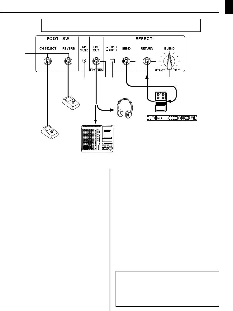
■ Rear Panel
Before making any connections, make sure that the power on the DG60-112 and any external devices is switched OFF.
!1
!2 |
!3!4 |
!5 |
!6 !7 |
OUT IN
Reverb on/off
Headphones
Effect Unit
Channel A/B selection
P. A. Mixer or Recording Device
!1Foot Switch (FOOT SW)
The following functions can be switched with an optional foot switch
(Yamaha FS1, etc.) connected to these jacks.
•Channel Select (CH SELECT)
You can easily switch between Channels A and B in the same manner as the Channel Select Switch e on the front panel.
Step on the foot switch to switch between Channels A/B.
*When the foot switch is used, the Channel Select Switch e on the front panel is inactive.
•Reverb (REVERB)
You can switch the Reverb ON/OFF.
Stepping on the foot switch switches the Reverb ON/OFF. When the Reverb is switched OFF, no reverb will be produced.
!2Speaker Mute Switch (SP MUTE)
Press the switch to mute output from the speaker. Insert a thin object inside the hole to press the switch.
Use this switch in conjunction with the headphones or Line Out when you don’t want sound produced by the DG60-112’s speaker.
*When speaker output is muted, output to the EFFECT SEND jack !5will be muted as well.
!3Line Out/Head Phone Jack (LINE OUT/PHONES)
Use this jack to connect directly to a mixer’s line jack or use a pair of
headphones.
The line signal from this jack passes through a *speaker simulator.
!4Effect Send/Return Level Switch (0dB/-20dB)
The output level of the Send Jack !5and the input level of the Return
Jack !6can be set to –20dB or 0dB.
!5Effect Send Jack (EFFECT SEND)
Connect an external effector’s input jack to this jack.
*When speaker output is muted, output to the EFFECT SEND jack !5will be muted as well.
!6Effect Return Jack (RETURN)
Connect an external effector’s output jack to this jack.
!7Blend Knob (BLEND)
Use this knob to control the amount of signal that is received from the effect return and added to the DG60-112’s amp signal.
Rotate the knob toward the EFFECT side to add more effect to the tone. Rotate the knob toward the DRY side for tone without effect.
* What is a Speaker Simulator?
The speaker simulator adds the live nuance of a speaker to the line signal.
When you connect the DG60-112 directly to a mixer or MTR the speaker simulator will add the acoustic characteristics of a speaker, as heard through a microphone, to the tone.
7

Setting Examples
To help you start enjoying the fantastic sound of the DG60-112, here are some examples of common settings. Use these as a starting point in creating your own original sounds.
*Set the Master Volume control to a suitable level.
*The setting can be changed to suit the guitar you use. Find your optimum setting by referring to the sample settings.
A typical distortion sound often used in British hard rock.
All-round crunch sound.
LEAD1 10.0 – 10.0 5.8 1.9 10.0 10.0 5.5 CRUNCH1 9.3 – 9.3 9.0 8.1 3.9 7.4 5.1
Ideally smooth lead sound for solos with sustains using |
The warm and clean sound of a crunch amp. Can be used |
|||
the front pickup. |
|
for all genres from jazz to rock. |
||
LEAD1 10.0 – |
10.0 6.8 8.7 10.0 10.0 5.1 |
CRUNCH1 3.5 |
– |
7.0 4.0 2.0 3.0 4.0 4.0 |
A brilliant sound suitable for hard rock and heavy metal.
Crunch sound like a low-power vintage amp with the volume turned up all the way.
LEAD2 9.0 – 5.0 6.4 2.0 6.5 5.0 4.0 CRUNCH2 3.0 – 9.3 4.7 1.6 6.5 7.3 3.4
Optimum distortion for heavy riffs with the gain up, crisp |
Contemporary jazz sound. Can be used to obtain a clean |
|||
overdrive with the gain down. |
sound without using the CLEAN channel. |
|||
LEAD2 3~8 – |
7.0 2.0 2.0 5.5 7.0 3.0 |
CRUNCH2 2.6 |
– |
2.7 7.5 9.2 7.3 1.7 4.2 |
Tight overdrive sound.
|
|
|
|
|
|
|
|
|
|
|
|
|
|
|
|
|
|
|
|
DRIVE1 10.0 |
– |
9.7 |
|
|
1.5 |
8.2 |
7.5 |
6.5 |
4.0 |
||||||||||
A punchy overdrive sound with rich overtones in the mid range.
|
|
|
|
|
|
|
|
|
|
|
|
|
|
|
|
|
|
|
|
DRIVE1 |
8.7 |
|
– |
7.0 |
|
|
7.5 |
7.5 |
7.4 |
7.1 |
4.2 |
||||||||
A hard overdrive sound emphasizing the low and high ranges.
|
|
|
|
|
|
|
|
|
|
|
|
|
|
|
|
|
|
|
|
DRIVE2 10.0 |
– |
9.2 |
|
|
8.5 |
4.0 |
7.3 |
5.6 |
4.4 |
||||||||||
Texas blues type sound with slight overdrive.
Country sound with a punch.
|
|
|
|
|
|
|
|
|
|
|
|
|
|
|
|
|
|
|
|
CLEAN1 5.4 |
|
– |
10.0 8.2 8.9 |
8.1 |
5.8 4.7 |
||||||||||||||
A rich and clean bass sound used in hard rock.
|
|
|
|
|
|
|
|
|
|
|
|
|
|
|
|
|
|
|
|
CLEAN1 5.3 |
|
– |
5.7 |
|
|
0.9 3.0 |
9.5 |
9.9 3.1 |
|||||||||||
A bright, clean sound. Can be used widely in a number of scenes.
|
|
|
|
|
|
|
|
|
|
|
|
|
|
|
|
|
|
|
|
CLEAN2 5.4 |
|
– |
7.2 |
|
|
8.3 10.0 4.9 |
5.0 3.2 |
||||||||||||
The natural, light crunch sound of a clean amp with the volume up.
|
|
|
|
|
|
|
|
|
|
|
|
|
|
|
|
|
|
|
|
|
|
|
|
|
|
|
|
|
|
|
|
|
|
|
|
|
|
|
|
DRIVE2 4.9 |
|
– |
7.0 |
|
|
7.0 8.1 |
7.7 |
9.0 3.2 |
CLEAN2 10.0 – |
4.9 |
|
|
5.3 8.6 |
3.9 |
3.6 4.1 |
||||||||||||||||||||||||
8
Mode d’emploi |
AMPLIFICATEUR DE GUITARE |

Nous vous remercions d’avoir fait l’acquisition de l’amplificateur de guitare DG60-112
Yamaha.
Conçu initialement et entièrement réalisé par Yamaha, le DG60-112 est un amplificateur de guitare numérique capable de délivrer des sons tout aussi puissants que ceux des amplificateurs à lampes tout en offrant une stabilité de fonctionnement supérieure comparée à celle des autres types d’amplificateurs à lampes. Doté de 2 canaux indépendants, chacun des canaux offre un choix de huit différents préréglages d’amplification qui vous permettent de choisir et de créer une grande variété de sons originaux. Les interrupteurs au pied raccordés aux prises d’interrupteur au pied permettent d’effectuer une commutation entre les canaux et d’activer ou de désactiver la réverbération. L’amplificateur de guitare se présente également avec une prise de sortie de ligne équipée d’un simulateur de haut-parleur. Le DG60-112 dans son intégralité est un amplificateur de guitare d’une grande souplesse qui lui permet d’être utilisé autant dans un studio qu’à l’occasion de concerts.
Pour avoir la certitude d’obtenir les meilleurs résultats possibles et assurer à votre DG60-
112 une longévité optimale, nous vous recommandons de lire attentivement ce mode d’emploi et par ailleurs, de le conserver dans un endroit sûr à des fins de consultation ultérieure.
Table des matières |
|
Précautions d’usage ........................................................... |
11 |
Fiche technique ................................................................... |
11 |
Commandes en façade ....................................................... |
12 |
■ Façade ............................................................................................. |
12 |
■ Face arrière ..................................................................................... |
13 |
Exemples de réglages ........................................................ |
14 |
10
Précautions d’usage
●Pour éviter tout risque d’endommagement de votre amplificateur, évitez de vous en servir dans les endroits mentionnés ci-dessous :
•En plein soleil ou près d’un appareil de chauffage.
•Dans les lieux à température extrême, basse comme élevée.
•Dans les lieux à très forte humidité ou excessivement poussérieux.
•Dans les lieux soumis à des chocs violents ou de fortes vibrations.
●Avant d’effectuer le moindre branchement, vérifiez que l’alimentation du DG60-112 et de tous les appareils extérieurs est bien coupée.
●Par mesure de précaution et de façon à ne pas endommager les haut-parleurs, positionnez toujours le potentiomètre de réglage de niveau de sortie MASTER sur “0” avant de mettre l’appareil sous tension ou de l’arrêter.
●N’oubliez pas de couper l’alimentation de l’amplificateur au préalable avant de raccorder un haut-parleur.
●Ne forcez jamais sur les commutateurs et les commandes de réglage.
●Notez que la température des appareils croît au fur et à mesure de leur utilisation. Par conséquent, vous devez vous assurer que l’amplificateur est utilisé dans un endroit bien aéré. Le DG60-112 doit être disposé de telle sorte qu’un espace d’au moins 30 cm soit aménagé entre le mur et l’appareil, autant sur les côtés, au-dessus que derrière l’amplificateur.
●Votre amplificateur de guitare Yamaha est un instrument musical de haute précision. Vous devez le manipuler délicatement et surtout éviter de le buter voire de le laisser tomber par terre.
●Par mesure de sécurité, premez toujours la précaution de débrancher la prise d’alimentation secteur de la prise murale utilisée pour l’alimentation si la foudre risque de tomber dans la région où vous utilisez votre instrument.
●Éloignez l’amplificateur des enseignes lumineuses au néon ou des dispositifs d’éclairage à lampes fluorescentes afin de ne pas recueillir de parasites.
●Pour éviter tout risque d’endommagement voire d’électrocution, n’ouvrez jamais le coffret ni ne modifiez les circuits internes.
●N’utilisez jamais de benzène, diluant chimique ou autres produits volatiles pour effectuer l’entretien de l’appareil car ceci aurait pour effet de l’endommager voire de provoquer une décoloration de la finition extérieure. L’accumulation de poussière et les taches doivent être retirées de l’appareil avec un morceau d’étoffe sec et souple.
Fiche technique
Étage numérique
Traitement de signal numérique intégral Préréglage interne de 8 canaux
Réverbération numérique (SPRING)
Simulateur de haut-parleur (LINE OUT)
Étage analogique
Amplificateur de puissance à semi-conducteurs de 60 W Haut-parleur de 30 cm (EMINENCE) : 1
Contrôleur / Commutateurs
Façade : GAIN, MASTER, TREBLE, HIGH MID, LOW MID, BASS, PRESENCE, REVERB, sélecteur AMP pour chaque canal (A/B), sélecteur de canal (A/B)
Face arrière : commutateurs EFFECT BLEND, SP MUTE pour chaque canal (A/B), potentiomètre de réglage de niveau EFFECT SEND/RETURN
Afficheur
Indicateur de crêtes à diodes électroluminescentes (rouges)
Prises de raccordement
INPUT HIGH/LOW, EFFECT SEND/RETURN, LINE OUT/
PHONES, FOOT SW (CH SELECT, REVERB) : toutes prises de téléphone standard mono
Convertisseur A-N |
20 bits + 3 bits flottants |
Convertisseur N-A |
20 bits |
Fréquence d’échantillonnage |
48 kHz |
Niveau d’entrée / d’impédance
INPUT HIGH : – 20 dBm (THRU) / 1 Mégohms INPUT LOW : – 10 dBm (THRU) / 1 Mégohms
EFFECT RETURN : 0 dBm / 120 k-ohms
Niveau de sortie / d’impédance
SPEAKER : 60 W efficace / 8 ohms
LINE OUT : + 2 dBm / 47 ohms
EFFECT SEND : – 2 dBm / 1 k-ohms
Conditions d’alimentation
Modèles pour les États-Unis et le Canada : 120 V, 60 Hz Modèle général : 230 V, 50 Hz
Puissance consommée |
70 W |
Encombrement (avec les roulettes)
540 (largeur) x 504 (hauteur) x 276 (profondeur) mm
Poids |
18,0 kg |
* Sous réserve de modification des renseignements techniques et de l’aspect extérieur sans préavis.
11

Commandes en façade
■ Façade
|
|
|
q |
r t |
y u |
|
|
|
|
|
i |
|
|
|
|
|
|
|
o |
|||||||||||
|
|
|
|
|
|
|
|
|
|
|
|
|
|
|
|
|
|
|
|
|
|
|
|
|
|
|
|
|
|
|
|
|
|
|
|
|
|
|
|
|
|
|
|
|
|
|
|
|
|
|
|
|
|
|
|
|
|
|
|
|
|
|
|
|
|
|
|
|
|
|
|
|
|
|
|
|
|
|
|
|
|
|
|
|
|
|
|
|
|
|
|
|
|
|
|
|
|
|
|
|
|
|
|
|
|
|
|
|
|
|
|
|
|
|
|
|
|
|
|
|
|
|
|
|
|
|
|
|
|
|
|
|
|
|
|
|
|
|
|
|
|
|
|
|
|
|
|
|
|
|
|
|
|
|
|
|
|
|
|
|
|
|
|
|
|
|
|
|
|
|
|
|
|
|
|
|
|
|
|
|
|
|
|
|
|
|
|
|
|
|
|
|
|
|
|
|
|
|
|
|
|
|
|
|
|
|
|
|
|
|
|
|
|
|
|
|
|
|
|
|
|
|
|
|
|
|
|
|
|
|
|
|
|
|
|
|
|
|
|
|
|
|
|
|
|
|
|
|
|
|
|
|
|
|
|
|
|
|
|
|
|
|
|
|
|
|
|
|
|
|
|
|
|
|
|
|
|
|
w |
e |
!0 |
|
|
|
Le DG60-112 est un amplificateur de guitare numérique de haut de gamme à 2 canaux indépendants. |
|
|
Vous pouvez passer alternativement des réglages du canal A (réalisés avec les boutons de la rangée supérieure |
t-o ) aux |
|
réglages du canal B (réalisés avec les boutons de la rangée inférieure t-o ), avec le commutateur e ou l’interrupteur au pied. Les potentiomètres de réglage t-o contrôlant les deux canaux A et B agissent de la même façon.
q Prises d’entrée (INPUT HIGH, LOW)
Prises d’entrée des amplificateurs. Raccordez la guitare à l’amplificateur par l’intermédiaire de cette prise. Les guitares à hauts niveaux de sortie doivent être raccordées à la prise LOW tandis que les guitares à niveaux de sortie réduits doivent être raccordées à la prise HIGH. Si vous désirez obtenir une sonorité parfaite, nous vous recommandons d’effectuer le branchement à la prise LOW.
*Placez toujours l’interrupteur d’alimentation en position OFF avant de brancher la guitare.
w Indicateur de crêtes
Cet indicateur est utilisé pour faire un réglage d’équilibrage avec le niveau d’entrée. L’indicateur s’allume lorsque le niveau de crête est dépassé.
e Sélecteur de canal
Il permet de passer alternativement du canal A au canal B et vice versa. Enfoncez le sélecteur pour choisir le canal désiré.
Lorsque le canal A (  ) est sélectionné, l’amplificateur produira une sonorité
en fonction des réglages réalisés avec les boutons de la rangée supérieure t – o. Lorsque le canal B (  ) est sélectionné, l’amplificateur produira une sonorité en fonction des réglages réalisés avec les boutons de la rangée inférieure t – o.
r Indicateur de canal
La lampe témoin de canal correspondant au canal qui est actuellement sélectionné s’allume.
t Sélecteur d’amplificateur
Il permet de sélectionner l’un des 8 types d’amplificateur de guitare interne. Parmi tous les types d’amplificateurs, en principe le numéro 2 produit un son plus brillant que le numéro 1.
Suivant les réglages des potentiomètres qui sont indiqués avec les “ Réglages types ” de la page 14, le caractère de la tonalité qu’il est possible d’obtenir est plus étendu que celui que le nom de l’amplificateur implique.
• LEAD1, LEAD2
Lead permet d’obtenir une tonalité avec une forte distorsion. Les réglages moyens importants procurent une tonalité dense avec un excellent sustain.
• DRIVE1, DRIVE2
Drive permet d’obtenir une tonalité à distorsion dosable avec un excellent sustain similaire à l’effet obtenu lorsque le volume est augmenté au maximum avec un amplificateur à lampe. L’utilisation des potentiomètres de réglage de tonalité servant à des fins d’équilibrage de leurs fréquences respectives a pour effet de produire une plus grande variété de tonalité.
• CRUNCH1, CRUNCH2
Crunch offre un choix expressif de l’articulation et de nuance de la tonalité. Un accroissement du niveau GAIN produit une tonalité similaire à celle d’une
tonalité à distorsion dosable naturelle lorsque le volume est augmenté avec un amplificateur à lampe. Cette nette tonalité est excellente pour jouer des phrases musicales en solo d’improvisation et des passages rythmiques.
• CLEAN1, CLEAN2
Produit un son pur sans distorsion. Se servir d’un effet tel que la réverbération ou le chorus pour obtenir un son spacieux.
y Potentiomètre de réglage de volume de gain (GAIN)
Sert à ajuster le taux de distorsion.
Une rotation du potentiomètre vers la droite permet d’augmenter le taux de distorsion.
*Aucun son n’est délivré si le potentiomètre de réglage de GAIN est placé sur “0” même si le réglage du potentiomètre de réglage MASTER est augmenté.
u Potentiomètre de réglage de volume général (MASTER)
Sert à ajuster le volume général du réglage de GAIN et des potentiomètres de réglage de tonalité.
i Potentiomètres de réglage de tonalité
(TREBLE, HIGH MID, LOW MID, BASS, PRESENCE)
Servent à ajuster les niveaux de leurs fréquences respectives.
Une rotation du potentiomètre vers la droite permet d’augmenter le niveau de la tonalité.
TREBLE
HIGH MID
LOW MID BASS PRESENCE
o Potentiomètre de réglage de volume de réverbération (REVERB)
Sert à ajuster le taux de réverbération. (Spring Reverb).
Une rotation du potentiomètre vers la droite permet d’augmenter le taux de réverbération. Aucune réverbération n’est produite si le potentiomètre de réglage est placé sur “0”.
Il est également possible d’activer ou de désactiver la réverbération à partir d’un interrupteur au pied raccordé à la prise FOOT SW REVERB implantée sur la face arrière.
!0Interrupteur d’alimentation (POWER)
Il s’agit de l’interrupteur d’alimentation général de l’appareil.
Appuyez sur l’interrupteur pour mettre l’amplificateur sous tension ou l’arrêter.
*Par mesure de précaution et de façon à ne pas endommager les haut-parleurs, réglez toujours le potentiomètre de réglage de niveau de sortie MASTER sur “0” avant de mettre l’appareil sous tension ou de l’arrêter.
12
Loading...