


 Loading...
DT125RE
DT125X
2005
1D01-AE1
SERVICE MANUAL

EAS00001
DT125RE/X 1D01-1D02/2C81 SERVICE MANUAL
© 2005 Yamaha Motor España, S.A. 1st Edition, January 2005
All rights reserved. Any reprinting or unauthorized use without the written permission of Yamaha Motor España, S.A. is expressly prohibited.
Printed in Spain.

EAS00002
NOTICE
This manual was produced by the Yamaha Motor España S.A. primarily for use by Yamaha dealers and their qualified mechanics. It is not possible to include all the knowledge of a mechanic in one manual. Therefore, anyone who uses this book to perform maintenance and repairs on Yamaha vehicles should have a basic understanding of mechanics and the techniques to repair these types of vehicles. Repair and maintenance work attempted by anyone without this knowledge is likely to render the vehicle unsafe and unfit for use.
Yamaha Motor España S.A is continually striving to improve all of its models. Modifications and significant changes in specifications or procedures will be forwarded to all authorized Yamaha dealers and will appear in future editions of this manual where applicable.
NOTE:
Designs and specifications are subject to change without notice.
TECHNICAL PUBLICATIONS
YAMAHA MOTOR ESPAÑA, S.A.
EAS00004
IMPORTANT MANUAL INFORMATION
Particularly important information is distinguished in this manual by the following.
t |
The Safety Alert Symbol means ATTENTION! BECOME ALERT! |
|
YOUR SAFETY IS INVOLVED! |
|
|
s WARNING |
Failure to follow WARNING instructions could result in severe injury |
|
or death to the motorcycle operator, a bystander or a person chec- |
|
king or repairing the motorcycle. |
CAUTION
NOTE :
A CAUTION indicates special precautions that must be taken to avoid damage to the motorcycle.
A NOTE provides key information to make procedures easier or clearer.
EAS00007
HOW TO USE THIS MANUAL
This manual is intended as a handy, easy-to-read reference book for the mechanic. Comprehensive explanations of all installation, removal, disassembly, assembly, repair and check procedures are laid out with the individual steps in sequential order.
The manual is divided into chapters. An abbreviation and symbol in the upper right corner of each page indicate the current chapter.
Refer to “SYMBOLS”.
Each chapter is divided into sections. The current section title is shown at the top of each page, except in Chapter 3 (“PERIODIC CHECKS AND ADJUSTMENTS”), where the subsection title(s) appears.
Sub-section titles appear in smaller print than the section title.
To help identify parts and clarify procedure steps, there are exploded diagrams at the start of each removal and disassembly section.
Numbers are given in the order of the jobs in the exploded diagram. A circled number indicates a disassembly step.
Symbols indicate parts to be lubricated or replaced. Refer to “SYMBOLS”.
A job instruction chart accompanies the exploded diagram, providing the order of jobs, names of parts, notes in jobs, etc.
Jobs requiring more information (such as special tools and technical data) are described sequentially.
|
|
|
GEN |
|
SPEC |
INFO |
|
|
|
|
|
|
|
|
CHK |
|
CHAS |
ADJ |
|
|
|
|
|
|
|
|
ENG |
|
COOL |
|
|
|
CARB |
|
ELEC |
|
|
10 |
TRBL |
|
|
SHTG |
|
|
11 |
|
12 |
13 |
|
14 |
15 |
16 |
17 |
18 |
19 |
20 |
21 |
22 |
23 |
24 |
|
25 |
|
|
New |
EAS00008
SYMBOLS
The following symbols are not relevant to every vehicle.
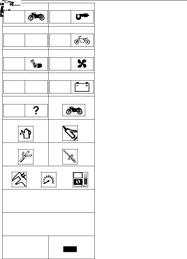
Symbols to indicate the subject of each chapter.
General informationSpecifications
Periodic checks and adjustmentsChassis
Engine
Cooling system
Carburetor(s) Electrical system
Troubleshooting
Symbols 10 to 17 indicate the following.
10 Serviceable with engine mounted11 Filling fluid
12 Lubricant13 Special tool
14 Tightening torque15 Wear limit, clearance16 Engine speed
17 Electrical data
Symbols 18 to 23 in the exploded diagrams indicate the types of lubricants and lubrication points.
18 Engine oil19 Gear oil
20 Molybdenum-disulfide oil21 Wheel-bearing grease
22 Lithium-soap- based grease23 Molybdenum-disulfide grease
Symbols 24 to 25 in the exploded diagrams indicate the following.
24 Apply locking agent (LOCTITE®)25 Replace the part

EAS00010
TABLE OF CONTENTS
GENERAL INFORMATION
GEN INFO
1 |
SPECIFICATIONS |
SPEC |
2 |
|
||
PERIODIC CHECKS AND |
|
3 |
ADJUSTMENTS |
CHK |
|
ADJ |
||
CHASSIS |
CHAS |
4 |
|
||
ENGINE |
ENG |
5 |
|
||
COOLING SYSTEM |
COOL |
6 |
|
||
CARBURETOR |
CARB |
7 |
|
||
ELECTRICAL SYSTEM |
ELEC |
8 |
|
TROUBLESHOOTING
TRBL SHTG
9 |

GEN
INFO
CHAPTER 1
GENERAL INFORMATION
MOTORCYCLE IDENTIFICATION ……………………………………………1-1 FRAME SERIAL NUMBER ……………………………………………………1-1 ENGINE SERIAL NUMBER……………………………………………………1-1
IMPORTANT INFORMATION …………………………………………………1-2 PREPARATION FOR REMOVAL ……………………………………………1-2 ALL REPLACEMENT PARTS …………………………………………………1-2 GASKETS, OIL SEALS AND O-RINGS ……………………………………1-2 LOCK WASHERS/PLATES AND COTTER PINS……………………………1-2 BEARINGS AND OIL SEALS …………………………………………………1-3 CIRCLIP …………………………………………………………………………1-3 CHECKING THE CONNECTIONS……………………………………………1-4
SPECIAL TOOLS …………………………………………………………………1-5

MOTORCYCLE IDENTIFICATIONS |
|
|
GEN |
|
|||
|
INFO |
|
|||||
|
|
EAS00014 |
|
|
|||
|
|
|
|||||
|
|
GENERAL INFORMATION |
|||||
|
|
MOTORCYCLE IDENTIFICATION |
|||||
|
|
FRAME SERIAL NUMBER |
|
|
|||
|
|
The frame IDENTIFICATION number is |
|||||
|
|
stamped onto the steering head pipe. |
|||||
|
|
NOTE: |
|
|
|
||
|
|
The frame serial number is used to identify the |
|||||
|
|
motorcycle and therefore it can be used for the |
|||||
|
|
enrollment in the face of the competent autho- |
|||||
|
|||||||
|
|
rity. |
|
|
|||
|
|
|
|
|
|
|
|
|
ENGINE SERIAL NUMBER
The engine serial number is stamped onto the left side of the crankcase.
NOTE:
The first three digits of this number identifies “the model; the other digits indicate the number” of production of the unit.
NOTE:
Design and specifications may change without notice.
1-1 |
IMPORTANT INFORMATION |
|
GEN |
|
INFO |
|
IMPORTANT INFORMATION
PREPARATION FOR REMOVAL AND
DISASSEMBLY
1.Before removal and disassembly, remove all dirt, mud, dust and foreign material.
2.Use only the proper tools and cleaning equipment.
Refer to the “SPECIAL TOOLS”.
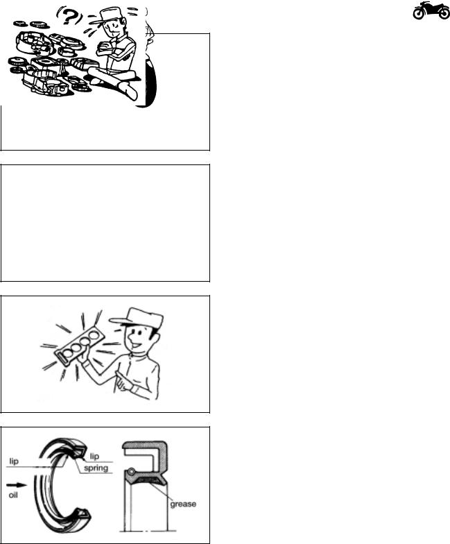
3.When disassembling, always keep mated parts together. This includes gears, cylinders, pistons and other parts that have been “mated” through normal wear. Mated parts must always be reused or replaced as an assembly.
4.During disassembly, clean all of the parts and place them in trays in the order of disassembly. This will speed up assembly and allow for the correct installation of all parts.
5.Keep all parts away from any source of fire.
EAS00021
REPLACEMENT PARTS
Use only genuine Yamaha parts for all replacements. Use oil and grease recommended by Yamaha for all lubrication jobs. Other brands may be similar in function and appearance, but inferior in quality.
EAS00022
GASKETS, OIL SEALS AND O-RINGS
1.When overhauling the engine, replace all gaskets, seals and O-rings. All gasket surfaces, oil seal lips and O-rings must be cleaned.
2.During reassembly, properly oil all mating parts and bearings and lubricate the oil seal lips with grease.
1-2
IMPORTANT INFORMATION |
|
GEN |
|
INFO |
|
EAS00024
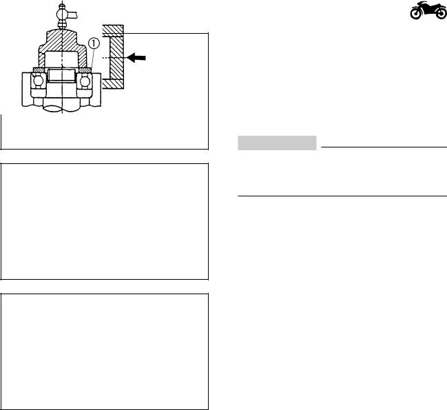
BEARINGS AND OIL SEALS
Install bearings and oil seals so that the manufacturer’s marks or numbers are visible. When installing oil seals, lubricate the oil seal lips with a light coat of lithium-soap-based grease. Oil bearings liberally when installing, if appropriate.
Oil seal
CAUTION
Do not spin the bearing with compressed air because this will damage the bearing surfaces.
Bearing
EAS00025
CIRCLIPS
Before reassembly, check all circlips carefully and replace damaged or distorted circlips. Always replace piston pin clips after one use. When installing a circlip , make sure the sharp-edged corner is positioned opposite the thrust that the circlip receives.
Shaft
1-3
CHECKING THE CONNECTIONS |
|
GEN |
|
INFO |
|
EAS00026
CHECKING THE CONNECTIONS
Check the leads, couplers, and connectors for stains, rust, moisture, etc.
1.Disconnect:
•lead
•coupler
•connector
2.Check:
•lead
•coupler
•connector
Moisture Dry with an air blower. Rust/stains Connect and disconnect several times.
3.Check:
•all connections
Loose connection Connect properly.
NOTE:
If the pin on the terminal is flattened, bend it up.
4.Connect:
•lead
•coupler
•connector
NOTE:
Make sure all connections are tight.
5.Check:
•continuity
(with the pocket tester)
Pocket tester 90890-03112, YU-3112
NOTE:
•If there is no continuity, clean the terminals.
•When checking the wire harness, perform steps (1) to (3).
•As a quick remedy, use a contact revitalizer available at most part stores.
1-4

SPECIAL TOOLS |
|
GEN |
|
INFO |
|
EAS00027
SPECIAL TOOLS
The following special tools are necessary for complete and accurate tune-up and assembly. Use only the appropriate special tools as this will help prevent damage caused by the use of inappropriate tools or improvised techniques. Special tools, part numbers or both may differ depending on the country.
When placing an order, refer to the list provided below to avoid any mistakes.
Tool No. |
Tool name / Usage |
|
|
|
|
|
Illustration |
||||
|
|
|
|
|
|
|
|
|
|
|
|
90890-01312 |
Fuel level gauge |
|
|
|
|
|
|
|
|
|
|
|
|
|
|
|
|
|
|
|
|
||
|
This gauge is used to measure the fuel level in |
|
|
|
|
|
|
|
|
|
|
|
the float chamber. |
|
|
|
|
|
|
|
|
|
|
|
|
|
|
|
|
|
|
|
|
|
|
90890-03113 |
Engine tachometer |
|
|
|
|
|
|
|
|
|
|
|
|
|
|
|
|
|
|
|
|
||
|
This tool is needed for detecting engine rpm. |
|
|
|
|
|
|
|
|
|
|
|
|
|
|
|
|
|
|
|
|
|
|
90890-04086 |
Universal tool of subjection of the clutch |
|
|
|
|
|
|
|
|
|
|
|
|
|
|
|
|
|
|
|
|
||
|
This tool is used to immobilize the clutch |
|
|
|
|
|
|
|
|
|
|
|
during the assembly or disassembly of the |
|
|
|
|
|
|
|
|
|
|
|
blockade nut of the clutch. |
|
|
|
|
|
|
|
|
|
|
|
|
|
|
|
|
|
|
|
|
|
|
|
|
|
|
|
|
|
|
|
|
|
|
90890-01701 |
Sheave holder |
|
|
|
|
|
|
|
|
|
|
|
|
|
|
|
|
|
|
|
|
||
|
This tool is used for holding the secondary |
|
|
|
|
|
|
|
|
|
|
|
sheave. |
|
|
|
|
|
|
|
|
|
|
|
|
|
|
|
|
|
|
|
|
|
|
|
|
|
|
|
|
|
|
|
|
|
|
90890-01362 |
Flywheel puller |
|
|
|
|
|
|
|
|
|
|
|
|
|
|
|
|
|
|
|
|
||
|
For removing the flywheel. |
|
|
|
|
|
|
|
|
|
|
|
|
|
|
|
|
|
|
|
|
|
|
90890-01304 |
Piston pin puller |
|
|
|
|
|
|
|
|
|
|
|
|
|
|
|
|
|
|
|
|
||
|
This tool is used to remove the piston pin. |
|
|
|
|
|
|
|
|
|
|
|
|
|
|
|
|
|
|
|
|
|
|
|
|
|
|
|
|
|
|
|
|
|
|
90890-01325 |
Radiator cap tester |
|
|
|
|
|
|
|
|
|
|
|
|
|
|
|
|
|
|
|
|
||
90890-01352 |
Adaptor |
|
|
|
|
|
|
|
|
|
|
|
These tools are used for checking the |
|
|
|
|
|
|
|
|
|
|
|
|
|
|
|
|
|
|
|
|
|
|
|
|
|
|
|
|
|
|
|
|
|
|
|
cooling system. |
|
|
|
|
|
|
|
|
|
|
|
|
|
|
|
|
|
|
|
|
|
|
|
|
|
|
|
|
|
|
|
|
|
|
1-5
|
SPECIAL TOOLS |
|
GEN |
|
|
||
|
INFO |
|
|
||||
|
|
|
|
|
|
||
Tool No. |
Tool name / Usage |
|
|
Illustration |
|||
|
|
|
|
|
|
|
|
90890-01135 |
Crankcase separation tool |
|
|
|
|
|
|
|
|
|
|
|
|
||
|
This tool is used to remove the crankshaft |
|
|
|
|
|
|
|
or separate the crankcase. |
|
|
|
|
|
|
|
|
|
|
|
|
|
|
|
|
|
|
|
|
|
|
90890-01274 (1) |
Cranckshaft intalling tool |
|
|
|
|
|
|
|
|
|
|
|
|
||
-01275 (2) |
Crankshaft pin |
|
|
|
|
|
|
-01278 (3) |
Adapter(M12) |
|
|
|
|
|
|
|
|
|
|
|
|
|
|
|
|
|
|
|
|
|
|
|
|
|
|
|
|
|
|
|
|
|
|
|
|
|
|
|
|
|
|
|
|
|
|
90890-01326 |
T-Handle |
|
|
|
|
|
|
|
|
|
|
|
|
||
|
This tool is used for holding the damper |
|
|
|
|
|
|
|
rod holder when removing or installing |
|
|
|
|
|
|
|
the damper rod holder. |
|
|
|
|
|
|
|
|
|
|
|
|
|
|
|
|
|
|
|
|
|
|
90890-01367 |
Fork seal driver weight |
|
|
|
|
|
|
-01381 |
Fork seal driver attachment |
|
|
|
|
|
|
|
This tool is used when installing the fork seal. |
|
|
|
|
|
|
|
|
|
|
|
|
|
|
|
|
|
|
|
|
|
|
|
|
|
|
|
|
|
|
|
|
|
|
|
|
|
|
90890-01403 |
Ring nut wrench |
|
|
|
|
|
|
|
|
|
|
|
|
||
|
This tool is used to loosen and tighten |
|
|
|
|
|
|
|
the steering ring nut. |
|
|
|
|
|
|
|
|
|
|
|
|
|
|
|
|
|
|
|
|
|
|
90890-03112 |
Pocket tester |
|
|
|
|
|
|
|
|
|
|
|
|
||
|
These instruments are invaluable for |
|
|
|
|
|
|
|
checking the electrical system. |
|
|
|
|
|
|
|
|
|
|
|
|
|
|
|
|
|
|
|
|
|
|
1-6

SPEC
CHAPTER 2
SPECIFICATIONS
GENERAL SPECIFICATIONS …………………………………………………2-1 ENGINE SPECIFICATIONS……………………………………………………2-4 CHASSIS SPECIFICATIONS …………………………………………………2-6 ELECTRICAL SPECIFICATIONS ……………………………………………2-8
CONVERSION TABLE …………………………………………………………2-10
GENERAL TIGHTENING TORQUE SPECIFICATIONS ……………………2-10 ENGINE ………………………………………………………………………2-11 CHASSIS ……………………………………………………………………2-11
COOLANT FLOW CHART ……………………………………………………2-13
LUBRICATION POINTS AND LUBRICANT TYPE …………………………2-14 ENGINE ………………………………………………………………………2-14 CHASSIS ………………………………………………………………………2-15
CABLE ROUTING ………………………………………………………………2-16

GENERAL SPECIFICATIONS |
SPEC |
|
|
|
|
||
|
|
|
|
SPECIFICATIONS |
|
|
|
GENERAL SPECIFICATIONS |
|
|
|
Model |
DT125RE |
|
DT125X |
Model code |
1D01/1D02 |
|
2C81 |
Dimensions: |
|
|
|
Overall lenght |
2210mm |
|
2139mm |
Overall width |
795mm |
|
1121mm |
Overall height |
1200mm |
|
1200mm |
Seatheight |
900mm |
|
886mm |
Wheelbase |
1415mm |
|
1396mm |
Minimum ground clearance |
300mm |
|
271 mm |
Minimum turning radius |
2100mm |
|
2016mm |
Basic weight: |
|
|
|
With oil and full fuel tank |
126kg |
|
134 kg |
Engine: |
|
|
|
Engine type: |
2 strokes, liquid cooled |
||
Induction system |
Reed valve |
|
|
Cylinder arrangement |
Forward-inclined single cylinder |
||
Displacement |
124cm3 |
|
|
BorexStroke |
56,0x50,7 |
|
|
Compression ratio |
6,7:1 |
|
|
Maximum power |
11kW /8000rpm |
|
|
Maximum torque |
13Nm/8000rpm |
|
|
Idle speed |
1250~1450r/min |
|
|
Starting system |
Electric starter |
|
|
Lubrication system |
Yamaha Autolube |
|
|
Oil type or grade: |
|
|
|
Engine oil |
2T motor oil (JASO grade FC) |
||
Total amount |
1,3L |
|
|
Transmission oil |
Type SE motor oil |
|
|
Periodic oil change |
0,75L (0,79 us. qt.) |
|
|
Total amount |
0,8L (0,85 us.qt.) |
|
|
Radiator capacity: |
|
|
|
Total amount (including all routes) |
0,92L |
|
|
Coolant reservoir capacity |
0,30L |
|
|
Air filter: |
Wet type element |
|
|
Fuel |
|
|
|
Type |
Regular unleaded gasoline |
||
Fuel tank capacity: |
10,7L |
|
|
Reserve |
1,8L |
|
|
Carburetor: |
|
|
|
Type/quantity |
TM28-92 / 1 |
|
|
Manufacturer: |
MIKUNI |
|
|
|
|
|
|
2-1

GENERAL SPECIFICATIONS |
SPEC |
|
|
|
|
||
|
|
|
|
Model code |
|
1D01/1D02 |
|
2C81 |
Spark plug: |
|
|
|
|
Type |
|
BR8ES |
|
|
Manufacturer |
NGK |
|
||
Spark plug gap |
0,7~0,8mm (0,0276~0,03315in) |
|||
Clutch type |
|
Wet, multiple disc |
|
|
Transmission: |
|
|
|
|
Primary reduction system |
Helical gear |
|
||
Primary reduction ratio |
71/22(3,227) |
|
|
|
Secondary reduction system |
chain drive |
|
||
Secondary reduction ratio |
57/16(3,563) |
|
|
|
Transmission type |
Constant mesh, 6 speed |
|||
Operation |
|
Left foot operation |
|
|
Gear ratio: |
|
|
|
|
1ª |
|
34/12(2.833) |
|
|
2ª |
|
30/16(1.875) |
|
|
3ª |
|
24/17(1.412) |
|
|
4ª |
|
24/21(1.143) |
|
|
5ª |
|
22/23(0.957) |
|
|
6ª |
|
18/22(0.818) |
|
|
Chassis: |
|
|
|
|
Frame type: |
Semi double cradle |
|
Semi double cradle |
|
Castor angle |
27º |
|
24,5° |
|
Trail |
|
107mm |
|
73,1 mm |
Tire: |
|
|
|
|
Type |
|
With tube |
|
With tube |
Size |
Front |
80/90-21 48P |
|
120/70-17 58H |
|
|
|||
|
Rear |
110/80-18 58P |
|
140/70-17 66H |
Manufacturer |
Michelin /T63 |
|
Pirelli/ Sport Demon |
|
Cold tire pressure: |
150kPa (1.5kgf/cm2) |
|
180kPa (1.8kgf/cm2) |
|
Front |
0~90kg |
|
||
Rear |
0~90kg |
175kPa (1.75kgf/cm2) |
|
200kPa (2.0kgf/cm2) |
Front |
90~178kg |
175kPa (1.75kgf/cm2) |
|
180kPa (1.8kgf/cm2) |
Rear |
90~178kg |
200kPa (2.0kgf/cm2) |
|
200kPa (2.0kgf/cm2) |
Off road riding: |
150kPa (1.5kgf/cm2) |
|||
Front |
|
|||
Rear |
|
175kPa(1.75kgf/cm2) |
||
Brakes: |
|
|
|
|
Front brake type |
Single disc brake |
|
Single disc brake |
|
|
|
230mm diameter |
|
298 mm diameter |
Front brake operation |
Right hand operation |
|
Right hand operation |
|
Rear brake type |
Single disc brake |
|
Single disc brake |
|
|
|
220mm diameter |
|
220 mm diameter |
Rear brake operation |
Right foot operation |
|
Right foot operation |
|
Suspensions: |
|
|
|
|
Front |
|
Telescopic fork |
|
|
Rear |
|
Swingarm (monocross suspension) |
||
Shock absorber: |
|
|
|
|
Front |
|
Coil-air spring/Oil damper |
||
Rear |
|
Coil and gas spring/Oil damper |
||
|
|
|
|
|
2-2

GENERAL SPECIFICATIONS |
SPEC |
|
|
|
|
||
|
|
|
|
Model code |
1D01/1D02 |
2C81 |
Wheel travel: |
|
|
Front wheel travel |
270mm(10.63in) |
200mm (7,87in) |
Rear wheel travel |
260mm(10.24in) |
230mm (9.05in) |
Electrical: |
|
|
Ignition system |
CDI |
|
Charging system |
AC Magneto |
|
Battery type |
GT6B-3 |
|
Capacity |
12V 6Ah |
|
Headlight: |
bulb type |
|
Bulb wattage x quantity: |
|
|
Headlight |
12V60W/55W x 1 |
|
Tail/Brake light |
12V21W/5W x 1 |
|
Turn signal indicator light |
|
|
Front |
12V10W x 1 |
|
Rear |
12V10W x 1 |
|
Meter |
LED |
|
Control lights: |
|
|
“OIL” |
12V3W X 1 |
|
“TURN” |
12V3W X 1 |
|
“NEUTRAL” |
12V3W X 1 |
|
“HIGH BEAM” |
12V3W X 1 |
|
“LOW BEAM” |
12V3W X 1 |
|
Amperages: |
|
|
Principal fuse |
15A |
|
|
|
|
2-3
GENERAL SPECIFICATIONS |
SPEC |
|
|
|
|
||
|
|
|
|
ENGINE
Item |
Standard |
Limit |
||||||
|
|
|
|
|
|
|
|
|
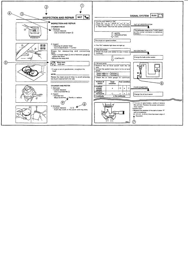
Cylinder head: |
|
|
|
|
|
|
|
|
|
|
|
|
|
||||
Warpage limit |
|
|
|
|
|
|
* Lines indicate |
0,03mm |
|
|
|
|
|
|
|
straightedge |
|
|
|
|
|
|
|
|
measurement. |
|
|
|
|
|
|
|
|
|
|
|
|
|
|
|
|
|
|
|
Cylinder: |
|
|
||||||
Bore size |
56.00~56.02mm |
*** |
||||||
Taper limit |
0.05mm |
*** |
||||||
Out of round limit |
0.01mm |
*** |
||||||
|
|
|
|
|
|
|
|
|
Piston: |
|
|
|
|
|
|
||
|
|
|
|
|
||||
Piston size “D” |
|
|
|
|
55.950~55.955 |
*** |
||
Measurement point* |
|
|
|
|
10mm |
*** |
||
Piston to cylinder |
|
|
|
|
|
|
||
clearance |
|
|
|
|
0.045~0.050mm |
0.10mm |
||
Piston Offset |
|
|
|
|
0.5mm |
*** |
||
|
|
|
|
|
|
|
|
|
|
|
|
|
|
|
|
|
|
Piston ring: |
|
|
|
|
||||
|
|
|
||||||
Type |
|
|
Keystone |
*** |
||||
Dimensions(BxT): |
|
|
* |
* |
||||
Top ring |
|
|
1.2x2.4mm |
*** |
||||
2nd ring |
|
|
1.20x1.89mm |
*** |
||||
|
||||||||
End gap (installed): |
* |
* |
||||||
Top ring |
0.30~0.45mm |
*** |
||||||
2nd ring |
0.30~0.45mm |
*** |
||||||
Side clearance: |
* |
* |
||||||
Top ring |
0.02~0.06mm |
*** |
||||||
2nd ring |
0.035~0.070mm |
*** |
||||||
|
|
|
|
|
|
|
|
|
Cooling system: |
|
|
||||||
Radiator capacity (including all routes) |
0.92L |
*** |
||||||
Reservoir tank capacity |
0.3L |
* |
||||||
Radiator cap opening pressure |
75~105kPa |
*** |
||||||
|
|
|
|
|
|
|
(0.75~1.05kgf/cm2) |
|
Radiator core width |
110mm |
*** |
||||||
Radiator core height |
280mm |
*** |
||||||
Radiator core thickness |
32mm |
*** |
||||||
Water pump type |
Single-suction centrifugal |
|
||||||
|
|
|
|
|
|
|
pump |
|
|
|
|
|
|
|
|
|
|
2-4

GENERAL SPECIFICATIONS |
SPEC |
|
|
|
|
||
|
|
|
|
Item |
Standard |
Limit |
||
|
|
|
|
|
Crankshaft: |
|
|
|
|
Crank width “A” |
|
|
57.90~57.95mm |
*** |
Runout limit “C” |
|
|
*** |
0.03mm |
Big end side clearance |
“D” |
|
0.2~0.7mm |
*** |
Small end free play “E” |
|
|
0.026~0.040mm |
*** |
|
|
|
|
|
Clutch: |
|
|
||
Friction plate thickness |
2.9~3.1mm |
2.7mm |
||
Quantity |
7pcs |
*** |
||
Clutch plate thickness |
1.05~1.35mm |
0.05mm |
||
Quantity |
6pcs |
*** |
||
Clutch spring Free lenght |
34.5mm |
*** |
||
Quantity |
5pcs |
*** |
||
Minimum free lenght |
32mm |
*** |
||
Push rod bending limit |
0.15mm |
*** |
||
Transmission: |
|
|
||
Main axle runout limit |
*** |
0.08mm |
||
Drive axle runout limit |
*** |
0.08mm |
||
Carburetor: |
|
|
||
Type |
TM28-92/1 |
*** |
||
ID Mark |
1DO |
*** |
||
Main jet |
#210 |
*** |
||
Air jet |
0.7 |
*** |
||
Jet Needle position |
5J40-2 |
*** |
||
Needle jet |
Q2M (#939) |
*** |
||
Pilot outlet |
0.6 |
*** |
||
Pilot jet |
#17.5 |
*** |
||
Bypass1 |
1.6 |
*** |
||
Air screw turns |
1/4 |
*** |
||
Valve seat size |
2.8 |
*** |
||
Starter jet 1 |
#40 |
*** |
||
Power jet |
#60 |
*** |
||
Float height |
15.5~16.5mm |
*** |
||
Fuel level |
1.5~2.5mm |
|
||
Idling speed |
1250~1450r.p.m |
|
||
Air filter: |
|
|
||
Type |
Wet element |
*** |
||
Oil type/grade |
Foam air filter oil or |
*** |
||
|
|
|
SAE10W30SE |
|
Reed valve: |
|
|
||
Valve thickness |
0.5mm |
*** |
||
Valve stopper height |
8.8mm |
*** |
||
Valve bending limit |
0.5mm |
*** |
||
Lubrication system: |
|
|
||
Autolube pump |
* |
* |
||
Color code |
Dark blue |
*** |
||
Minimum stroke |
0.15~0.20mm |
*** |
||
Maximum stroke |
1.85~2.05mm |
*** |
||
Minimum output |
0.38~0.50cm3 |
*** |
||
Maximum output |
4.65~5.15cm3 |
*** |
||
Pulley adjusting mark |
autoadjustable |
*** |
||
|
|
|
|
|
2-5
GENERAL SPECIFICATIONS |
SPEC |
|
|
|
|
||
|
|
|
|
CHASSIS |
|
|
|
Item |
Standard |
Limit |
||
Model code |
1D0 |
2C81 |
1D0 |
2C81 |
Front wheel: |
|
|
|
|
Type |
Spoke wheels |
Spoke wheels |
|
|
Rim Size |
21x1.60 |
17 x 3.00 |
|
|
Rim Material |
Steel |
Steel |
|
|
Front wheel travel: |
270mm |
270mm |
|
|
Max. Radial wheel runout |
1mm |
1mm |
|
|
Max. Lateral wheel runout |
0.5mm |
0.5mm |
|
|
|
|
|
|
|
Rear wheel: |
|
|
|
|
Type |
Spoke wheels |
Spoke wheels |
|
|
Rim size |
18x1.85 |
17x3.50 |
|
|
Rim material |
Steel |
Steel |
|
|
Rear wheel travel |
260mm(10.24in) |
260mm(10.24in) |
|
|
Max. Radial wheel runout |
1mm(0.04in) |
1mm(0.04in) |
|
|
Max. Lateral wheel runout |
0.5mm(0.02in) |
0.5mm(0.02in) |
|
|
|
|
|
|
|
Front disc brake: |
|
|
|
|
Thickness |
230.0x3.5mm |
230.0x3.5mm |
|
|
Brake pad lining thickness-inner |
6mm |
4.1mm |
0.8mm |
0.5mm |
Brake pad lining thickness-outer |
6 mm |
6 mm |
0.8mm |
0.8mm |
Master cylinder inside diameter |
11mm |
11mm |
|
|
Caliper cylinder inside diameter |
34.93mm |
34.93mm |
|
|
Recommended fluid |
DOT 4 |
DOT 4 |
|
|
|
|
|
|
|
Rear disc brake: |
|
|
|
|
Thickness |
220.0x4.5mm |
|
|
|
Brake pad lining thickness-inner |
5.6mm |
1.0mm |
||
Brake pad lining thickness-outer |
5.6mm |
1.0mm |
||
Master cylinder inside diameter |
12.7mm |
|
|
|
Caliper cylinder inside diameter |
30.16mm |
|
|
|
Recommended fluid |
DOT 4 |
|
|
|
|
|
|
|
|
Steering system: |
|
|
|
|
Steering type |
Ball and taper roller |
|
|
|
Bearing size (quantity) |
bearing |
|
|
|
|
|
|
|
|
Upper |
22pcs (0.1875in) |
|
|
|
|
|
|
|
|
Front suspension: |
|
|
|
|
Front fork travel |
270mm |
200 mm |
|
|
Fork free lenght |
503mm |
503mm |
|
|
Spring rate K1 |
3.1N/mm |
3.1N/mm |
|
|
Spring stroke K1 |
0~270mm |
0~270mm |
|
|
Optional spring available |
No |
No |
|
|
Recommended oil |
Fork oil 10W |
Fork oil 10W |
|
|
Quantity |
495cm3 |
495cm3 |
|
|
Level |
165.5mm |
165.5mm |
|
|
|
|
|
|
|
2-6

GENERAL SPECIFICATIONS |
SPEC |
|
|
|
|
||
|
|
|
|
Item |
Standard |
Limit |
||
Model code |
1D0 |
2C81 |
1D0 |
2C81 |
Rear suspension: |
|
|
|
|
Type |
Swingarm |
Swingarm |
|
|
|
(link suspension) |
(link suspension) |
|
|
Rear shock absorber assemby travel |
93mm |
87 mm |
|
|
Spring free lenght |
245mm |
250mm |
|
|
Installed lenght |
230mm |
244mm |
|
|
Spring preload (spring lenght) |
Hard/Soft |
Hard/Soft |
|
|
|
(220/235mm) |
(234/249mm) |
|
|
Spring rate K1 |
68.6N/mm |
117.80N/mm |
|
|
Spring stroke K1 |
0~93mm |
0~87mm |
|
|
Optional spring available |
No |
No |
|
|
Enclosed gas/air pressure (STD) |
150kPa |
150kPa |
|
|
|
(15kgf/cm2) |
(15kgf/cm2) |
|
|
Tightening torque spring preload |
20~25Nm |
20~25Nm |
|
|
|
|
|
|
|
Drive chain: |
|
|
|
|
Type/Manufacturer |
428V2/DAIDO |
428V2/DAIDO |
|
|
Link quantity |
134 |
134 |
|
|
Drive chain slack |
45~55mm |
25~40mm |
|
|
|
(1.77~2.16in) |
(0.98~1.57in) |
|
|
|
|
|
|
|
Front lever brake/Rear brake pedal: |
|
|
|
|
Free play front lever brake |
2~5mm |
|
|
|
Brake pedal free play |
15mm |
|
|
|
|
|
|
|
|
2-7

|
GENERAL SPECIFICATIONS |
|
GEN |
|
|||
|
|
INFO |
|
||||
ELECTRICAL |
|
|
|
|
|
|
|
|
|
|
|
|
|||
Model |
|
1D01/1D02 |
|
2C81 |
|||
System voltage |
|
12 V |
|
|
|||
|
|
|
|
|
|
|
|
Ignition system: |
|
|
|
|
|
|
|
Ignition system type |
|
C.D.I. |
|
|
|||
Ignition timing (B.T.D.C.) ((º)) |
|
17 /1500r/min |
|
|
|||
Advancer type |
|
Digital |
|
|
|||
|
|
|
|
|
|
|
|
C.D.I.: |
|
|
|
|
|
|
|
Magneto model/manufacturer |
|
F4FU/YAMAHA |
|
|
|||
Pick up coil resistance((ohm)) |
|
310±20%W/R-W/L |
|
|
|||
Source coil resistance ((ohm)) |
|
730±20%B/R-G/W |
|
|
|||
Source coil resistance ((ohm)) |
|
600±20%G/L-G/W |
|
|
|||
CDI unit model/manufacturer |
|
1D0 /YAMAHA |
|
|
|||
|
|
|
|
|
|
|
|
Ignition coil: |
|
|
|
|
|
|
|
Model/Manufacturer |
|
3RW/YAMAHA |
|
|
|||
Primary coil resistance ((ohm)) |
|
0.23±20% |
|
|
|
|
|
Secondary coil resistance ((ohm)) |
|
7.9±20% |
|
|
|
|
|
|
|
|
|
|
|
|
|
Spark plug cap: |
|
|
|
|
|
|
|
Material |
|
Resin |
|
|
|||
Resistance ((k ohm)) |
|
5 |
|
|
|
|
|
|
|
|
|
|
|
|
|
A.C. Magneto: |
|
|
|
|
|
|
|
Model/Manufacturer |
|
F4FU/YAMAHA |
|
|
|||
Standard output |
|
14V170W5000r/min |
|
|
|||
Coil resistance ((ohm)) |
|
0.6±20%W-W |
|
|
|||
|
|
|
|
|
|
|
|
Regulator: |
|
|
|
|
|
|
|
Regulator type |
|
Semi conductor-short circuit |
|||||
Model/Manufacturer |
|
SH629B-11/SHINDENGEN |
|||||
No load regulated voltage |
|
14.1~14.9V |
|
|
|||
|
|
|
|
|
|
|
|
Rectifier: |
|
|
|
|
|
|
|
Rectifier capacity |
|
25A |
|
|
|||
Withstand voltage |
|
200V |
|
|
|||
|
|
|
|
|
|
|
|
Battery: |
|
|
|
|
|
|
|
Battery type |
|
GT6B-3 |
|
|
|||
Battery voltage/Capacity |
|
12V6Ah |
|
|
|||
|
|
|
|
|
|||
Bulbs (voltage/wattage x quantity) |
|
|
|
|
|||
Headlight type |
|
Bulb type |
|
|
|||
Headlight bulb type |
|
Halogen H4 |
|
|
|||
Headlight |
|
12V60W/55Wx1 |
|
|
|||
Auxiliary light |
|
12V5Wx1 |
|
|
|||
Brake/tail light |
|
12V21W/5Wx1 |
|
|
|||
Front flasher light |
|
12V10Wx2 |
|
|
|||
Rear flasher light |
|
12V10Wx2 |
|
|
|||
Meter light |
|
LED |
|
|
|||
|
|
|
|
|
|
|
|
2-8

|
GENERAL SPECIFICATIONS |
|
GEN |
|
||
|
|
INFO |
|
|||
|
|
|
|
|
|
|
Indicator light |
|
|
|
|
|
|
Neutral indicator light |
|
12V3Wx1 |
|
|
||
Turn indicator light |
|
12V3Wx1 |
|
|
||
Oil level indicator light |
|
12V3Wx1 |
|
|
||
High beam indicator light |
|
12V3Wx1 |
|
|
||
|
|
|
|
|
|
|
Starting system: |
|
|
|
|
|
|
System type |
|
Electric starter |
|
|
||
|
|
|
|
|
|
|
Starter motor: |
|
|
|
|
|
|
Model/Manufacturer |
|
3MB / Moric |
|
|
||
Power output |
|
0.2kW |
|
|
||
Armature coil resistance |
|
0.0315~0.0385<ohm> 20ºC |
||||
Brush overal lenght |
|
5X7X7 |
|
|
||
<Limit> |
|
3,5 |
|
|
|
|
Brush spring force |
|
4.9N ±20% |
|
|
||
<Limit> |
|
3.92N |
|
|
||
Commutator diameter |
|
17.6mm |
|
|
||
<Limit> |
|
16.6mm |
|
|
||
Mica undercut (depth) |
|
1.35mm |
|
|
||
|
|
|
|
|
|
|
Starter relay: |
|
|
|
|
|
|
Model/Manufacturer |
|
1D0/JIDECO |
|
|
||
Amperage |
|
180A |
|
|
||
Coil resistance |
|
4.2 - 4.6<ohm> 20ºC |
||||
|
|
|
|
|
|
|
Horn: |
|
|
|
|
|
|
Horn type |
|
Plane |
|
|
||
Quantity |
|
1 |
|
|
|
|
Model/Manufacturer |
|
YF-12/NIKKO |
|
|
||
Max. Amperage |
|
3A |
|
|
||
Performance |
|
105~113db/2m |
|
|
||
|
|
|
|
|
|
|
Turn signal relay: |
|
|
|
|
|
|
Relay type |
|
Full transistor |
|
|
||
Model/Manufacturer |
|
FE218BH/DENSO |
|
|
||
Turn signal blinking frequency |
|
75~95cyl/min |
|
|
||
Wattage |
|
10Wx2+3.4W |
|
|
||
|
|
|
|
|
|
|
Oil level gauge: |
|
|
|
|
|
|
Model/Manufacturer |
|
3XP/ASTI |
|
|
||
|
|
|
|
|
|
|
Starting citcuit cutt-off relay: |
|
|
|
|
|
|
Model/Manufacturer |
|
25G/OMRON |
|
|
||
Coil resistance |
|
100<ohm>±10% |
|
|
||
|
|
|
|
|
|
|
Headlight relay: |
|
|
|
|
|
|
Model/Manufacturer |
|
25G/OMRON |
|
|
||
Coil resistance |
|
100<ohm>±10% |
|
|
||
|
|
|
||||
Side stand relay: |
|
BUILT IN CUT OFF RELAY |
||||
|
|
|
|
|
|
|
Thermostat switch: |
|
|
|
|
|
|
Model/Manufacturer |
|
4BA/DENSO |
|
|
||
Temperature setting |
|
120±3<degree> |
|
|
||
|
|
|
|
|
|
|
Servo motor: |
|
|
|
|
|
|
Model/Manufacturer |
|
3XP/MATSUSHITA |
|
|
||
|
|
|
|
|
|
|
Amperage for fuses: |
|
|
|
|
|
|
Main fuse |
|
15A |
|
|
||
Spare fuse |
|
15A |
|
|
||
|
|
|
|
|
|
|
2-9
CONVERSION TABLE / |
SPEC |
|
|
GENERAL TIGHTENING TORQUES SPECIFICATIONS |
|
||
|
|
||
|
|
|
|
EAS00028 EAS00029
CONVERSION TABLE
All specification data in this manual are listed in SI and METRIC UNITS.
Use this table to convert METRIC unit data to IMPERIAL unit data.
Ex. |
|
|
|
|
|
|
METRIC |
MULTIPLIER |
|
IMPERIAL |
|||
** mm |
x |
0.03937 |
= |
** in |
||
2 mm |
x |
0.03937 |
= |
0.08 in |
||
|
|
CONVERSION TABLE |
||||
|
|
|
|
|||
|
METRIC TO IMPERIAL |
|||||
|
Metric unit |
Multiplier |
Imperial unit |
|||
|
|
m•kg |
7.233 |
|
ft•lb |
|
Tightening |
|
m•kg |
86.794 |
|
in•lb |
|
Torque |
|
cm•kg |
0.0723 |
|
ft•lb |
|
|
|
cm•kg |
0.8679 |
|
in•lb |
|
|
|
|
|
|
|
|
Weight |
|
kg |
2.205 |
|
lb |
|
|
|
|
g |
0.03527 |
oz |
|
|
|
|
|
|
|
|
Speed |
|
km/hr |
0.6214 |
|
mph |
|
|
|
|
|
|
|
|
|
|
km |
0.6214 |
|
mi |
|
|
|
m |
3.281 |
|
ft |
|
Distance |
|
m |
1.094 |
|
yd |
|
|
|
cm |
0.3937 |
|
in |
|
|
|
mm |
0.03937 |
in |
||
|
|
|
|
|
||
|
|
cc (cm3) |
0.03527 |
oz (IMP liq.) |
||
Volume, |
|
cc (cm3) |
0.06102 |
cu•in |
||
Capacity |
|
lt (liter) |
0.8799 |
|
qt (IMP liq.) |
|
|
|
lt (liter) |
0.2199 |
|
gal (IMP liq.) |
|
|
|
|
|
|
|
|
|
|
kg/mm |
55.997 |
|
lb/in |
|
Misc. |
|
kg/cm2 |
14.2234 |
psi (lb/in2) |
||
|
Centigrade |
9/5 + 32 |
Fahrenheit (°F) |
|||
|
|
(°C) |
|
|
|
|
|
|
|
|
|
|
|
GENERAL TIGHTENING TORQUE SPECIFICATIONS
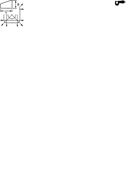
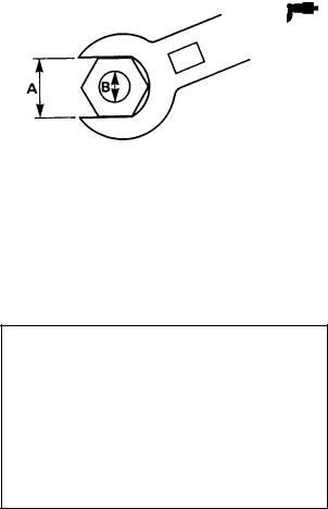
This chart specifies tightening torques for standard fasteners with a standard ISO thread pitch. Tightening torque specifications for special components or assemblies are provided for each chapter of this manual. To avoid warpage, tighten multi-fastener assemblies in a crisscross pattern and progressive stages until the specified tightening torque is reached. Unless otherwise specified, tightening torque specifications require clean, dry threads. Components should be at room temperature.
A:Width across flats
B:Thread diameter
A |
B |
General tightening |
||
torques |
||||
(nut) |
(bolt) |
|
|
|
Nm |
m • kg |
|||
|
|
|||
10 mm |
6 mm |
6 |
0.6 |
|
12 mm |
8 mm |
15 |
1.5 |
|
14 mm |
10 mm |
30 |
3.0 |
|
17 mm |
12 mm |
55 |
5.5 |
|
19 mm |
14 mm |
85 |
8.5 |
|
22 mm |
16 mm |
130 |
13.0 |
|
|
|
|
|
|
2-10

DEFINITION OF UNITS |
SPEC |
|
|
|
|
||
|
|
|
|
TIGHTENING TORQUES
ENGINE
|
|
|
|
Tightening |
|
|
|
|
|
|
|
|
Thread |
torque |
|
|
|
|
|
Part to be tightened |
|
Q’ty |
size |
Nm |
m•kg |
Remarks |
|||
|
|
|
|
|
|
|
|
|
|
Spark plug |
|
1 |
M14x1.25 |
20 |
2,0 |
|
|
|
|
Cylinder head |
Nut |
5 |
M8x1.25 |
22 |
2,2 |
|
|
|
|
Cylinder |
Stud bolt |
9 |
M8X1.25 |
13 |
1,3 |
LOCTITE |
|||
|
|
|
|
|
|
screw glue |
|||
|
Nut |
4 |
M8x1.25 |
28 |
2,8 |
|
|
|
|
|
|
|
|
|
|
|
|
|
|
Power valve holder, Valve cover |
Cap seal |
|
|
|
|
|
|
|
|
|
|
|
|
|
|
|
|
|
|
|
Bolt |
6 |
M5x0.8 |
7 |
0,7 |
|
|
|
|
Power valve pully |
Bolt |
|
M6x1.0 |
10 |
1,0 |
|
|
|
|
|
|
|
|
|
|
|
|
|
|
Thermostat valve cover |
Screw |
3 |
M6x1.0 |
8 |
0,8 |
|
|
|
|
Housing cover |
Screw |
2 |
M6x1.0 |
8 |
0,8 |
|
|
|
|
|
Drain bolt (Housing cover) |
1 |
M6x1.0 |
10 |
1 |
|
|
|
|
Radiator |
Bolt |
2 |
M6x1.0 |
8 |
0,8 |
|
|
|
|
Radiator cap stopper |
Screw |
1 |
M5x0.8 |
5 |
0,5 |
|
|
|
|
Oil pump |
Screw |
2 |
M5x0.8 |
5 |
0,5 |
|
|
|
|
Carburetor joint |
Bolt |
4 |
M6x1.0 |
8 |
0,8 |
|
|
|
|
|
|
|
|
|
|
|
|
|
|
Air filter |
Screw |
2 |
M6x1.0 |
5 |
0,5 |
|
|
|
|
Exhaust pipe |
Nut |
2 |
M8x1.25 |
18 |
1,8 |
|
|
|
|
|
Stud bolt |
2 |
M8x1.25 |
10 |
1 |
LOCTITE |
|||
|
|
|
|
|
|
screw glue |
|||
|
Bolt |
3 |
M6x1.0 |
8 |
0,8 |
|
|
|
|
|
|
|
|
|
|||||
|
|
|
|
|
|||||
|
|
|
|
|
|
|
|
|
|
Transmission Oil |
Drain Bolt |
1 |
M8x1.25 |
15 |
1,5 |
|
|
|
|
Crankcase cover (left) |
Screw |
6 |
M6x1.0 |
5 |
0,5 |
|
|
|
|
Crankcase cover (right) |
Screw |
6 |
M6x1.0 |
8 |
0,8 |
|
|
|
|
Oil pump cover |
Screw |
3 |
M6x1.0 |
5 |
0,5 |
|
|
|
|
Crankcase |
Screw |
12 |
M6x1.0 |
8 |
0,8 |
|
|
|
|
|
|
|
|
|
|
|
|
|
|
Oil Seal Holder |
Screw |
1 |
M8x1.25 |
16 |
1,6 |
|
|
|
|
Cover |
Screw |
2 |
M6x1.0 |
8 |
0,8 |
|
|
|
|
Kick Crank Bass |
Nut |
1 |
M12X1.0 |
70 |
7 |
|
|
|
|
Clutch Spring |
Bolt |
5 |
M5x0.8 |
6 |
0,6 |
|
|
|
|
|
|
|
|
|
|
|
|
|
|
Plate cover |
Screw |
2 |
M6x1.0 |
10 |
1 |
|
|
|
|
Drive Sprocket |
Nut |
1 |
M16X1.0 |
60 |
6 |
|
|
|
|
Tachometer housing |
Bolt |
1 |
M6x1.0 |
5 |
0,5 |
|
|
|
|
Stopper lever |
Bolt |
1 |
M6x1.0 |
14 |
1,4 |
LOCTITE |
|||
|
|
|
|
|
|
screw glue |
|||
|
|
|
|
|
|
|
|
|
|
|
|
|
|
|
|
|
|
|
|
|
|
|
|
|
|
|
|
|
|
Shift pedal |
Bolt |
1 |
M6x1.0 |
15 |
1,5 |
|
|
|
|
|
|
|
|
|
|
|
|
|
|
Thermo unit |
|
|
|
|
|
|
|
|
|
Rotor |
|
1 |
~ |
15 |
1,5 |
|
|
|
|
|
Nut |
1 |
M12x1.25 |
80 |
8 |
|
|
|
|
|
|
|
|
|
|
|
|
|
|
2-11

DEFINITION OF UNITS |
SPEC |
|
|
|
|
||
|
|
|
|
CHASSIS |
|
|
|
|
|
Tightened |
|
|
|
Thread |
torque |
|
|
Parts to be tightened |
size |
Nm |
m•kg |
Remarks |
|
|
|
|
|
Engine stay (Top) and frame |
M10 |
30-35 |
3,0-3,5 |
|
Cylinder head stay (Top) and frame |
M10 |
30-35 |
3,0-3,5 |
|
Bottom screw (front) engine and frame |
M10 |
60-78 |
6,0-7,8 |
|
|
|
|
|
|
Bottom screw (front) engine to swingarm |
M10 |
30-35 |
3,0-3,5 |
|
Steering nut |
M25 |
120-155 |
12,0-15,5 |
Steering must turn |
|
|
|
|
smoothly and |
|
|
|
|
without free play |
Fuel cock lever |
M6 |
5~8 |
0,5~0,8 |
|
|
|
|
|
|
Upper bracket and meter holder |
M6 |
5~8 |
0,5~0,8 |
|
Rear bolt fuel tank to frame |
M6 |
7,5-12 |
0,75-1,2 |
|
Footrest security pins |
— |
Completely bend |
|
|
|
|
|
|
|
Front brake holder |
M10 |
2~3 |
0,2~0,3 |
|
Front brake pipe |
M10 |
23-37 |
2,3-3,7 |
|
Handlebar holder bolts to handlebars |
M8 |
5~8 |
0,5~0,8 |
|
|
|
|
|
|
Main switch |
M6 |
7~12 |
0,7~1,2 |
Security allen bolt |
|
|
|
|
(with central pin) |
Top holder bolts to suspension tubes |
M8 |
12~28 |
1,2~2,8 |
|
Sidestand nut |
M8 |
20-32 |
2,0-3,2 |
|
|
|
|
|
|
Rear brake lever |
M8 |
7,5-12 |
0,75-1,2 |
|
Rear master cylinder to holder |
M6 |
7,5-12 |
0,75-1,2 |
|
Brake pipe bolt |
M10 |
23-37 |
2,3-3,7 |
|
Security pin rear brake lever to pump |
— |
Completely bend |
|
|
Pivot shaft |
M15 |
80-100 |
8,0-10,0 |
|
Swingarm to connecting arm |
M13 |
45-70 |
4,5-7,0 |
|
|
|
|
|
|
Connecting arm relay arm |
M13 |
45-70 |
4,5-7,0 |
|
Relay arm to frame |
M13 |
45-70 |
4,5-7,0 |
|
Damper to frame |
M10 |
30-35 |
3,0-3,5 |
|
|
|
|
|
|
Damper to relay arm |
M10 |
30-35 |
3,0-3,5 |
|
Swingarm end bolts |
— |
2~4 |
0,2-0,4 |
|
Driven sprocket |
M8 |
32-37 |
3,2-3,7 |
|
|
|
|
|
|
Rear wheel axle nut |
M17 |
80-100 |
8,0-10,0 |
Check that the pin is |
|
|
|
|
bent |
Front brake caliper to outer tube |
M10 |
31-49 |
3,1-4,9 |
|
Front wheel axle |
M15 |
45-70 |
4,5-7,0 |
|
|
|
|
|
|
Exhaust to cylinder head |
M8 |
15-20 |
1,5-2,0 |
|
Exhaust assy 1 to central exhaust pipe |
M8 |
8~12 |
0,8-1,2 |
|
Central exhaust pipe to muffler |
M8 |
8~12 |
0,8-1,2 |
|
|
|
|
|
|
Muffler and central pipe to frame holder |
M8 |
38-42 |
3,8-4,2 |
|
Clutch lever pivot nut |
M6 |
5~8 |
0,5-0,8 |
|
Front brake pivot lever nut |
M6 |
5~8 |
0,5-0,8 |
|
|
|
|
|
|
Front brake lever adjusting nut |
M6 |
5~8 |
0,5-0,8 |
|
Security nuts |
M6 |
7,5-12 |
0,75-1,2 |
|
Chain puller |
M6 |
18-28 |
1,8-2,8 |
|
|
|
|
|
|
shift shaft nut |
M6 |
8~12 |
0,8-1,2 |
|
Rear footrest holder |
M8 |
17-22 |
1,7-2,2 |
|
Bottom bolts inner holder to tube |
M8 |
20-25 |
2,0-2,5 |
|
|
|
|
|
|
2-12

COOLANT FLOW CHART |
SPEC |
|
|
|
|
||
|
|
|
|
COOLANT FLOW CHART
Water pump 

 Crankcase cover
 Crankcase
 Cylinder
Cylinder head
Bypass hose |
Thermostatic valve |
|
|
(Thermostatic valve)
Outlet hose |
|
|
Radiator |
|
|
Inlet hose |
|
|
|
|
|||
|
|
|
|
|
|
|
Coolant cold (Less than 65°C (149°F))
Coolant hot (165°(149°F) or more)
2-13

LUBRICATION POINTS AND LUBRICANT TYPES |
SPEC |
|
|
|
|
||
|
|
|
|
EAS00031
ENGINE
Lubrication points (part name) |
|
|
|
|
|
|
|
|
Lubricant Type |
|||||||
|
|
|
|
|
|
|
|
|
|
|
|
|
|
|
|
|
|
|
|
|
|
|
|
|
|
|
|
|
|
|
|
||
Oil seal lips (All) |
Apply lightweight lithium-soap base grease |
|
|
|
|
|
||||||||||
|
|
|
|
|
|
|
|
|
|
|
|
|
|
|
|
|
|
|
|
|
|
|
|
|
|
|
|
|
|
|
|
|
|
|
|
|
|
|
|
|
|
|
|
|
|
|
|
|||
O-Rings (All) |
Apply lightweight lithium-soap base grease |
|
|
|
|
|||||||||||
|
|
|
|
|
|
|
|
|
|
|
|
|
|
|
|
|
|
|
|
|
|
|
|
|
|
|
|
|
|
|
|
|
|
Bearing retainer |
|
|
|
|
|
|
|
|
|
|
|
|
|
|
|
|
|
|
|
|
|
|
|
|
|
|
|
|
|
|
|
|
|
|
|
|
|
|
|
|
|
|
|
|
|
|||||
Crankshaft bearings (Left and center) |
Apply engine oil |
|
|
|
|
|
|
|
|
|
||||||
|
|
|
|
|
|
|
|
|
|
|
|
|
|
|
|
|
|
|
|
|
|
|
|
|
|
|
|
|
|
|
|
|
|
|
|
|
|
|
|
|
|
|
|
|
|
|||||
Needle bearings (Connecting rod) |
Apply engine oil |
|
|
|
|
|
|
|
|
|
||||||
|
|
|
|
|
|
|
|
|
|
|
|
|
|
|
|
|
|
|
|
|
|
|
|
|
|
|
|
|
|
|
|
|
|
|
|
|
|
|
|
|
|
|
|
|||||||
Main axle bearings |
Apply gear oil |
|
|
|
|
|
|
|
|
|
||||||
|
|
|
|
|
|
|
|
|
|
|
|
|
|
|
|
|
|
|
|
|
|
|
|
|
|
|
|
|
|
|
|
|
|
|
|
|
|
|
|
|
|
|||||||||
Drive axle bearings |
Apply gear oil |
|
|
|
|
|
|
|
|
|||||||
|
|
|
|
|
|
|
|
|
|
|
|
|
|
|
|
|
|
|
|
|
|
|
|
|
|
|
|
|
|
|
|
|
|
|
|
|
|
|
|
|
|
|||||||||
Push lever bearings |
Apply gear oil |
|
|
|
|
|
|
|
|
|||||||
|
|
|
|
|
|
|
|
|
|
|
|
|
|
|
|
|
|
|
|
|
|
|
|
|
|
|
|
|
|
|
|
|
|
|
|
|
|
|
|
|||||||||||
Crank pins |
Apply engine oil |
|
|
|
|
|
|
|||||||||
|
|
|
|
|
|
|
|
|
|
|
|
|
|
|
|
|
|
|
|
|
|
|
|
|
|
|
|
|
|
|
|
|
|
|
|
|
|
|
|
|||||||||||
Piston rings - piston pins and pistons |
Apply engine oil |
|
|
|
|
|
|
|||||||||
|
|
|
|
|
|
|
|
|
|
|
|
|
|
|
|
|
|
|
|
|
|
|
|
|
|
|
|
|
|
|
|
|
|
|
|
|
|
|||||||||||||
Power valve holder |
Apply lightweight lithium-soap base grease |
|
|
|||||||||||||
|
|
|
|
|
|
|
|
|
|
|
|
|
|
|
|
|
|
|
|
|
|
|
|
|
|
|
|
|
|
|
|
|
|
|
|
|
|
|
|
|
|
|||||||||
Impeller shaft (water pump) |
Apply gear oil |
|
|
|
|
|
|
|
|
|||||||
|
|
|
|
|
|
|
|
|
|
|
|
|
|
|
|
|
|
|
|
|
|
|
|
|
|
|
|
|
|
|
|
|
|
|
|
|
|
|
|
|||||||||||
Warm shaft (Autolube pump) |
Apply engine oil |
|
|
|
|
|
|
|||||||||
|
|
|
|
|
|
|
|
|
|
|
|
|
|
|
|
|
|
|
|
|
|
|
|
|
|
|
|
|
|
|
|
|
|
|
|
|
|
|
|
|
|
|||||||||
Kick idle gear |
Apply gear oil |
|
|
|
|
|
|
|
|
|||||||
|
|
|
|
|
|
|
|
|
|
|
|
|
|
|
|
|
|
|
|
|
|
|
|
|
|
|
|
|
|
|
|
|
|
|
|
|
|
|
|
|
|
|||||||||
Kick axle |
Apply gear oil |
|
|
|
|
|
|
|
|
|||||||
|
|
|
|
|
|
|
|
|
|
|
|
|
|
|
|
|
|
|
|
|
|
|
|
|
|
|
|
|
|
|
|
|
|
Primary driven gear (clutch housing) |
Apply gear oil |
|
|
|
|
|
|
|
|
|||||||
|
|
|
|
|
|
|
|
|
|
|
|
|
|
|
|
|
|
|
|
|
|
|
|
|
|
|
|
|
|
|
|
|
|
Push rod |
Apply gear oil |
|
|
|
|
|
|
|
|
|||||||
|
|
|
|
|
|
|
|
|
|
|
|
|
|
|
|
|
|
|
|
|
|
|
|
|
|
|
|
|
|
|
|
|
|
Push lever axle |
Apply gear oil |
|
|
|
|
|
|
|
|
|||||||
|
|
|
|
|
|
|
|
|
|
|
|
|
|
|
|
|
|
|
|
|
|
|
|
|
|
|
|
|
|
|
|
|
|
|
|
|||||||||||||||
Sliding gear (Transmission) |
Apply molybdenum disulfide grease |
|
|
|||||||||||||
|
|
|
|
|
|
|
|
|
|
|
|
|
|
|
|
|
|
|
|
|
|
|
|
|
|
|
|
|
|
|
|
|
|
|
|
|||||||||||||||
Free movement gear (Transmission) |
Apply molybdenum disulfide grease |
|
|
|||||||||||||
|
|
|
|
|
|
|
|
|
|
|
|
|
|
|
|
|
|
|
|
|
|
|
|
|
|
|
|
|
|
|
|
|
|
|
|
|
|
|
|
|||||||||||
Guide bar (Shift forks) |
Apply gear oil |
|
|
|
|
|
|
|||||||||
|
|
|
|
|
|
|
|
|
|
|
|
|
|
|
|
|
|
|
|
|
|
|
|
|
|
|
|
|
|
|
|
|
|
Crankcase mating surfaces |
Yamaha bond no.4 |
|||||||||||||||
|
|
|
|
|
|
|
|
|
|
|
|
|
|
|
|
|
2-14

LUBRICATION POINTS AND LUBRICANT TYPES |
SPEC |
|
|
|
|
||
|
|
|
|
EAS00032
CHASSIS
Lubrication points (part name) |
Lubricant Type |
||||
|
|
|
|
|
|
|
|
|
|
||
Ball bearing (Steering shaft) |
Apply lightweight lithium-soap base grease |
|
|
|
|
|
|
|
|
|
|
|
|
|
|
|
|
|
|
|
|
||
Bearing (Steering shafts) |
Apply lightweight lithium-soap base grease |
|
|
|
|
|
|
|
|
|
|
|
|
|
|
|
|
|
|
||||
Oil seal clutch to lever |
Apply lightweight lithium-soap base grease |
|
|
||
|
|
|
|
|
|
|
|
|
|
|
|
|
|
||||
Clutch lever axle free play |
Apply lightweight lithium-soap base grease |
|
|
||
|
|
|
|
|
|
|
|
|
|
|
|
|
|
||||
Throttle guide bar |
Apply lightweight lithium-soap base grease |
|
|
||
|
|
|
|
|
|
|
|
|
|
|
|
|
|
||||
Oil seal throttle wire to guide |
Apply lightweight lithium-soap base grease |
|
|
||
|
|
|
|
|
|
|
|
|
|
|
|
|
|
||||
Front brake lever axle free play |
Apply lightweight lithium-soap base grease |
|
|
||
|
|
|
|
|
|
|
|
|
|
|
|
|
|
||||
Footrests free play |
Apply lightweight lithium-soap base grease |
|
|
||
|
|
|
|
|
|
|
|
|
|
|
|
|
|
||||
Rear footrests free play (ball and axle) |
Apply lightweight lithium-soap base grease |
|
|
||
|
|
|
|
|
|
|
|
|
|
|
|
|
|
||||
Swingarm axle to frame |
Apply lightweight lithium-soap base grease |
|
|
||
|
|
|
|
|
|
|
|
|
|
|
|
|
|
||||
Relay arm to swingarm |
Apply lightweight lithium-soap base grease |
|
|
||
|
|
|
|
|
|
|
|
|
|
|
|
|
|
||||
Connecting rods |
Apply lightweight lithium-soap base grease |
|
|
||
|
|
|
|
|
|
|
|
|
|
|
|
|
|
||||
Engine holder to cylinder head |
Apply lightweight lithium-soap base grease |
|
|
||
|
|
|
|
|
|
|
|
||||
Rear brake lever pivot |
Apply lightweight lithium-soap base grease |
|
|
||
|
|
|
|
|
|
|
|
||||
Sidestand pivot |
Apply lightweight lithium-soap base grease |
|
|
||
|
|
|
|
|
|
|
|
|
|
|
|
|
|
||||
Oil seal lip (front wheel) |
Apply lightweight lithium-soap base grease |
|
|
||
|
|
|
|
|
|
|
|
|
|
|
|
|
|
||||
Front wheel axle outer surface |
Apply lightweight lithium-soap base grease |
|
|
||
|
|
|
|
|
|
|
|
||||
Oil seal lip (rear wheel) |
Apply lightweight lithium-soap base grease |
|
|
||
|
|
|
|
|
|
|
|
|
|
|
|
|
|
||||
Rear wheel axle outer surface |
Apply lightweight lithium-soap base grease |
|
|
||
|
|
|
|
|
|
|
|
|
|
|
|
2-15
Loading...