


GB
PURE DIRECT |
|
REC OUT/ZONE 2 |
VOLUME |
|
|
|
MULTI JOG |
2CH/MULTI CH |
SPEAKERS |
|
|
INPUT SELECTOR |
|
|
|
STANDBY |
|
|
|
/ON |
SILENT |
OPTIMIZER |
VIDEO AUX |
|
|
MIC |
|
AV Amplifier
Amplificateur Audio-Vidéo
OWNER’S MANUAL MODE D’EMPLOI BEDIENUNGSANLEITUNG

CAUTION: READ THIS BEFORE OPERATING YOUR UNIT.
1To assure the finest performance, please read this manual carefully. Keep it in a safe place for future reference.
2Install this sound system in a well ventilated, cool, dry, clean place — away from direct sunlight, heat sources, vibration, dust, moisture, and/or cold.
Allow ventilation space of at least 30 cm on the top, 20 cm on the left and right, and 20 cm on the back of this unit.
3Locate this unit away from other electrical appliances, motors, or transformers to avoid humming sounds.
4Do not expose this unit to sudden temperature changes from cold to hot, and do not locate this unit in a environment with high humidity (i.e. a room with a humidifier) to prevent condensation inside this unit, which may cause an electrical shock, fire, damage to this unit, and/or personal injury.
5Avoid installing this unit where foreign object may fall onto this unit and/or this unit may be exposed to liquid dripping or splashing. On the top of this unit, do not place:
–Other components, as they may cause damage and/or discoloration on the surface of this unit.
–Burning objects (i.e. candles), as they may cause fire, damage to this unit, and/or personal injury.
–Containers with liquid in them, as they may fall and liquid may cause electrical shock to the user and/or damage to this unit.
6Do not cover this unit with a newspaper, tablecloth, curtain, etc. in order not to obstruct heat radiation. If the temperature inside this unit rises, it may cause fire, damage to this unit, and/or personal injury.
7Do not plug in this unit to a wall outlet until all connections are complete.
8Do not operate this unit upside-down. It may overheat, possibly causing damage.
9Do not use force on switches, knobs and/or cords.
10When disconnecting the power cord from the wall outlet, grasp the plug; do not pull the cord.
11Do not clean this unit with chemical solvents; this might damage the finish. Use a clean, dry cloth.
12Only voltage specified on this unit must be used. Using this unit with a higher voltage than specified is dangerous and may cause fire, damage to this unit, and/or personal injury. YAMAHA will not be held responsible for any damage resulting from use of this unit with a voltage other than specified.
13To prevent damage by lightning, disconnect the power cord from the wall outlet during an electrical storm.
14Do not attempt to modify or fix this unit. Contact qualified YAMAHA service personnel when any service is needed. The cabinet should never be opened for any reasons.
15When not planning to use this unit for long periods of time (i.e. vacation), disconnect the AC power plug from the wall outlet.
16Be sure to read the “TROUBLESHOOTING” section on common operating errors before concluding that this unit is faulty.
17Before moving this unit, press STANDBY/ON to set this unit in the standby mode, and disconnect the AC power plug from the wall outlet.
18VOLTAGE SELECTOR (General model only)
The VOLTAGE SELECTOR on the rear panel of this unit must be set for your local main voltage BEFORE plugging into the AC main supply. Voltages are 110/120/220/230-240 V AC, 50/60 Hz.
This unit is not disconnected from the AC power source as long as it is connected to the wall outlet, even if this unit itself is turned off. This state is called the standby mode. In this state, this unit is designed to consume a very small quantity of power.
WARNING
TO REDUCE THE RISK OF FIRE OR ELECTRIC SHOCK, DO NOT EXPOSE THIS UNIT TO RAIN OR MOISTURE.
■ For U.K. customers
If the socket outlets in the home are not suitable for the plug supplied with this appliance, it should be cut off and an appropriate 3 pin plug fitted. For details, refer to the instructions described below.
Note
The plug severed from the mains lead must be destroyed, as a plug with bared flexible cord is hazardous if engaged in a live socket outlet.
■ Special Instructions for U.K. Model
IMPORTANT
THE WIRES IN MAINS LEAD ARE COLOURED IN ACCORDANCE WITH THE FOLLOWING CODE:
Blue: NEUTRAL
Brown: LIVE
As the colours of the wires in the mains lead of this apparatus may not correspond with the coloured markings identifying the terminals in your plug, proceed as follows:
The wire which is coloured BLUE must be connected to the terminal which is marked with the letter N or coloured BLACK. The wire which is coloured BROWN must be connected to the terminal which is marked with the letter L or coloured RED.
Making sure that neither core is connected to the earth terminal of the three pin plug.

CONTENTS
INTRODUCTION |
|
FEATURES ............................................................. |
2 |
GETTING STARTED............................................ |
3 |
Supplied accessories .................................................. |
3 |
Installing batteries in the remote controls.................. |
4 |
CONTROLS AND FUNCTIONS.......................... |
5 |
Front panel ................................................................. |
5 |
Remote control........................................................... |
7 |
GUI remote control.................................................... |
8 |
Using the remote controls .......................................... |
9 |
Front panel display................................................... |
10 |
Rear panel ................................................................ |
11 |
PREPARATION |
|
SPEAKER SETUP................................................ |
12 |
Speaker placement ................................................... |
12 |
Speaker connections ................................................ |
13 |
CONNECTIONS................................................... |
16 |
Connecting components........................................... |
16 |
Connecting video components................................. |
17 |
Connecting audio components................................. |
24 |
Connecting the power supply cord .......................... |
27 |
Speaker impedance setting....................................... |
28 |
Turning on the power............................................... |
28 |
USING THE GUI REMOTE CONTROL.......... |
29 |
GUI remote control operations ................................ |
29 |
AUTO SETUP ....................................................... |
31 |
Introduction.............................................................. |
31 |
Optimizer microphone setup.................................... |
31 |
Starting the setup ..................................................... |
32 |
Confirming the results ............................................. |
34 |
BASIC OPERATION |
|
PLAYBACK .......................................................... |
37 |
Basic operations....................................................... |
37 |
Selecting sound field programs................................ |
39 |
Listening to uncompromising pure audio ................ |
43 |
Selecting input modes.............................................. |
44 |
RECORDING ....................................................... |
46 |
SOUND FIELD PROGRAMS |
|
SOUND FIELD PROGRAM |
|
DESCRIPTIONS .............................................. |
48 |
For movie/video sources.......................................... |
48 |
For music sources .................................................... |
51 |
ADVANCED OPERATION |
|
ADVANCED OPERATIONS.............................. |
53 |
Selecting the OSD mode.......................................... |
53 |
Using the sleep timer ............................................... |
53 |
Using the test tone.................................................... |
54 |
SYSTEM OPTIONS............................................. |
55 |
Changing parameter settings.................................... |
57 |
Input Select .............................................................. |
58 |
Manual setup: Sound ............................................... |
61 |
Manual setup: Basic................................................. |
64 |
Manual setup: Video................................................ |
71 |
Manual setup: Option............................................... |
75 |
Memory Guard......................................................... |
78 |
REMOTE CONTROL FEATURES................... |
80 |
Control area.............................................................. |
80 |
Setting manufacturer codes...................................... |
81 |
Programming codes from other remote controls ..... |
82 |
Changing source names in the display window....... |
83 |
Using the macro feature........................................... |
84 |
Clearing function sets .............................................. |
86 |
Clearing individual functions................................... |
87 |
Controlling components........................................... |
88 |
ZONE 2.................................................................. |
93 |
Zone 2 connections .................................................. |
93 |
Remote controlling Zone 2 ...................................... |
94 |
USING i.LINK ...................................................... |
96 |
What is i.LINK?....................................................... |
96 |
Connecting i.LINK components .............................. |
96 |
Assigning i.LINK components ................................ |
97 |
Listening to playback from an i.LINK |
|
component ........................................................... |
97 |
Changing i.LINK Select parameters........................ |
98 |
i.LINK display messages ....................................... |
100 |
ADDITIONAL INFORMATION |
|
SOUND FIELD OPTIONS................................ |
101 |
What is a sound field ............................................. |
101 |
Stereo/Surround menu ........................................... |
103 |
TROUBLESHOOTING..................................... |
108 |
PARAMETRIC EQUALIZER |
|
INFORMATION ............................................ |
112 |
GLOSSARY ........................................................ |
113 |
BLOCK DIAGRAMS ........................................ |
117 |
SPECIFICATIONS ............................................ |
119 |
|
INTRODUCTION |
|
|
|
|
|
|
|
|
PREPARATION |
|
|
|
|
|
|
|
|
OPERATION |
BASIC |
|
|
|
|
|
|
|
PROGRAMS |
FIELD SOUND |
|
|
|
|
|
|
|
OPERATION |
ADVANCED |
|
|
|
|
|
|
|
INFORMATION |
ADDITIONAL |
|
|
|
|
|
|
|
English |
|
|
|
|
1

FEATURES
Built-in 9-channel power amplifier
Minimum RMS output power (0.015% THD, 20 Hz – 20 kHz, 8Ω) Front: 170 W + 170 W
Center: 170 W
Surround: 170 W + 170 W Surround back: 170 W + 170 W Presence: 50 W + 50 W
Sound field features
Proprietary YAMAHA technology for the creation of sound fields
THX Ultra 2
Dolby Digital/Dolby Digital EX decoder
Dolby Pro Logic/Dolby Pro Logic II/Dolby Pro Logic IIx decoder
DTS/DTS ES Matrix 6.1, Discrete 6.1/DTS 96/24 decoder
DTS Neo:6 decoder
Virtual CINEMA DSP
SILENT CINEMA™
Other features
YPAO: YAMAHA Parametric Room Acoustic Optimizer for automatic speaker setup
192-kHz/24-bit D/A converter
On-screen display menus that allow you to optimize this unit to suit your individual audio/video system
8-channel external decoder input for other future formats (compatible with DSP)
PURE DIRECT for pure fidelity sound with multi or 2-channel sources
On-screen display function with dedicated GUI remote control for performing all operations
S Video signal input/output capability
Component video input/output capability
Video signal conversion (Composite video ↔
S Video ↔ Component video) capability for monitor out
Faroudja DCDi for progressive video output
Faroudja True Life Enhancer for smooth video images
TBC (Time Base Corrector) for jitterless video images
i.LINK interface for direct digital transfer of digital audio signals
Optical and coaxial digital audio signal jacks
Sleep timer
Night listening mode
Remote control with preset manufacturer codes and “learning” macro capability
Zone 2 custom installation facility
•y indicates a tip for your operation.
•Some operations can be performed by using either the buttons on the main unit or on the remote control. In cases where the button names differ between the main unit and remote control, the button name on the remote control is given in parentheses.
•This manual is printed prior to production. Design and specifications are subject to change in part as a result of improvements, etc. In case of differences between the manual and product, the product has priority.
Manufactured under license from Dolby Laboratories.
“Dolby”, “Pro Logic”, “Surround EX”, and the double-D symbol are trademarks of Dolby Laboratories.
SILENT CINEMA is a trademark of YAMAHA
CORPORATION.
“DCDi” is a trademark of Faroudja, a division of Genesis Microchip, Inc.
“DTS”, “DTS-ES Digital Surround”, “Neo:6” and “DTS 96/24” are trademarks of Digital Theater Systems, Inc.
“THX” and the “THX” logo are registered trademarks of THX Ltd. “Surround EX” is a jointly developed technology of THX and Dolby Laboratories, Inc. and is a trademark of Dolby Laboratories, Inc. All rights reserved. Used under authorization.
“i.LINK” and the “i.LINK” logo  are trademarks of Sony Corporation.
2

GETTING STARTED
Supplied accessories
Please check that you received all of the following parts.
Remote control
|
|
|
|
|
MACRO |
|
TRANSMIT RE-NAME CLEAR LEARN |
MACRO |
OFF ON |
|
|||
SYSTEM |
STANDBY |
V-AUX |
TUNER |
PHONO |
|
|
POWER |
|
|||||
CABLE |
SAT |
MD/TAPE |
CD-R |
CD |
|
|
DTV/LD |
VCR 1 |
VCR 2 |
DVR |
DVD |
|
|
|
|
PURE DIRECT |
|
MULTI CH IN |
Batteries (3) |
|
|
|
TITLE |
|
|
(AA, LR6) |
|
|
|
|
|
ENTER |
|
|
SOURCE |
INPUT MODE |
TOP |
|
|
EXIT |
|
|
DISPLAY |
MENU |
|
SOUND |
|
|
SELECT |
SEARCH |
|
– CHAPTER + |
|
||
POWER |
REC |
STOP |
PAUSE |
PLAY |
|
|
10KEY AMP |
STEREO |
HALL 1 |
HALL 2 |
CHURCH |
|
|
|
1 |
2 |
|
3 |
4 |
|
|
JAZZ |
ROCK |
|
MUSIC |
ENTERTAIN |
|
|
5 |
6 |
|
7 |
8 |
|
EX/ES |
MOVIE |
THX |
|
/DTS |
NIGHT |
|
|
9 |
0 |
|
+10 |
+100 |
|
CHP/INDEX |
|
|
|
|
|
|
|
A/B/C/D/E |
PRESET |
|
|
|
|
|
TV INPUT |
|
MUTE |
|
|
|
TV VOL |
|
CH |
|
|
VOLUME |
|
|
TV MUTE |
|
STRAIGHT |
|
|
|
|
|
DISC |
EFFECT |
|
|
|
ON SCREEN |
|
|
|
|
|
|
SLEEP |
TEST |
A |
SPEAKERS |
B |
|
|
PUSH
GUI
Remote control
SYSTEM |
STANDBY |
POWER |
|
|
Batteries (2) |
|
ENTER |
(AAA, R03) |
TOP |
|
EXIT |
|
+ |
|
|
VOL |
|
|
– |
|
|
MUTE |
|
Speaker terminal wrench |
Optimizer microphone |
Power cord
* The optimizer microphone is sensitive to heat.
– Keep it away from direct sunlight.
– Do not place it on top of this unit.
INTRODUCTION
English
3
GETTING STARTED
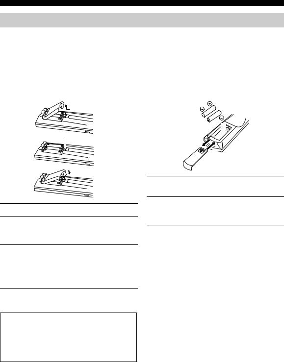
Installing batteries in the remote controls
Notes on batteries
•Change all of the batteries if you notice the following conditions: the operation range of the remote control decreases, the indicator does not flash or its light becomes dim.
•Do not use old batteries together with new ones.
•Do not use different types of batteries (such as alkaline and manganese batteries) together. Read the packaging carefully as these different types of batteries may have the same shape and color.
•If the batteries have leaked, dispose of them immediately. Avoid touching the leaked material or letting it come into contact with clothing, etc. Clean the battery compartment thoroughly before installing new batteries.
■ Remote control |
■ GUI remote control |
 RESET button

 2 1
2 1 
3
1Open the battery compartment cover.
2Insert three supplied batteries (AA, LR6) according to the polarity markings (+ and –) on the inside of the battery compartment.
3After new batteries are correctly inserted, press the RESET button in the battery compartment using a ball point pen or similar object.
(This does not clear the contents of the memory.)
4Replace the cover by pressing until it snaps into place.
If the remote control is without batteries for more than 3 minutes, or if exhausted batteries remain in the remote control, the contents of the memory may be cleared. If the memory is cleared, insert new batteries, set up the manufacturer code(s) and program any acquired functions that may have been cleared.
1Press the  part and slide the battery compartment cover off.
2Insert two supplied batteries (AAA, R03) according to the polarity markings (+ and –) on the inside of the battery compartment.
3Slide the cover back until it snaps into place.
4

CONTROLS AND FUNCTIONS
Front panel
1 |
2 3 |
4 |
|
|
5 6 7 8 9 0 A B |
C |
||||||
|
PURE DIRECT |
|
|
REC OUT/ZONE 2 |
|
|
|
MULTI JOG |
BALANCE |
VOLUME |
||
|
|
|
|
|
SOURCE/REMOTE |
|
|
|
|
|||
|
|
|
|
DTV/LD |
DVD |
|
|
|
|
|
|
|
|
2CH/MULTI CH |
SPEAKERS |
CABLE |
|
MD/TAPE |
|
MULTI CH |
DSP |
|
|
|
|
|
A |
B |
SAT |
|
CD-R |
INPUT MODE |
INPUT |
STRAIGHT PROGRAM |
|
|
|
|
|
INPUT SELECTOR |
|
|
VCR 1 |
|
CD |
|
|
|
|
TONE |
|
|
|
|
|
|
|
|
|
|
|
|
|
|
|
|
|
|
VCR 2 |
|
TUNER |
|
|
EFFECT |
|
CONTROL |
|
|
|
|
|
DVR |
|
PHONO |
|
|
|
|
|
|
|
|
|
|
VIDEO AUX |
|
|
|
|
|
|
|
|
|
STANDBY |
|
|
|
|
|
|
|
|
|
|
|
|
/ON |
|
|
SILENT |
OPTIMIZER |
|
|
VIDEO AUX |
|
|
|
|
|
|
|
|
|
|
|
|
|
||||
|
|
|
|
|
|
MIC |
|
|
|
|
|
|
|
|
|
PHONES |
|
|
S VIDEO |
VIDEO |
L AUDIO R |
OPTICAL |
|
|
|
|
|
D |
|
E F G |
|
|
H |
|
|
|
||
1 STANDBY/ON |
|
|
|
|
|
|
6 INPUT MODE |
|
|
|||
Turns on this unit or sets it to the standby mode. When you turn on this unit, you will hear a click and there will be a delay of a few seconds before this unit can reproduce sound.
Note
In standby mode, this unit consumes a small amount of power in order to receive infrared-signals from the remote controls.
2 INPUT SELECTOR
Selects the input source you want to listen to or watch.
3 PURE DIRECT 2CH/MULTI CH
Turns on or off the 2-channel/multi-channel PURE DIRECT mode (see page 43).
4 Remote control sensor
Receives signals from the remote controls.
5 Front panel display
Shows information about the operational status of this unit.
Sets the priority for the type of input signal (AUTO, i.LINK, DTS, DIGITAL, D.D.RF, ANALOG) received when one component is connected to two or more input jacks on this unit (see page 44).
7 MULTI CH INPUT
Selects the source connected to the MULTI CH INPUT jacks. This source takes priority over the source selected with INPUT SELECTOR (or the input selector buttons on the remote control).
8 STRAIGHT/EFFECT
Switches the sound fields off or on. When STRAIGHT is selected, input signals (2-channel or multi-channel) are output directly from their respective speakers without effect processing.
9 DSP PROGRAM
Press this button before rotating MULTI JOG to select sound field programs.
INTRODUCTION
English
5

CONTROLS AND FUNCTIONS
0 MULTI JOG
Rotate to select or adjust items when used with the DSP PROGRAM, BALANCE or TONE CONTROL buttons.
A BALANCE
Adjusts the left/right balance of the front, presence, surround and surround back speakers.
B TONE CONTROL
Press this button before rotating MULTI JOG to adjust the bass/treble balance for the front left/right, center and subwoofer channels (see page 38).
C VOLUME
Controls the output level of all audio channels. This does not affect the REC OUT level.
D SPEAKERS A/B
Turns on or off the set of front speakers connected to the A and/or B terminals on the rear panel each time the corresponding button is pressed.
E  PHONES jack
Outputs audio signals for private listening with headphones. When you connect headphones, no signals are output to the OUTPUT jacks or to the speakers.
F OPTIMIZER MIC jack
Use to connect and input audio signals from the supplied microphone for the AUTO SETUP function (see page 31).
G REC OUT/ZONE 2
Selects the source you want to direct to the audio/video recorder and ZONE 2 outputs independently of the source you are listening to or watching in the main room. When set to the SOURCE/REMOTE position, the input source is directed to all outputs. The source in Zone 2 and the source you record are always identical.
H VIDEO AUX jacks
Inputs audio and video signals from a portable external source such as a game console. To reproduce source signals from these jacks, select V-AUX as the input source.
■ Opening and closing the front panel door
When you want to use the controls behind the front panel door, open the door by gently pressing on the lower part of the panel. Keep the door closed when not using these controls.
To open, press gently on the lower part of the panel.
6

Remote control
This section describes the functions of each control on the remote control. See “REMOTE CONTROL FEATURES” on page 80 to operate other components with this remote control.
1 |
|
|
|
|
|
|
2 |
|
|
|
|
|
F |
3 |
|
|
|
|
|
G |
|
|
|
|
MACRO |
H |
|
|
TRANSMIT RE-NAME CLEAR LEARN |
MACRO |
OFF ON |
|||
|
|
|||||
4 |
SYSTEM |
STANDBY |
V-AUX |
TUNER |
PHONO |
I |
|
POWER |
|||||
5 |
|
|
|
|
|
|
|
CABLE |
SAT |
MD/TAPE |
CD-R |
CD |
|
|
DTV/LD |
VCR 1 |
VCR 2 |
DVR |
DVD |
J |
6 |
|
|
PURE DIRECT |
|
MULTI CH IN |
|
|
|
|
|
|
K |
|
|
|
|
TITLE |
|
|
|
7 |
|
|
|
ENTER |
|
L |
|
|
|
|
|
||
8 |
SOURCE |
INPUT MODE |
TOP |
|
EXIT |
M |
|
|
DISPLAY |
MENU |
|
SOUND |
N |
9 |
SELECT |
SEARCH |
– CHAPTER + |
|||
0 |
POWER |
REC |
STOP |
PAUSE |
PLAY |
|
10KEY AMP |
STEREO |
HALL 1 |
HALL 2 |
CHURCH |
|
|
A |
1 |
2 |
|
3 |
4 |
|
|
|
|
||||
|
JAZZ |
ROCK |
MUSIC |
ENTERTAIN |
O |
|
|
5 |
6 |
|
7 |
8 |
|
EX/ES |
MOVIE |
THX |
|
/DTS |
NIGHT |
|
B |
9 |
0 |
|
+10 |
+100 |
|
|
|
|
||||
CHP/INDEX |
|
|
|
|
|
|
|
A/B/C/D/E |
PRESET |
|
|
|
P |
|
TV INPUT |
|
|
MUTE |
|
Q |
TV VOL |
|
CH |
|
|
VOLUME |
|
|
TV MUTE |
|
STRAIGHT |
|
|
|
|
|
DISC |
|
EFFECT |
|
R |
ON SCREEN |
|
|
|
|
|
|
C |
|
|
|
|
|
S |
SLEEP |
TEST |
A |
SPEAKERS |
B |
||
|
|
|||||
D |
|
|
|
|
|
|
E |
|
PUSH |
|
|
|
|
t
1 Infrared window
Outputs infrared control signals. Aim this window at the component you want to operate.
2 RE-NAME
Used for changing the input source name in the display window (see page 83).
CONTROLS AND FUNCTIONS
3 TRANSMIT indicator
Flashes while the remote control is sending signals.
4 STANDBY
Sets this unit in the standby mode.
5SYSTEM POWER
Turns on this unit’s power.
6PURE DIRECT
Turns on or off the 2-channel/multi-channel PURE DIRECT mode (see page 43).
7 Display window
Shows the name of the selected source component that you can control.
8 SOURCE SELECT k/n
Selects another component that you can control independently of the input component selected with the input selector buttons.
9 LIGHT
Press to momentarily light up the display window and buttons on this remote control.
0 INPUT MODE
Sets the priority for the type of input signal (AUTO, i.LINK, DTS, DIGITAL, D.D.RF, ANALOG) received when one component is connected to two or more input jacks on this unit (see page 44).
A 10KEY/AMP
Slide to 10KEY to select a numeric button or operate the component selected using the input selector buttons. Slide to AMP to operate this unit.
B EX/ES
Switches between 5.1- and 6.1/7.1-channel playback of multi-channel software.
C ON SCREEN
Selects the GUI display mode for your video monitor.
D SLEEP
Sets the sleep timer.
E TEST
Outputs the test tone to adjust the speaker levels.
F CLEAR
Used for clearing functions acquired when using the learn and rename features and setting manufacturer codes (see page 86).
INTRODUCTION
English
7

CONTROLS AND FUNCTIONS
G LEARN
Used for setting up the manufacturer code or for programming the functions of other remote controls (see pages 81 and 82).
H MACRO
Used to program a series of operations for control by a single button (see page 84).
I MACRO ON/OFF
Turns the macro function on and off.
J Input selector buttons
Selects the input source and changes the control area.
K MULTI CH IN
Selects the source connected to the MULTI CH INPUT jacks. This source takes priority over the source selected with INPUT SELECTOR (or the input selector buttons on the remote control).
L Operation buttons
Operate various parameters and commands shown in the on-screen display.
M EXIT
Press to exit the on-screen display menus.
N TOP
Press to display the top level of the on-screen display menus.
O Sound field program
Use to select sound field programs.
P MUTE
Mutes the sound. The MUTE indicator turns on when the MUTE function is on. Press again to restore the audio output to the previous volume level.
Q VOLUME +/–
Increases or decreases the volume level.
R STRAIGHT/EFFECT
Switches the sound fields off or on. When STRAIGHT is selected, input signals (2-channel or multi-channel) are output directly from their respective speakers without effect processing.
S SPEAKERS A/B
Turn on or off the set of front speakers connected to the A and/or B terminals on the rear panel each time the corresponding button is pressed.
T Cover
Slide down to use the concealed buttons for various setup and parameter operations.
GUI remote control
This section describes the controls and functions of the GUI remote control. See “USING THE GUI REMOTE CONTROL” on page 29 for details.
SYSTEM |
STANDBY |
POWER |
|
1 |
5 |
2 |
ENTER |
|
3 |
|
|
4 |
TOP |
EXIT |
|
|
|
|
+ |
|
|
VOL |
6 |
–
MUTE
7
1SYSTEM POWER
Turns on this unit’s power.
2Multi-control/ENTER
Tilt up/down or left/right to navigate through the various parameters and commands shown in the on-screen display. Press to choose the selected item in the on-screen display.
3 TOP
Press to display the top level of the on-screen display menus.
4 EXIT
Press to exit the on-screen display menus.
5 STANDBY
Sets this unit in the standby mode.
6 VOLUME +/–
Increases or decreases the volume level.
7 MUTE
Mutes the sound. The MUTE indicator turns on when the MUTE function is on. Press again to restore the audio output to the previous volume level.
8
Using the remote controls
30 |
30 |
Approximately 6 m (20 ft) |
The remote controls transmit directional infrared beams. Be sure to aim the remote controls directly at the remote control sensor on the main unit during operation.
■ Handling the remote controls
•Do not spill water or other liquids on the remote controls.
•Do not drop the remote controls.
•Do not leave or store the remote controls in the following types of conditions:
–high humidity such as near a bath
–high temperature such as near a heater or stove
–extremely low temperatures
–dusty locations
CONTROLS AND FUNCTIONS
INTRODUCTION
English
9

CONTROLS AND FUNCTIONS
Front panel display
1 2 3 4 5 6 7 8 9 |
|
|
0 |
|
A B C |
||||||||
MULTI CH |
V–AUX |
DVR |
VCR 2 |
VCR 1 |
SAT CABLE |
DTV/LD |
DVD |
MD/TAPE |
CD–R |
TUNER |
CD PHONO |
||
MATRIX DISCRETE HiFi DSP |
|
|
|
|
|
|
|
|
|
MUTE |
|
||
|
|
|
|
|
|
|
|
|
VOLUME |
|
|||
|
2496 |
VIRTUAL |
NIGHT |
SILENT |
|
|
|
|
|
|
|
|
|
DIGITAL |
EX |
|
SP |
|
|
|
|
|
|
|
LFE |
||
PL |
PL |
|
OPTIMIZER |
A B |
|
|
|
|
|
|
|
L C |
R |
THX PCM |
|
SLEEP |
|
|
|
|
|
|
|
||||
|
|
|
|
|
|
|
|
|
SL SB |
SR |
|||
|
|
|
|
|
|
|
|
|
|
|
|||
|
|
|
|
ZONE2 |
|
|
|
|
|
|
|
||
|
|
|
|
|
|
|
|
|
|
|
|
|
|
D |
E F |
G |
I |
|
|
|
|
J |
|
|
K |
|
|
|
|
|
|
H |
|
|
|
|
|
|
|
|
|
1 i.LINK indicator
Lights up when this unit is playing back i.LINK signals.
2 Decoder indicators
When any of this unit’s decoders function, the respective indicator lights up.
3 HiFi DSP
Lights up when you select a HiFi DSP sound field program.
D THX indicators
Lights up when a THX program is selected.
E PCM indicator
Lights up when this unit is reproducing PCM (pulse code modulation) digital audio signals.
F Sound field indicators
Lights to indicate the active DSP sound fields.
Presence DSP sound field
4 VIRTUAL indicator
Lights up when Virtual CINEMA DSP is active (see page 42).
5 CINEMA DSP indicator
Lights up when you select a CINEMA DSP sound field program.
6 NIGHT indicator
Lights up when you select the night listening mode.
7 SILENT CINEMA indicator
Lights up when headphones are connected and a sound field program selected (see page 38).
8 Headphones indicator
Lights up when headphones are connected.
9 SP A B indicators
Lights up according to the set of front speakers selected. Both indicators light up when both sets of speakers are selected, or when bi-wiring.
0 Input source indicators
A cursor lights to show the current input source.
AVOLUME level indicators
Indicates the volume level.
BMUTE indicator
Lights up when the MUTE function is on.
C LFE indicator
Lights up when the input signal contains the LFE signal.
|
Listening position |
Surround left |
Surround right |
DSP sound field |
DSP sound field |
Surround back DSP sound field
G OPTIMIZER indicator
Lights up during the auto setup procedure and when the auto setup speaker settings are used without any modifications.
H ZONE 2 indicator
Lights up when Zone 2 power is on.
I SLEEP indicator
Lights up when the sleep timer is on.
J Multi-information display
Shows the current sound field program name and other information when adjusting or changing settings.
K Input channel indicators
Indicates the channel component of the current digital input signal.
10
CONTROLS AND FUNCTIONS
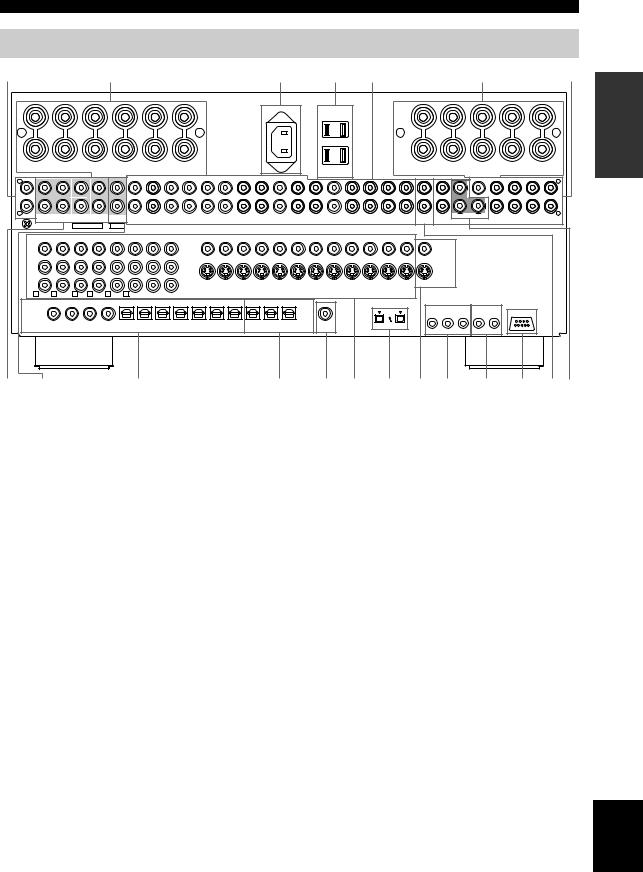
Rear panel
1 |
|
|
2 |
|
|
|
|
|
3 |
|
4 |
5 |
|
|
|
|
2 |
|
|
6 |
|
|
|
|
|
|
|
|
|
|
AC IN |
|
|
|
|
|
|
|
|
|
|
|
|
+ |
|
|
|
|
|
|
+ |
|
|
|
|
|
|
+ |
|
|
|
|
|
|
+ |
R |
|
|
|
|
|
R |
|
|
|
|
|
|
L |
|
|
|
|
|
|
L |
|
– |
|
|
|
|
|
|
– |
|
|
|
|
|
|
– |
|
|
|
|
|
|
– |
|
PRESENCE |
SURROUND |
SURROUND |
CENTER |
FRONT |
FRONT |
|
|
|
|
|
|
|
|
FRONT |
|
FRONT |
SURROUND |
SURROUND |
PRESENCE |
|
|
/ZONE 2 |
BACK |
|
|
B |
A |
|
|
|
|
|
|
|
|
A |
|
B |
|
|
BACK |
/ZONE 2 |
|
|
|
SPEAKERS |
|
|
|
|
|
AC OUTLETS |
|
|
|
SPEAKERS |
|
(SINGLE) |
|
|||||
|
|
|
|
|
|
|
|
AUDIO |
|
|
|
|
|
|
|
|
(FRONT) |
||||
|
(SINGLE) |
CENTER |
|
|
|
|
|
|
|
|
|
|
|
|
|
OUT |
|
(SINGLE) |
|||
L |
|
|
|
|
|
|
|
|
|
|
|
|
|
|
|
L |
|||||
|
|
|
|
|
|
|
|
|
|
|
|
|
|
|
|
|
|
|
|
||
R |
|
|
|
|
|
|
|
|
|
|
|
|
|
|
|
|
POWER AMP IN |
|
|
R |
|
PHONO SURROUND |
SURROUND SUBWOOFER FRONT |
PURE DIRECT |
|
IN(PLAY) OUT(REC) |
IN(PLAY) OUT(REC) |
|
|
|
|
IN(PLAY) OUT(REC) |
IN(PLAY) OUT(REC) |
IN(PLAY) OUT(REC) |
OUT |
OUT |
|
SURROUND |
(REAR) |
||||
|
BACK |
|
|
TUNER |
CD |
MD/TAPE |
CD-R |
DVD |
DTV/LD |
CBL |
SAT |
VCR 1 |
VCR 2 |
DVR |
ZONE 2 |
|
FRONT |
CENTER SURROUND |
BACK |
PRESENCE SUBWOOFER |
|
|
GND |
MULTI CH INPUT |
2CH IN |
|
|
|
|
|
|
|
|
|
|
|
|
|
|
|
|
|
|
|
|
|
COMPONENT VIDEO |
|
|
|
|
|
|
|
|
|
|
|
|
VIDEO |
|
|
|
|
|
|
|
|
|
|
||
Y |
|
|
|
|
|
|
|
|
|
|
|
|
|
|
|
|
|
|
|
|
|
|
|
VIDEO |
|
|
|
|
|
|
|
|
|
|
|
|
|
|
|
|
|
|
|
|
|
|
|
|
|
|
|
|
|
|
|
|
|
PB |
|
|
|
|
|
|
|
|
|
|
|
|
|
|
|
|
|
|
|
|
|
|
|
|
|
|
|
|
PR |
|
|
|
|
|
|
|
|
S1/S2 |
1–MONITOR OUT–2 |
DVD |
DTV/LD |
CBL |
SAT |
IN VCR 1 |
OUT |
IN VCR 2 OUT |
IN DVR |
OUT |
ZONE 2 |
S.VIDEO |
|
|
|
|
|||
|
|
|
|
|
|
|
|
|
|
|
|
|
|
|
|
|
|
|
|
|
|
|
|
|
|
|||
A DVD |
B DTV/LD |
C CBL |
D SAT |
E VCR1 |
F DVR |
1–MONITOR OUT–2 |
|
|
|
|
|
|
|
|
|
|
|
|
|
|
|
|
|
|
|
|
||
|
|
|
|
|
DIGITAL INPUT |
|
|
|
|
|
|
|
|
|
DIGITAL OUTPUT |
|
|
|
|
|
|
|
|
|
|
|||
DTV/LD |
|
CD |
DVD |
DVR |
CD |
CD-R |
DVD |
DTV |
CBL |
SAT |
DVR |
|
CD-R |
MD/TAPE |
DVR |
ZONE 2 |
|
|
|
|
|
REMOTE |
|
CONTROL OUT |
|
|||
LD |
|
|
|
|
|
|
|
|
|
|
|
|
|
|
|
|
|
|
|
|
S400 |
|
|
|
|
|||
q RF— |
|
|
|
|
|
|
|
|
|
|
|
|
|
|
|
|
|
|
|
|
|
|
1 |
2 |
1 |
2 |
RS–232C |
|
|
|
|
|
|
|
|
|
|
|
|
|
|
|
|
|
|
|
|
|
|
|
|
||||||
(AC-3) |
|
|
|
|
|
5 |
6 |
7 |
8 |
9 |
|
0 |
A |
B |
|
C |
D |
|
|
|
|
|
|
|
|
|
|
|
|
1 |
2 |
3 |
4 |
|
|
|
|
|
(AUDIO) |
|
|
|
|
|
|
|
|||||||||||
COAXIAL |
|
|
|
|
|
|
|
|
|
|
|
|
|
|
|
|
OPTICAL |
COAXIAL |
|
|
|
|
IN |
OUT |
IN |
+12V 15mA MAX |
|
|
|
|
|
|
|
|
|
|
|
|
|
|
|
|
|
|
|
|
|
|
|
|
|
|
|||||
7 8 |
|
|
|
|
|
9 |
|
|
|
|
|
|
|
|
0 A B C D E F G H I |
|||||||||||||
INTRODUCTION
1 PHONO
See page 24 for connection information.
2 Speaker terminals
See page 14 for connection information.
3 AC INLET
Use this inlet to plug in the supplied power cable (see page 27).
4 AC OUTLET(S)
Use to supply power to your other A/V components (see page 27).
5 Audio component jacks
See pages 24 and 25 for connection information.
6 Pre out jacks
See page 26 for connection information.
7 MULTI CH INPUT jacks
See page 18 for connection information.
8 2CH IN jacks
See page 18 for connection information.
9 DIGITAL INPUT jacks
See pages 17, 19-21 and 23-25 for details.
0 DIGITAL OUTPUT jacks
See pages 23 and 25 for details.
A ZONE 2 COAXIAL OUT
See page 93 for details.
B Video component jacks
See pages 17 and 19-23 for connection information.
C i.LINK connectors
See pages 26 and 96 for connection information.
DZONE 2 video jacks
See page 93 for details.
EREMOTE IN/OUT jacks
See page 93 for details.
FCONTROL OUT jacks
These are control expansion terminals for commercial use.
G RS-232C terminal
This is a control expansion terminal for commercial use. Consult you dealer for details.
HZONE 2 audio jacks
See page 93 for details.
IFRONT IN/CENTER IN
See page 26 for connection information.
< General models only >
VOLTAGE SELECTOR
See page 27 for details.
English
11

SPEAKER SETUP
Speaker placement
Since CINEMA DSP and THX are different surround post-processing technologies, we recommend the following speaker setup in order to enjoy the best surround sound of each technology.
■ CINEMA DSP speaker layout
PL |
PR |
|
C |
FL |
FR |
30˚
SL |
|
SR |
|
|
60˚ |
SL |
80˚ |
SR |
|
SBL |
SBR |
more than 30 cm (12 in.)
y
The speaker layout above shows the standard ITU-R speaker setup. You can use it to enjoy CINEMA DSP, multi-channel audio sources and THX.
1.8 m (6 ft) |
1.8 m (6 ft) |
Front speakers (FR and FL)
The front speakers are used for the main source sound. Place these speakers an equal distance from the ideal listening position. The distance of each speaker from each side of the video monitor should be the same.
Center speaker (C)
The center speaker is for the center channel sounds (dialog, vocals, etc.). Align the front face of the center speaker with the front face of your video monitor. Place the speaker centrally between the front speakers and as close to the monitor as possible, such as directly over or under it.
Surround speakers (SR and SL)
The surround speakers are used for effect and surround sounds. Place these speakers behind your listening position, facing slightly inwards, about 1.8 m (6 ft) above the floor.
Surround back speakers (SBR and SBL)
The surround back speakers supplement the surround speakers and provide for more realistic front-to-back transitions. Place these speakers directly behind the listening position and at the same height as the surround speakers. They should be positioned at least 30 cm (12 in.) apart. Ideally, they should be positioned at the same width as the front speakers.
Subwoofer
The use of a subwoofer, such as the YAMAHA Active Servo Processing Subwoofer System, is effective not only for reinforcing bass frequencies from any or all channels, but also for high fidelity reproduction of the LFE (lowfrequency effect) channel included in Dolby Digital and DTS software. The position of the subwoofer is not so critical, because low bass sounds are not highly directional. But it is better to place the subwoofer near the front speakers. Turn it slightly toward the center of the room to reduce wall reflections.
Presence speakers (PR and PL)
Presence speakers supplement the sound from the front speakers with extra ambient effects produced by CINEMA DSP (see page 38). These effects include sounds that filmmakers intend to locate a little farther back behind the screen in order to create more theater-like ambience. Place these speakers at the front of the room about 0.5 - 1 m
(1 - 3 ft) outside the front speakers, facing slightly inwards, and about 1.8 m (6 ft) above the floor.
12
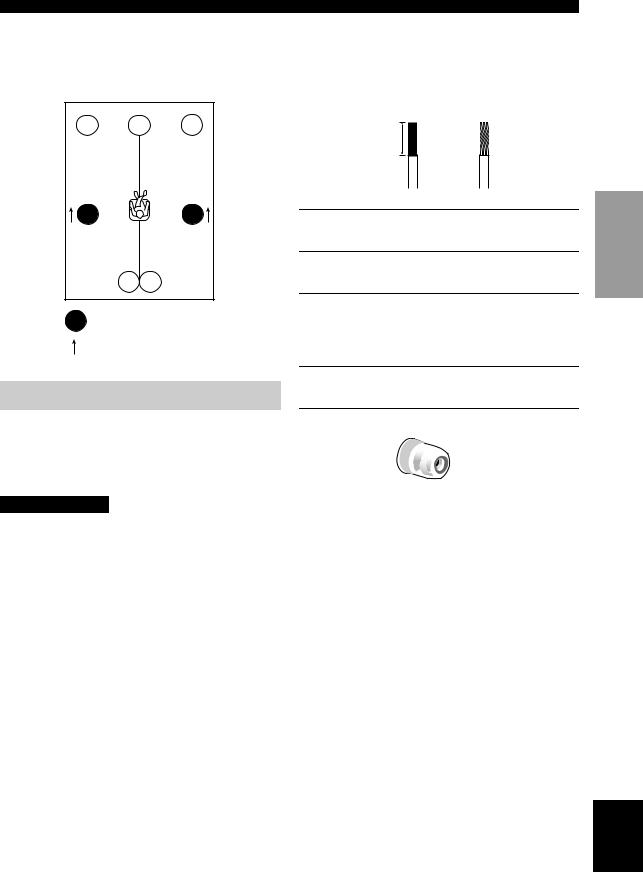
■ Di-pole speaker layout
Either di-pole or direct radiating speaker types can be used for THX surround. If you choose di-pole speakers, please place the surround and surround back speakers according to the speaker layout below.
FL |
C |
FR |
SL |
SR |
SBL SBR
: Di-pole speaker
: Direction of di-pole speaker
Speaker connections
Be sure to connect the left channel (L), right channel (R), “+” (red) and “–” (black) properly. If the connections are faulty, no sound can be heard from the speakers, and if the polarity of the speaker connections is incorrect, the sound will be unnatural and lack bass.
CAUTION
•If you intend to use 6-ohm speakers, be sure to set this unit’s speaker impedance setting to 6 ohms before using (see page 28).
•Before connecting the speakers, make sure that this unit’s power is off.
•Do not let the bare speaker wires touch each other or any metal part of this unit. This could damage this unit and/or the speakers.
•Use magnetically shielded speakers. If this type of speaker still creates interference with the monitor, place the speakers away from the monitor.
SPEAKER SETUP
A speaker cord is actually a pair of insulated cables running side by side. One cable is colored or shaped differently, perhaps with a stripe, groove or ridges.
Connect the striped (grooved, etc.) cable to the “+” (red) terminals on this unit and your speaker. Connect the plain cable to the “–” (black) terminals.
10 mm (3/8")
1 2
1Remove approximately 10 mm (3/8") of insulation from each of the speaker cables.
2Twist the exposed wires of the cable together to prevent short circuits.
3Unscrew the knob.
y
The supplied speaker terminal wrench is useful for screwing or unscrewing knobs.
4Insert one bare wire into the hole in the side of each terminal.
5Tighten the knob to secure the wire.
5 |
4
3
Red: positive (+) |
Speaker |
Black: negative (–) |
terminal |
|
wrench |
Banana plug connections
(With the exception of U.K. and Europe models) First, tighten the knob and then insert the banana plug connector into the end of the corresponding terminal.
Banana plug
(With the exception of U.K. and Europe models)
PREPARATION
English
13

SPEAKER SETUP
Presence |
|
Front right |
Front left |
Presence |
||||||||
|
right |
|
|
left |
||||||||
speaker |
Center |
speaker (A) |
speaker (A) |
speaker |
||||||||
|
|
|
|
|
|
|||||||
|
|
|
speaker |
|
|
|
|
|
|
|
|
|
|
|
|
|
|
|
|
|
|
|
|
|
|
10 |
|
|
|
|
|
|
|
5 |
|
|
|
|
3 |
4 |
|
|
|
|
11 |
||
|
|
|
|
|
|
|
|
|
|
|
|
|
|
|
|
|
|
|
|
|
|
Left |
Right |
subwoofer |
subwoofer |
system |
system |
2 |
1 |
Front speakers (B)
+ |
+ |
+ |
+ |
R |
|
|
|
|
R |
L |
|
|
|
L |
– |
|
|
|
|
– |
– |
|
|
|
– |
PRESENCE |
SURROUND |
SURROUND |
CENTER |
FRONT |
FRONT |
FRONT |
FRONT |
SURROUND |
SURROUND |
PRESENCE |
/ZONE 2 |
BACK |
|
|
B |
A |
A |
B |
|
BACK |
/ZONE 2 |
|
|
SPEAKERS |
SPEAKERS |
(SINGLE) |
|
|||||
|
|
|
|
|
|
|
|
|||
|
|
|
|
|
|
|
|
|
|
R |
|
|
|
|
|
|
|
|
|
|
SUBWOOFER |
|
|
6 |
|
|
8 |
|
|
9 |
|
|
7 |
|
|
|
|
|
|
|
|
|
|
|
|
Surround back |
Surround |
Surround |
Surround back |
||||||||
right speaker |
|
right |
|
left |
left speaker |
||||||
|
|
|
speaker |
speaker |
|
|
|
||||
|
10 |
|
|
11 |
3 |
|
|
5 |
|
|
|
|
|
|
|
4 |
|
1 |
8 |
|
|
||
|
|
|
|
2 |
9 |
7 |
6 |
|
|
|
Speaker layout
14

■ FRONT terminals
Connect one or two speaker systems to these terminals. If you use only one speaker system, connect it to either of the FRONT A or B terminals.
Note
The Canada model cannot output to two separate speaker systems simultaneously.
Bi-wired connection
The unit also allows you to make bi-wired connections to one speaker system. Use two pairs of speaker cables for each speaker (one pair for the woofer and one pair for the tweeter/mid-range). To use the bi-wired connections, press SPEAKERS A and SPEAKERS B on the front panel so that both SP A and B light up on the front panel display.
Bi-wired connection
This unit
SPEAKER SETUP
■ PRESENCE/ZONE 2 terminals
Connect presence speakers to these terminals. You can also use these terminals for connecting Zone 2 speakers (see page 94).
Note
The presence speakers output ambient effects created by the DSP sound fields. They do not output sound when other sound fields are selected.
PREPARATION
■ CENTER terminals
Connect a center speaker to these terminals.
■ SURROUND terminals
Connect a surround speaker system to these terminals.
■ SUBWOOFER jacks
Connect one or two subwoofer(s) with built-in amplifier, such as the YAMAHA Active Servo Processing Subwoofer System, to the jack(s).
■ SURROUND BACK terminals
Connect a surround back speaker system to these terminals. If you only connect one surround back speaker, connect it to the left (L) terminals.
English
15

CONNECTIONS
Connecting components
CAUTION
Do not connect this unit or other components to the mains power until all connections between components are completed.
■ Signal directions and cable indications
audio signal direction |
|
|
|
|
|||
|
|
|
|
||||
video signal direction |
|
|
|
||||
|
|
|
|||||
For analog signals |
|
|
|
||||
left analog cables |
|
|
L |
||||
|
|||||||
right analog cables |
|
|
R |
||||
|
|
||||||
For digital signals |
|
|
|
||||
optical cables |
|
|
|
O |
|||
|
|
|
|||||
coaxial cables |
|
|
|
C |
|||
|
|
|
|||||
For video signals |
|
|
|
||||
video cables |
|
|
|
|
V |
||
|
|
|
|
||||
S video cables |
|
|
|
|
|
S |
|
|
|
|
|
||||
|
|
|
|
|
|
|
V |
■ Analog jacks
You can input analog signals from audio components by connecting an audio pin cable to each of this unit’s analog jacks. Connect red plugs to the right jacks and white plugs to the left jacks.
■ Digital jacks
This unit has digital jacks for direct transmission of digital signals through either coaxial or fiber optic cables. You can use the digital jacks to input PCM, Dolby Digital and DTS bitstreams. When you connect components to both the COAXIAL and OPTICAL jacks, priority is given to the input signals from the COAXIAL jack. COAXIAL jacks are compatible with digital signals with sampling frequencies up to 192 kHz, and OPTICAL jacks with sampling frequencies up to 96 kHz.
Note
This unit handles digital and analog signals independently. Thus, audio signals input to the analog jacks are only output to the analog OUT (REC) jacks. Likewise audio signals input to the digital (OPTICAL or COAXIAL) jacks are only output to the DIGITAL OUTPUT jacks.
■ i.LINK jacks
This unit can be connected with i.LINK equipped components using 4-pin, S400 i.LINK cables. This connection enables you to send and receive digital audio at high speed and with high fidelity.
■ Video jacks
This unit has three types of video jacks. The signals input through any type of VIDEO IN jack can be output through any of the VIDEO (MONITOR OUT) jacks (automatic video conversion).
COMPONENT VIDEO
Y
PB |
S VIDEO |
VIDEO |
PR
VIDEO jack
For conventional composite video signals.
S VIDEO jack
For S video signals, separated into luminance (Y) and color (C) video signals to achieve high-quality color reproduction.
COMPONENT VIDEO jacks
For component signals, separated into luminance (Y) and color difference (PB, PR) to provide the best quality
in picture reproduction.
Notes
•When signals are input simultaneously through the COMPONENT VIDEO, S VIDEO and VIDEO jacks, the input priority is as follows: COMPONENT VIDEO, S VIDEO then VIDEO.
•Video signal conversion is only possible for signals input through the COMPONENT VIDEO jack when Resolution is set to 480i/576i. Signals will not be converted when Resolution is set to 480p/576p, 720p or 1080i (see page 72).
16
CONNECTIONS
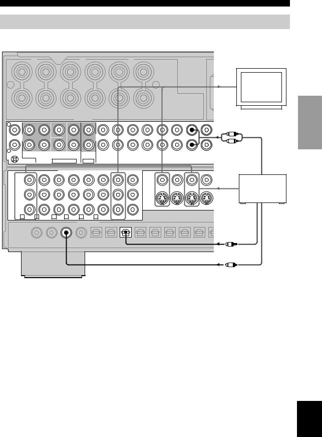
Connecting video components
■ Connections for DVD playback
|
AC I |
+ |
+ |
R |
|
|
|
|
R |
|
|
Video |
||
|
|
|
|
|
|
|
|
|
Video in |
monitor |
|
|
|
|
|
|
|
|
|
|
|
– |
|
|
|
|
|
|
– |
|
|
|
|
PRESENCE |
SURROUND |
SURROUND |
CENTER |
FRONT |
FRONT |
|
|
|
|
|
/ZONE 2 |
BACK |
|
|
B |
A |
|
|
|
|
|
|
|
SPEAKERS |
|
|
|
|
|||
|
|
|
|
|
|
|
|
|
||
L |
(SINGLE) |
CENTER |
|
|
|
|
|
|
|
|
|
|
|
|
|
|
|
|
|
|
|
|
|
|
|
|
|
|
|
|
R |
|
|
|
|
|
|
|
|
|
|
L |
|
R |
PHONO SURROUND |
SURROUND SUBWOOFER FRONT |
PURE DIRECT |
|
IN(PLAY) OUT(REC) |
IN(PLAY) OUT(REC) |
|
|
|
|
|
|
|
|
|
||||||
|
BACK |
|
|
TUNER |
CD |
MD/TAPE |
CD-R |
DVD |
DTV/LD |
|
|
GND |
MULTI CH INPUT |
2CH IN |
|
|
|
|
|
|
|
COMPONENT VIDEO |
Audio out |
Y |
|
|
|
|
|
|
|
|
|
|
|
|
|
|
|
|
|
|
|
|
|
|
|
|
|
|
|
|
|
|
|
|
|
DVD player |
|
PB |
|
|
|
|
|
|
|
|
|
|
|
|
|
|
|
Video out |
|
PR |
|
|
|
|
|
|
|
|
S1/S2 |
1–MONITOR OUT–2 |
DVD |
DTV/LD |
Optical out |
Coaxial out |
|||
A DVD |
B DTV/LD |
C CBL D SAT |
E VCR1 |
F DVR |
1–MONITOR OUT–2 |
|
|
|
|
|
|
|
|
||||
|
|
|
|
|
DIGITAL INPUT |
|
|
|
|
|
|
|
|
|
|
|
|
|
DTV/LD |
|
CD |
DVD |
DVR |
CD |
CD-R |
DVD |
DTV |
CBL |
SAT |
DVR |
|
CD-R |
MD/ |
|
|
LD |
|
|
|
|
|
|
|
|
|
|
|
|
|
|
|
|
|
q RF— |
|
|
|
|
|
|
|
|
|
|
|
|
|
|
|
|
|
(AC-3) |
|
|
|
|
|
5 |
6 |
7 |
8 |
9 |
|
0 |
A |
B |
|
|
|
|
1 |
2 |
3 |
4 |
|
|
|
|
|||||||||
COAXIAL |
|
|
|
|
|
|
|
|
|
|
O |
|
|||||
|
|
|
|
|
|
|
|
|
|
|
|
|
|
|
|
||
|
|
|
|
|
|
|
|
|
|
|
|
|
|
|
|
|
|
C
PREPARATION
English
17
CONNECTIONS
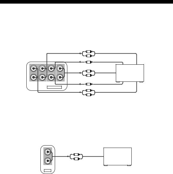
■ Connecting to the MULTI CH INPUT jacks
This unit is equipped with 8 additional input jacks (left and right FRONT, CENTER, left and right SURROUND, left and right SURROUND BACK and SUBWOOFER) for discrete multi-channel input from a universal disc player, external decoder, sound processor or pre-amplifier.
Connect the output jacks on your multi-disc player or external decoder to the MULTI CH INPUT jacks. Be sure to match the left and right outputs to the left and right input jacks for the front and surround channels.
For multi-channel input
|
R |
|
|
|
L |
Surround out |
|
(SINGLE) |
CENTER |
Center out |
|
|
R |
|
Universal disc |
|
|
player/External |
|
|
L |
Front out |
|
|
decoder |
||
|
|
|
SURROUND SURROUND SUBWOOFER |
FRONT |
BACK |
|
MULTI CH INPUT
 R
R
 L
L
Subwoofer out
Surround back out
■ Connecting to the 2CH IN jacks
This unit is equipped with 2 additional input jacks for discrete 2-channel input from a universal disc player, passive input selector or other high-speed audio component.
The signals input to these jacks can be chosen by pressing PURE DIRECT (see page 43). This feature provides the best possible sound quality from this unit.
Connect the output jacks on your multi-disc player or external decoder to the 2CH IN jacks.
For 2-channel input |
|
|
R |
|
Universal disc |
L |
2CH out |
player, etc. |
PURE DIRECT
2CH IN
18
CONNECTIONS
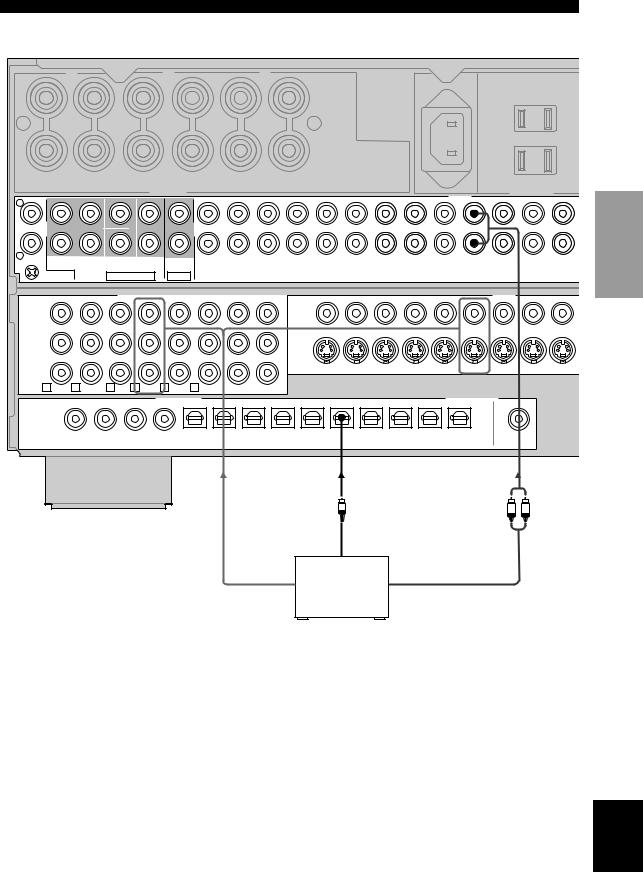
■ Connections for digital TV broadcasts or LD playback
|
AC IN |
+ |
+ |
R |
|
|
|
|
R |
|
|
|
|
|
|
||
– |
|
|
|
|
|
|
– |
|
|
|
|
|
|
|
PRESENCE |
SURROUND |
SURROUND |
CENTER |
FRONT |
FRONT |
|
|
|
|
|
|
|
|
/ZONE 2 |
BACK |
|
|
B |
A |
|
|
|
|
|
|
|
|
|
|
SPEAKERS |
|
|
|
|
|
AC OUTLETS |
|
|||
|
|
|
|
|
|
|
|
|
AUDIO |
|
|||
L |
(SINGLE) |
CENTER |
|
|
|
|
|
|
|
|
|
||
|
|
|
|
|
|
|
|
|
|
||||
|
|
|
|
|
|
|
|
|
|
|
|
|
|
R |
PHONO SURROUND |
SURROUND SUBWOOFER FRONT |
PURE DIRECT |
|
IN(PLAY) OUT(REC) |
IN(PLAY) OUT(REC) |
|
|
|
|
IN(PLAY) OUT(REC) |
IN(PLAY) |
|
|
|
|
|
|
|
||||||||
|
BACK |
|
|
TUNER |
CD |
MD/TAPE |
CD-R |
DVD |
DTV/LD |
CBL |
SAT |
VCR 1 |
VC |
|
GND |
MULTI CH INPUT |
2CH IN |
|
|
|
|
|
|
|
|
|
|
|
|
|
COMPONENT VIDEO |
|
|
|
|
|
|
|
|
|
|
|
|
VIDEO |
|
|
|
|||
Y |
|
|
|
|
|
|
|
|
|
|
|
|
|
|
|
|
|
|
|
|
|
|
PB |
|
|
|
|
|
|
|
|
|
|
|
|
|
|
|
|
|
|
|
|
|
|
PR |
|
|
|
|
|
|
|
|
S1/S2 |
1–MONITOR OUT–2 |
DVD |
DTV/LD |
CBL |
SAT |
IN |
VCR 1 |
OUT |
IN |
VCR |
|||
|
|
|
|
|
|
|
|
|
|
|
|
|
|
|
|
|
|
|
|
|
||
A DVD |
B DTV/LD |
C CBL |
D SAT |
E VCR1 |
F DVR |
1–MONITOR OUT–2 |
|
|
|
|
|
|
|
|
|
|
|
|
|
|||
|
|
|
|
|
DIGITAL INPUT |
|
|
|
|
|
|
|
|
|
DIGITAL OUTPUT |
|
|
|
|
|||
|
DTV/LD |
|
CD |
DVD |
DVR |
CD |
CD-R |
DVD |
DTV |
CBL |
SAT |
DVR |
|
CD-R |
MD/TAPE |
DVR |
|
ZONE 2 |
|
|
|
|
LD |
|
|
|
|
|
|
|
|
|
|
|
|
|
|
|
|
|
|
|
|
|
|
q RF— |
|
|
|
|
|
|
|
|
|
|
|
|
|
|
|
|
|
|
|
|
|
|
(AC-3) |
|
|
|
|
|
5 |
6 |
7 |
8 |
9 |
|
0 |
A |
B |
|
C |
D |
|
|
|
|
|
|
1 |
2 |
3 |
4 |
|
|
|
|
|
|
|
|||||||||||
COAXIAL |
|
|
|
|
|
|
|
|
|
|
|
|
|
|
|
|
|
|||||
|
|
|
|
|
|
|
|
|
|
|
|
|
|
|
|
OPTICAL |
|
COAXIAL |
|
|
|
|
|
|
|
|
|
|
|
|
|
|
|
|
|
|
|
|
|
|
|
|
|
||
|
|
|
|
|
|
|
|
C |
O |
|
|
|
|
|
|
|
R |
L |
|
|
|
|
|
|
|
|
|
|
|
|
|
|
|
|
|
|
|
|
|
|
|
|
|||
* |
|
|
|
|
|
Coaxial out |
|
Optical out |
|
|
|
|
|
|
|
|
|
|
|
|
||
|
|
DTV tuner/ |
|
|
Video out |
|
|
LD player |
|
|
|
|
|
|
|
|
Audio out |
|
|
|
|
|
|
|
|
|
|
|
|
*A demodulator circuit is built into the Dolby Digital RF input so you can connect it directly to the Dolby Digital RF signal output on your LD player. Make sure you set Coaxial Input to 1LD-RF in the Assign system parameter (page 59).
PREPARATION
English
19

CONNECTIONS
■ Connections for cable TV broadcasts
|
AC IN |
+ |
+ |
R |
|
|
|
|
R |
|
|
|
|
|
|
||
– |
|
|
|
|
|
|
– |
|
|
|
|
|
|
|
PRESENCE |
SURROUND |
SURROUND |
CENTER |
FRONT |
FRONT |
|
|
|
|
|
|
|
|
/ZONE 2 |
BACK |
|
|
B |
A |
|
|
|
|
|
|
|
|
|
|
SPEAKERS |
|
|
|
|
|
AC OUTLETS |
|
|||
|
|
|
|
|
|
|
|
|
AUDIO |
|
|||
L |
(SINGLE) |
CENTER |
|
|
|
|
|
|
|
|
|
||
|
|
|
|
|
|
|
|
|
|
||||
|
|
|
|
|
|
|
|
|
|
|
|
|
|
R |
PHONO SURROUND |
SURROUND SUBWOOFER FRONT |
PURE DIRECT |
|
IN(PLAY) OUT(REC) |
IN(PLAY) OUT(REC) |
|
|
|
|
IN(PLAY) OUT(REC) |
IN(PLAY) |
|
|
|
|
|
|
|
||||||||
|
BACK |
|
|
TUNER |
CD |
MD/TAPE |
CD-R |
DVD |
DTV/LD |
CBL |
SAT |
VCR 1 |
VC |
|
GND |
MULTI CH INPUT |
2CH IN |
|
|
|
|
|
|
|
|
|
|
|
|
|
COMPONENT VIDEO |
|
|
|
|
|
|
|
VIDEO |
|
|
Y
PB
PR |
|
|
|
|
|
|
|
|
S1/S2 |
1–MONITOR OUT–2 |
DVD |
DTV/LD |
CBL |
SAT |
IN VCR 1 |
OUT |
IN VCR |
|||
|
|
|
|
|
|
|
|
|
|
|
|
|
|
|
|
|
|
|
||
A DVD |
B DTV/LD |
C CBL |
D SAT |
E VCR1 |
F DVR |
1–MONITOR OUT–2 |
|
|
|
|
|
|
|
|
|
|
|
|||
|
|
|
|
|
DIGITAL INPUT |
|
|
|
|
|
|
|
|
|
DIGITAL OUTPUT |
|
|
|||
|
DTV/LD |
|
CD |
DVD |
DVR |
CD |
CD-R |
DVD |
DTV |
CBL |
SAT |
DVR |
|
CD-R |
MD/TAPE |
DVR |
ZONE 2 |
|
|
|
LD |
|
|
|
|
|
|
|
|
|
|
|
|
|
|
|
|
|
|
|
|
q RF— |
|
|
|
|
|
|
|
|
|
|
|
|
|
|
|
|
|
|
|
|
(AC-3) |
|
|
|
|
|
5 |
6 |
7 |
8 |
9 |
|
0 |
A |
B |
|
C |
D |
|
|
|
|
1 |
2 |
3 |
4 |
|
|
|
|
|
|||||||||||
COAXIAL |
|
|
|
|
|
|
|
|
|
|
|
|
|
|
|
|||||
|
|
|
|
|
|
|
|
|
|
|
|
|
|
|
|
OPTICAL |
COAXIAL |
|
|
|
|
|
|
|
|
|
|
|
|
|
|
|
|
|
|
|
|
|
|
||
|
|
|
|
|
|
|
|
|
|
O |
|
|
|
|
|
|
R |
L |
|
|
|
|
|
|
|
|
|
|
|
|
|
|
|
|
|
|
|
|
|
||
Optical out
Cable TV tuner
Video out |
Audio out |
20
CONNECTIONS
■ Connections for satellite broadcasts
|
AC IN |
+ |
+ |
R |
|
|
|
|
R |
|
|
|
|
|
|
||
– |
|
|
|
|
|
|
– |
|
|
|
|
|
|
|
PRESENCE |
SURROUND |
SURROUND |
CENTER |
FRONT |
FRONT |
|
|
|
|
|
|
|
|
/ZONE 2 |
BACK |
|
|
B |
A |
|
|
|
|
|
|
|
|
|
|
SPEAKERS |
|
|
|
|
|
AC OUTLETS |
|
|||
|
|
|
|
|
|
|
|
|
AUDIO |
|
|||
L |
(SINGLE) |
CENTER |
|
|
|
|
|
|
|
|
|
||
|
|
|
|
|
|
|
|
|
|
||||
|
|
|
|
|
|
|
|
|
|
|
|
|
|
R |
PHONO SURROUND |
SURROUND SUBWOOFER FRONT |
PURE DIRECT |
|
IN(PLAY) OUT(REC) |
IN(PLAY) OUT(REC) |
|
|
|
|
IN(PLAY) OUT(REC) |
IN(PLAY) |
|
|
|
|
|
|
|
||||||||
|
BACK |
|
|
TUNER |
CD |
MD/TAPE |
CD-R |
DVD |
DTV/LD |
CBL |
SAT |
VCR 1 |
VC |
|
GND |
MULTI CH INPUT |
2CH IN |
|
|
|
|
|
|
|
|
|
|
|
|
|
COMPONENT VIDEO |
|
|
|
|
|
|
|
VIDEO |
|
|
Y
PB
PR |
|
|
|
|
|
|
|
|
S1/S2 |
1–MONITOR OUT–2 |
DVD |
DTV/LD |
CBL |
SAT |
IN VCR 1 |
OUT |
IN VCR |
||||
|
|
|
|
|
|
|
|
|
|
|
|
|
|
|
|
|
|
|
|
||
A DVD |
B DTV/LD |
C CBL |
D SAT |
E VCR1 |
F DVR |
1–MONITOR OUT–2 |
|
|
|
|
|
|
|
|
|
|
|
|
|||
|
|
|
|
|
DIGITAL INPUT |
|
|
|
|
|
|
|
|
|
DIGITAL OUTPUT |
|
|
|
|
||
|
DTV/LD |
|
CD |
DVD |
DVR |
CD |
CD-R |
DVD |
DTV |
CBL |
SAT |
DVR |
|
CD-R |
MD/TAPE |
DVR |
ZONE 2 |
|
|
||
LD |
|
|
|
|
|
|
|
|
|
|
|
|
|
|
|
|
|
|
|
|
|
q RF— |
|
|
|
|
|
|
|
|
|
|
|
|
|
|
|
|
|
|
|
|
|
(AC-3) |
|
|
|
|
|
5 |
6 |
7 |
8 |
9 |
|
0 |
A |
B |
|
C |
D |
|
|
|
|
|
1 |
2 |
3 |
4 |
|
|
|
|
|
|
|||||||||||
COAXIAL |
|
|
|
|
|
|
|
|
|
|
|
|
|
|
|
|
|||||
|
|
|
|
|
|
|
|
|
|
|
|
|
|
|
|
OPTICAL |
COAXIAL |
|
|
||
|
|
|
|
|
|
|
|
|
|
|
|
|
|
|
|
|
|
|
|||
|
|
|
|
|
|
|
|
|
|
|
O |
|
|
|
|
|
|
R |
L |
|
|
|
|
|
|
|
|
|
|
|
|
|
|
|
|
|
|
|
|
|
|
||
Optical out
Satellite tuner
Video out |
Audio out |
PREPARATION
English
21

CONNECTIONS
■ Connections for VCR playback and recording
|
AC IN |
+ |
+ |
R |
|
|
|
|
R |
|
|
|
|
|
|
||
– |
|
|
|
|
|
|
– |
|
|
|
|
|
|
|
PRESENCE |
SURROUND |
SURROUND |
CENTER |
FRONT |
FRONT |
|
|
|
|
|
|
|
|
/ZONE 2 |
BACK |
|
|
B |
A |
|
|
|
|
|
|
|
|
|
|
SPEAKERS |
|
|
|
|
|
AC OUTLETS |
|
|||
|
|
|
|
|
|
|
|
|
AUDIO |
|
|||
L |
(SINGLE) |
CENTER |
|
|
|
|
|
|
|
|
|
||
|
|
|
|
|
|
|
|
|
|
||||
|
|
|
|
|
|
|
|
|
|
|
|
|
|
R |
PHONO SURROUND |
SURROUND SUBWOOFER FRONT |
PURE DIRECT |
|
IN(PLAY) OUT(REC) |
IN(PLAY) OUT(REC) |
|
|
|
|
IN(PLAY) OUT(REC) |
IN(PLAY) |
|
|
|
|
|
|
|
||||||||
|
BACK |
|
|
TUNER |
CD |
MD/TAPE |
CD-R |
DVD |
DTV/LD |
CBL |
SAT |
VCR 1 |
VCR |
|
GND |
MULTI CH INPUT |
2CH IN |
|
|
|
|
|
|
|
|
|
|
|
|
|
COMPONENT VIDEO |
|
|
|
|
|
|
|
VIDEO |
|
|
Y
PB
PR |
|
|
|
|
|
|
|
|
S1/S2 |
1–MONITOR OUT–2 |
DVD |
DTV/LD |
CBL |
SAT |
IN VCR 1 |
OUT |
IN VCR |
|||
|
|
|
|
|
|
|
|
|
|
|
|
|
|
|
|
|
|
|
||
A DVD |
B DTV/LD |
C CBL |
D SAT |
E VCR1 |
F DVR |
1–MONITOR OUT–2 |
|
|
|
|
|
|
|
|
|
|
|
|||
|
|
|
|
|
DIGITAL INPUT |
|
|
|
|
|
|
|
|
|
DIGITAL OUTPUT |
|
|
|
||
|
DTV/LD |
|
CD |
DVD |
DVR |
CD |
CD-R |
DVD |
DTV |
CBL |
SAT |
DVR |
|
CD-R |
MD/TAPE |
DVR |
ZONE 2 |
|
|
|
LD |
|
|
|
|
|
|
|
|
|
|
|
|
|
|
|
|
|
|
|
|
q RF— |
|
|
|
|
|
|
|
|
|
|
|
|
|
|
|
|
|
|
|
|
(AC-3) |
|
|
|
|
|
5 |
6 |
7 |
8 |
9 |
|
0 |
A |
B |
|
C |
D |
|
|
|
|
1 |
2 |
3 |
4 |
|
|
|
|
|
|||||||||||
COAXIAL |
|
|
|
|
|
|
|
|
|
|
|
|
|
|
|
|||||
|
|
|
|
|
|
|
|
|
|
|
|
|
|
|
|
OPTICAL |
COAXIAL |
|
|
|
|
|
|
|
|
|
|
|
|
|
|
|
|
|
|
|
|
|
|
||
R L L R
Video out |
|
|
VCR |
|
|
Video in |
Audio out |
|
|
|
|
|
Audio in |
|
|
|
|
|
|
|
|
|
|
|
|
|
|
■ Connections to VIDEO AUX jacks (on the front panel)
Use these jacks to connect any video source, such as a game console or video camera, to this unit.
VIDEO AUX
S VIDEO |
VIDEO |
L AUDIO R |
OPTICAL |
S V L R O
Optical out |
|
Audio out R |
|
Audio out L |
Game console |
Video out |
or video |
camera |
|
S video out |
|
22

CONNECTIONS
■ Connections for DVD recorder playback and recording
|
|
|
|
|
AC IN |
|
|
|
|
+ |
+ |
|
|
|
|
R |
L |
|
|
|
|
– |
– |
D |
SURROUND |
CENTER |
FRONT |
FRONT |
FRONT |
|
SPEAKERS |
B |
A |
A |
|
|
|
|
AC OUTLETS |
||
CENTER |
AUDIO |
|
UBWOOFER FRONT |
PURE DIRECT |
|
|
IN(PLAY) OUT(REC) |
IN(PLAY) OUT(REC) |
|
|
|
|
IN(PLAY) OUT(REC) |
IN(PLAY) OUT(REC) |
IN(PLAY) OUT(REC) |
OUT |
|||||
|
|
|
|
|
|
|
TUNER |
CD |
MD/TAPE |
CD-R |
DVD |
DTV/LD |
CBL |
SAT |
VCR 1 |
VCR 2 |
DVR |
ZONE |
|
|
|
|
|
|
|
|
|
|
|
|
|
|
|
|
|
|
|||
MULTI CH INPUT |
|
2CH IN |
|
|
|
|
|
|
|
|
|
|
|
|
|
|
|||
|
|
|
|
|
|
|
|
|
|
|
|
|
|
|
|
|
|
|
|
|
|
COMPONENT VIDEO |
|
|
|
|
|
|
|
|
|
|
VIDEO |
|
|
|
|
||
|
|
|
|
|
|
|
|
|
|
|
|
|
|
|
|||||
|
|
|
|
|
|
S1/S2 |
1–MONITOR OUT–2 |
DVD |
DTV/LD |
CBL |
SAT |
IN |
VCR 1 |
OUT |
IN |
VCR 2 |
OUT |
IN |
DVR |
OUT |
ZONE |
|||
C CBL |
D SAT |
E VCR1 |
F DVR |
1–MONITOR OUT–2 |
|
|
|
|
|
|
|
|
|
|
|
|
|
|
|
|
|
|
||
|
|
DIGITAL INPUT |
|
|
|
|
|
|
|
|
|
DIGITAL OUTPUT |
|
|
|
|
|
|
|
|
|
|
||
|
DVD |
DVR |
CD |
CD-R |
DVD |
DTV |
CBL |
SAT |
DVR |
|
CD-R |
MD/TAPE |
DVR |
|
ZONE 2 |
|
|
|
|
|
|
|
|
|
|
|
|
|
|
|
|
|
|
|
|
|
|
|
|
|
|
|
|
|
|
S400 |
|
|
|
|
3 |
4 |
5 |
6 |
7 |
8 |
9 |
|
0 |
A |
B |
|
C |
D |
|
|
|
|
|
|
(AUDIO) |
|
|
|
|
|
|
|
|
|
|
|
|
|
|
|
|
|
|
|
|
|
|
|
|
||||
|
|
|
|
|
|
|
|
|
|
|
|
|
|
OPTICAL |
|
COAXIAL |
|
|
|
|
|
|
|
|
PREPARATION
O
R L  O L R
O L R
Optical out |
Optical in |
Audio out |
Video out |
|
DVD recorder |
Video out |
Video in |
C |
Audio in |
Coaxial out |
English
23
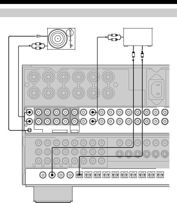
CONNECTIONS
Connecting audio components
■ Connections for audio playback
|
|
|
|
|
|
R |
CD player |
|
|
|
|
GND |
|
|
|
|
L |
|
|
||
|
|
|
|
|
|
|
|
|
||
|
R |
|
|
|
|
Audio out |
|
|
|
|
|
L |
|
|
|
|
|
|
|
|
|
|
Audio out |
Turntable |
|
|
|
Coaxial out |
Optical out |
|
||
|
|
|
|
|
|
|
C |
O |
|
|
|
|
|
|
|
|
|
|
AC IN |
|
|
+ |
|
|
|
|
|
|
+ |
|
|
|
R |
|
|
|
|
|
R |
|
|
|
|
– |
|
|
|
|
|
|
– |
|
|
|
|
PRESENCE |
SURROUND SURROUND |
CENTER |
FRONT |
FRONT |
|
|
|
|
|
|
/ZONE 2 |
BACK |
|
|
B |
A |
|
|
|
|
|
|
|
SPEAKERS |
|
|
|
|
|||
|
|
|
|
|
|
|
AUDIO |
|
||
L |
(SINGLE) |
|
CENTER |
|
|
|
|
|
|
|
|
|
|
|
|
|
|
|
|||
|
|
|
|
|
|
|
|
|
|
|
R |
|
|
|
|
|
IN(PLAY) OUT(REC) |
IN(PLAY) OUT(REC) |
|
|
|
PHONO SURROUND |
SURROUND |
SUBWOOFER FRONT |
PURE DIRECT |
|
|
|
|
|||
|
BACK |
|
|
TUNER |
CD |
MD/TAPE |
CD-R |
DVD DTV/LD |
CBL |
SAT |
|
GND |
|
MULTI CH INPUT |
2CH IN |
|
|
|
|
|
|
COMPONENT VIDEO
Y
PB
PR |
|
|
|
|
|
|
|
|
S1/S2 |
1–MONITOR OUT–2 |
DVD |
DTV/LD |
CBL |
SAT |
|||
|
|
|
|
|
|
|
|
|
|
|
|
|
|
|
|
||
A DVD |
B DTV/LD |
C CBL D SAT |
E VCR1 |
F DVR |
1–MONITOR OUT–2 |
|
|
|
|
|
|
|
|
||||
|
|
|
|
|
DIGITAL INPUT |
|
|
|
|
|
|
|
|
|
DIGITAL OUTP |
||
|
DTV/LD |
|
CD |
DVD |
DVR |
CD |
CD-R |
DVD |
DTV |
CBL |
SAT |
DVR |
|
CD-R |
MD/TAPE |
DVR |
|
LD |
|
|
|
|
|
|
|
|
|
|
|
|
|
|
|
|
|
q RF— |
|
|
|
|
|
|
|
|
|
|
|
|
|
|
|
|
|
(AC-3) |
|
|
|
|
|
5 |
6 |
7 |
8 |
9 |
|
0 |
A |
B |
|
C |
D |
|
1 |
2 |
3 |
4 |
|
|
|||||||||||
COAXIAL |
|
|
|
|
|
|
|
|
|
|
|
|
|||||
|
|
|
|
|
|
|
|
|
|
|
|
|
|
|
|
OPTICAL |
|
|
|
|
|
|
|
|
|
|
|
|
|
|
|
|
|
|
|
■ Connecting a turntable |
y |
PHONO jacks are for connecting a turntable with an MM or high-output MC cartridge. If you have a turntable with a low-output MC cartridge, use an in-line boosting transformer or MC-head amplifier when connecting to these jacks.
Connect your turntable to the GND terminal to reduce noise in the signal. However you may hear less noise by not connecting to the GND terminal with some record players.
24

CONNECTIONS
■ Connections for audio playback and recording
|
Optical in |
MD/tape |
|
Audio out |
Audio in |
L R L R |
O |
AC IN
+ |
|
|
|
|
|
|
|
|
|
|
|
|
|
+ |
|
|
|
|
|
|
|
|
R |
|
|
|
|
|
|
|
|
|
|
|
|
R |
|
|
|
|
|
|
|
|
|
– |
|
|
|
|
|
|
|
|
|
|
|
|
|
– |
|
|
|
|
|
|
|
|
PRESENCE |
SURROUND |
SURROUND |
CENTER |
FRONT |
|
FRONT |
|
|
|
|
|
|
|
|
|
|
||||||
/ZONE 2 |
BACK |
|
|
|
|
|
B |
|
|
A |
|
|
|
|
|
|
|
|
|
|
||
|
|
|
|
|
SPEAKERS |
|
|
|
|
|
|
|
|
|
|
|
|
|
||||
|
|
|
|
|
|
|
|
|
|
|
|
|
|
|
|
|
|
|
AUDIO |
|||
L |
(SINGLE) |
|
CENTER |
|
|
|
|
|
|
|
|
|
|
|
|
|
|
|
|
|
||
|
|
|
|
|
|
|
|
|
|
|
|
|
|
|
|
|
|
|
||||
|
|
|
|
|
|
|
|
|
|
|
|
|
|
|
|
|
|
|
|
|
|
|
R |
|
|
|
|
|
|
|
|
|
IN(PLAY) |
OUT(REC) |
|
|
OUT(REC) |
|
|
|
|
|
|||
PHONO |
SURROUND |
SURROUND |
SUBWOOFER |
FRONT |
PURE DIRECT |
|
IN(PLAY) |
|
|
|
|
|
||||||||||
|
BACK |
|
|
|
|
|
|
TUNER |
CD |
|
MD/TAPE |
|
|
CD-R |
|
DVD |
DTV/LD |
CBL |
SAT |
|||
GND |
|
MULTI CH INPUT |
|
2CH IN |
|
|
|
|
|
|
|
|
|
|
|
|
|
|
|
|||
|
|
|
|
COMPONENT VIDEO |
|
|
|
|
|
|
|
|
|
|
|
|
|
|
|
|||
Y |
|
|
|
|
|
|
|
|
|
|
|
|
|
|
|
|
|
|
|
|
|
|
PB |
|
|
|
|
|
|
|
|
|
|
|
|
|
|
|
|
|
|
|
|
|
|
PR |
|
|
|
|
|
|
|
|
|
|
|
S1/S2 |
|
1–MONITOR OUT–2 |
DVD |
DTV/LD |
CBL |
SAT |
||||
|
|
|
|
|
|
|
|
|
|
|
|
|
|
|
|
|
|
|
|
|
||
A DVD |
B DTV/LD C CBL |
D SAT |
|
E VCR1 |
F DVR |
1–MONITOR OUT–2 |
|
|
|
|
|
|
|
|
|
|
|
|||||
|
|
|
|
|
|
DIGITAL INPUT |
|
|
|
|
|
|
|
|
|
|
|
|
DIGITAL OUTP |
|||
|
DTV/LD |
CD |
DVD |
DVR |
CD |
CD-R |
DVD |
DTV |
CBL |
SAT |
DVR |
|
CD-R |
MD/TAPE |
DVR |
|||||||
|
LD |
|
|
|
|
|
|
|
|
|
|
|
|
|
|
|
|
|
|
|
|
|
q RF— |
|
|
|
|
|
|
|
|
|
|
|
|
|
|
|
|
|
|
|
|
|
|
(AC-3) |
|
|
|
|
|
|
5 |
6 |
7 |
|
8 |
|
9 |
|
0 |
|
A |
B |
|
C |
D |
|
|
1 |
2 |
3 |
4 |
|
|
|
|
|
|||||||||||||
COAXIAL |
|
|
|
|
|
|
|
|
|
|
|
|
|
|
|
|||||||
|
|
|
|
|
|
|
|
|
|
|
|
|
|
|
|
|
|
|
|
|
OPTICAL |
|
|
|
|
|
|
|
|
|
|
|
|
|
|
|
|
|
|
|
|
|
|
|
|
|
|
|
|
|
|
|
|
|
O |
|
|
|
L |
R |
L |
R |
|
|
O |
|
|
|
|
|
|
|
|
|
|
|
|
|
|
|
|
|
|
|
|
|
|
|
|
|
|
Audio out |
|
|
Audio in |
Optical in |
|
|
|
|
|
CD recorder
Optical out
PREPARATION
English
25

CONNECTIONS
■ Connecting external power amplifiers
If you want to increase the power output to the speakers, or want to use another power amplifier, connect an external amplifier to the pre out jacks.
Notes
•When RCA pin plugs are connected to the pre out jacks for output to an external amplifier, it is not necessary to use the corresponding SPEAKERS terminals. Set the volume of the amplifier connected to this unit to the maximum.
•The signal output through the FRONT OUT, CENTER OUT and SUBWOOFER jacks is affected by the TONE CONTROL settings.
•Signals will only be output from the FRONT OUT jacks if SPEAKERS B is set to “ZONE B” (see page 77) and SPEAKERS A is turned off (see page 77).
|
OUT |
|
(SINGLE) |
|
(FRONT) |
|
|
|
|
|
L |
|
POWER AMP IN |
|
|
|
R |
OUT |
|
SURROUND |
|
(REAR) |
|
FRONT |
CENTER |
SURROUND |
BACK |
PRESENCE |
SUBWOOFER |
1 |
2 |
3 |
4 |
5 |
6 |
1FRONT OUT jacks
Front channel line output jacks.
2CENTER OUT jack
Center channel line output jack.
3SURROUND jacks
Surround channel line output jacks.
4SURROUND BACK jacks
Surround back channel line output jacks.
5PRESENCE jacks
Presence channel line output jacks.
6 SUBWOOFER jacks
Connect one or two subwoofer(s) with built-in amplifier, such as the YAMAHA Active Servo Processing Subwoofer System, to these jacks.
Notes
•Adjust the volume level of the subwoofer with the control on the subwoofer. It is also possible to adjust the volume level using this unit’s remote control (see page 69).
•Some signals may not be output from the SUBWOOFER jack depending on the Speaker Set (see page 67) and LFE Level (see page 63) settings.
■ Connecting external preamplifiers
If you want to input signals from another preamplifier, connect the external preamplifier to the FRONT IN/ CENTER IN jacks.
POWER AMP IN
FRONT CENTER
1 2
1 FRONT IN jacks
Line input to this unit’s front channel amplifiers. When connecting to these jacks, signals input to this unit’s preamplifier will not be output from the unit’s front amplifier.
2 CENTER IN jack
Line input to this unit’s center channel amplifier. When connecting to this jack, signals input to this unit’s preamplifier will not be output from the unit’s center amplifier.
■ Connecting i.LINK components
If you have a component with an i.LINK connector, you can enjoy digital audio from CD, DVD, Super Audio CD or DVD-A discs.
S400
(AUDIO)
i.LINK component
26
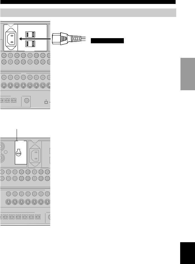
Connecting the power supply cord
AC IN
AC OUTLETS
AUDIO
CONNECTIONS
■ Connecting the AC power cord
Plug the power cord into the AC inlet after all other connections are complete, then plug the power cord into an AC wall outlet.
CAUTION
Do not use an AC power cord other than the one provided. Use of other power cords may result in fire or electrical shock.
|
|
|
IN(PLAY) OUT(REC) |
IN(PLAY) OUT(REC) |
IN(PL |
DTV/LD |
CBL |
SAT |
VCR 1 |
VCR 2 |
|
|
|
|
VIDEO |
|
|
DTV/LD |
CBL |
SAT |
IN VCR 1 OUT |
IN VCR 2 OUT |
IN |
|
|
DIGITAL OUTPUT |
|
D-R |
MD/TAPE |
DVR |
ZONE 2 |
|
|
|
S40 |
B |
C |
D |
(AUD |
|
|
|
|
|
|
OPTICAL |
COAXIAL |
VOLTAGE SELECTOR
VOLTAGE
SELECTOR
AC IN
+
R
–
ONT
A
A
AUDIO
UT(REC) |
IN(PLAY) OUT(REC) |
|
|
|
|
IN(PLAY) |
PE |
CD-R |
DVD |
DTV/LD |
CBL |
SAT |
V |
■ AC OUTLET(S) (SWITCHED)
U.K. and Australia models |
.............................. 1 OUTLET |
Korea model ............................................................... |
None |
Other models .................................................. |
2 OUTLETS |
Use the outlet(s) to connect the power cords from your other components to this unit. Power to the AC OUTLET(S) is turned on and off using STANDBY/ON (or SYSTEM POWER and STANDBY). The outlet(s) supply power to any connected component whenever this unit is turned on. The maximum power (total power consumption of components) that can be connected to the AC OUTLET(S) is:
Korea model ................................................................. |
N/A |
Other models ........................................................... |
120 W |
■ VOLTAGE SELECTOR
(General model only)
The VOLTAGE SELECTOR on the rear panel of this unit must be set to your local main voltage BEFORE plugging into the AC main supply. Voltages are 110/120/220/230240 V AC and 50/60 Hz.
■ Memory back-up
The memory back-up circuit prevents the stored data from being lost even if this unit is in the standby mode. However, if the power cord is disconnected from the AC wall outlet, or the power supply is cut for more than one week, the stored data will be lost.
|
|
|
|
|
|
|
VIDEO |
S1/S2 |
1–MONITOR OUT–2 |
DVD |
DTV/LD |
CBL |
SAT |
IN VC |
|
|
|
|
|
|
DIGITAL OUTPUT |
||
CBL |
SAT |
DVR |
|
CD-R MD/TAPE |
DVR |
ZO |
|
8 |
9 |
0 |
A |
B |
C |
D |
|
|
|
|
|
|
|
OPTICAL |
CO |
(General model)
PREPARATION
English
27
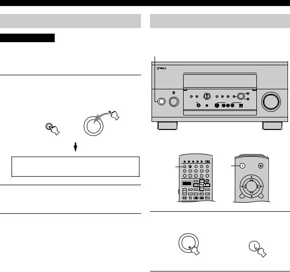
CONNECTIONS |
|
Speaker impedance setting |
Turning on the power |
CAUTION |
When all connections are complete, turn on this unit’s |
||||
power. |
|
|
|
|
|
|
|
|
|
|
|
If you are using 6-ohm speakers, set the impedance to 6 |
1 |
|
|
|
|
ohms as follows before turning on the power. |
|
|
|
|
|
|
|
|
|
|
|
Be sure this unit is in the standby mode. |
|
|
|
|
|
1 On the front panel, while holding down |
|
|
|
|
|
SPEAKERS A, press STANDBY/ON. |
PURE DIRECT |
|
REC OUT/ZONE 2 |
|
VOLUME |
|
|
|
SOURCE/REMOTE |
|
MULTI JOG BALANCE |
“SP Imp. Set” appears on the front panel display for a |
2CH/MULTI CH |
SPEAKERS |
|
MULTI CH |
DSP |
|
|
INPUT MODE INPUT |
EFFECT |
||
|
|
|
STRAIGHT PROGRAM |
||
|
INPUT SELECTOR |
|
|
|
|
|
|
|
|
|
TONE |
|
|
|
|
|
CONTROL |
few seconds, then “Minimum 8ohms” appears. |
STANDBY |
|
|
|
|
|
/ON |
SILENT |
OPTIMIZER |
|
VIDEO AUX |
|
|
|
MIC |
|
|
SPEAKERS |
|
|
|
|
|
A |
|
|
|
|
|
STANDBY |
|
|
|
|
|
/ON |
|
|
|
|
|
ASPAImp.ASet
MinimumA8ohms
2Press SPEAKERS A or SPEAKERS B to select the impedance of your speakers.
MACRO
|
TRANSMIT |
RE-NAME CLEAR LEARN |
MACRO |
OFF ON |
SYSTEM |
STANDBY |
|
|
|
|
|
|
|
POWER |
|
1 |
SYSTEM |
STANDBY |
V-AUX |
TUNER |
PHONO |
1 |
|
POWER |
|
||||||
CABLE |
SAT |
MD/TAPE |
CD-R |
CD |
|
||
|
DTV/LD |
VCR 1 |
VCR 2 |
DVR |
DVD |
|
|
|
|
|
PURE DIRECT |
|
MULTI CH IN |
|
|
|
|
|
TITLE |
|
|
|
|
|
|
|
|
ENTER |
|
|
ENTER |
|
SOURCE |
|
TOP |
|
EXIT |
|
|
|
INPUT MODE |
|
|
|
|||
|
|
DISPLAY |
MENU |
|
SOUND |
|
|
|
SELECT |
SEARCH |
– CHAPTER + |
|
|
||
|
POWER |
REC |
STOP |
PAUSE |
PLAY |
|
|
|
|
|
|
|
|
TOP |
EXIT |
10KEY AMP STEREO |
HALL |
CHURCH |
JAZZ |
You can select either 6 ohms or 8 ohms.
3Press STANDBY/ON to exit the setting.
This unit is set to the standby mode.
1Press STANDBY/ON (SYSTEM POWER on the remote controls) to turn on this unit’s power.
|
SYSTEM |
|
POWER |
STANDBY |
or |
/ON |
|
Front panel |
Remote controls |
2Turn on the video monitor connected to this unit.
28
 Loading...