


OWNER’S MANUAL
DT125R
3MB-28199-E7

INTRODUCTION
EAU00001 |
|
|
Welcome to the Yamaha world of motorcycling! |
1 |
|
As the owner of a DT125R, you are benefiting from Yamaha’s vast experience in and newest tech- |
2 |
|
nology for the design and the manufacture of high-quality products, which have earned Yamaha a |
|
|
reputation for dependability. |
|
|
Please take the time to read this manual thoroughly, so as to enjoy all your DT125R’s advantages. |
4 |
|
The owner's manual does not only instruct you in how to operate, inspect and maintain your motorcy- |
||
|
||
cle, but also in how to safeguard yourself and others from trouble and injury. |
5 |
|
|
||
In addition, the many tips given in this manual will help to keep your motorcycle in the best possible |
|
|
condition. If you have any further questions, do not hesitate to contact your Yamaha dealer. |
6 |
|
The Yamaha team wishes you many safe and pleasant rides. So, remember to put safety first! |
7 |
|
|
8 |
|
|
9 |
IMPORTANT MANUAL INFORMATION
EAU00005
Particularly important information is distinguished in this manual by the following notations:
1 Q
2
The Safety Alert Symbol means ATTENTION! BECOME ALERT! YOUR SAFETY IS INVOLVED!
|
w Failure to follow WARNING instructions |
could result in severe injury or death |
to the |
|
3 |
|
motorcycle operator, a bystander or a person inspecting or repairing the motorcycle. |
||
4 |
|
|
|
|
|
|
|
|
|
cC |
A CAUTION indicates special precautions that must be taken to avoid damage to |
|||
|
|
the motorcycle. |
||
5 |
|
|
|
|
|
|
|
|
|
6 |
NOTE: |
A NOTE provides key information to make procedures easier or clearer. |
||
|
|
|
|
|
|
|
|
|
|
7 |
|
|
|
|
|
NOTE: |
|
|
|
|
|
|
|
|
88This manual should be considered a permanent part of this motorcycle and should remain with it even if the motorcycle is subsequently sold.
98Yamaha continually seeks advancements in product design and quality. Therefore, while this manual contains the most current product information available at the time of printing, there may be minor discrepancies between your motorcycle and this manual. If there is any question concerning this manual, please consult your Yamaha dealer.

|
|
IMPORTANT MANUAL INFORMATION |
|
||
|
|
|
|
|
|
|
|
EW000002 |
|
||
w |
|
|
|
||
PLEASE READ THIS MANUAL CAREFULLY AND COMPLETELY BEFORE OPERATING |
1 |
||||
THIS MOTORCYCLE. |
|||||
|
|
|
|
|
2 |
|
|
|
|
|
|
4
5
6
7
8
9
1
2
3
4
5
6
7
8
9
EAU03337
DT125R
OWNER’S MANUAL
© 2000 by Yamaha Motor Co., Ltd. 1st Edition, December 2000
All rights reserved.
Any reprinting or unauthorized use without the written permission of Yamaha Motor Co., Ltd.
is expressly prohibited. Printed in Japan.

EAU00009
TABLE OF CONTENTS
1 |
..................GIVE SAFETY THE RIGHT OF WAY |
1-1 |
|
|
DESCRIPTION |
2-1 |
|
2 |
|||
Left view |
2-1 |
||
|
|||
|
Right view ......................................................... |
2-2 |
|
|
Controls/Instruments......................................... |
2-3 |
|
|
INSTRUMENT AND CONTROL FUNCTIONS |
3-1 |
|
3 |
|||
|
Main switch |
3-1 |
|
|
|||
|
Indicator lights................................................... |
3-1 |
|
|
Oil level indicator circuit check.......................... |
3-2 |
|
|
Speedometer .................................................... |
3-3 |
|
|
Tachometer....................................................... |
3-3 |
|
|
Engine temperature gauge ............................... |
3-4 |
|
|
Handlebar switches .......................................... |
3-4 |
|
|
Clutch lever....................................................... |
3-5 |
|
|
Shift pedal......................................................... |
3-5 |
|
|
Front brake lever............................................... |
3-6 |
|
|
Rear brake pedal .............................................. |
3-6 |
|
|
Fuel tank cap .................................................... |
3-6 |
|
|
Fuel (except for Switzerland and Austria)......... |
3-7 |
|
|
Fuel (for Switzerland and Austria) .................... |
3-7 |
|
|
Catalyzer (for Switzerland and Austria) ............ |
3-8 |
|
|
Two-stroke engine oil........................................ |
3-9 |
|
|
Fuel cock .......................................................... |
3-9 |
|
|
Starter (choke) “1”......................................... |
3-10 |
|
Kick starter...................................................... |
3-11 |
|
|
Steering lock ................................................... |
3-11 |
|
|
Seat ................................................................ |
3-12 |
|
|
Helmet holder ................................................. |
3-12 |
|
|
Rear shock absorber adjustment.................... |
3-13 |
|
|
Rear carrier..................................................... |
3-14 |
|
|
Note on handling of the Yamaha Energy |
|
|
|
Induction System (Y.E.I.S.)............................. |
3-14 |
|
|
Y.P.V.S. |
|
|
|
(Yamaha Power Valve System)...................... |
3-15 |
|
|
Sidestand........................................................ |
3-15 |
|
|
Sidestand switch operation check .................. |
3-16 |
|
|
PRE-OPERATION CHECKS |
4-1 |
|
4 |
|||
Pre-operation check list .................................... |
4-1 |
||
|
|||
|
OPERATION AND IMPORTANT RIDING |
|
|
5 |
|
||
POINTS................................................................ |
5-1 |
||
|
|||
|
Starting the engine............................................ |
5-1 |
|
|
Starting a warm engine..................................... |
5-3 |
|
|
Shifting.............................................................. |
5-4 |
|
|
Recommended shift points |
|
|
|
(for Switzerland only) ........................................ |
5-4 |
|
|
Tips for reducing fuel consumption................... |
5-5 |
|
|
Engine break-in................................................. |
5-5 |
|
|
Parking.............................................................. |
5-6 |
1
2
3
4
5
6
7
8
9

1
2
3
4
5
6
7
8
9
TABLE OF CONTENTS
6 |
PERIODIC MAINTENANCE AND MINOR |
|
|
REPAIR |
6-1 |
|
||
|
Tool kit .............................................................. |
6-1 |
|
Periodic maintenance and lubrication chart...... |
6-3 |
|
Cowling removal and installation ...................... |
6-6 |
|
Cowling A.......................................................... |
6-6 |
|
Cowling B.......................................................... |
6-7 |
|
Cowling C ......................................................... |
6-8 |
|
Panel removal and installation.......................... |
6-8 |
|
Panel D ............................................................. |
6-9 |
|
Panel E ............................................................. |
6-9 |
|
Spark plug....................................................... |
6-10 |
|
Transmission oil.............................................. |
6-11 |
|
Cooling system ............................................... |
6-12 |
|
Changing the coolant...................................... |
6-13 |
|
Air filter............................................................ |
6-15 |
|
Carburetor adjustment .................................... |
6-16 |
|
Idle speed adjustment..................................... |
6-17 |
|
Throttle cable free play adjustment................. |
6-17 |
|
Tires................................................................ |
6-18 |
|
Wheels............................................................ |
6-20 |
|
Clutch lever free play adjustment ................... |
6-21 |
|
Front brake lever free play adjustment ........... |
6-21 |
|
Rear brake pedal height adjustment............... |
6-22 |
|
Brake light switch adjustment ......................... |
6-23 |
|
Checking the front and rear brake pads ......... |
6-23 |
Inspecting the brake fluid level ....................... |
6-24 |
Brake fluid replacement .................................. |
6-25 |
Drive chain slack check .................................. |
6-25 |
Drive chain slack adjustment .......................... |
6-26 |
Drive chain lubrication .................................... |
6-26 |
Cable inspection and lubrication..................... |
6-27 |
Throttle cable and grip lubrication................... |
6-27 |
Autolube pump adjustment ............................. |
6-28 |
Brake and shift pedal lubrication..................... |
6-28 |
Brake and clutch lever lubrication................... |
6-28 |
Sidestand lubrication ...................................... |
6-29 |
Front fork inspection ....................................... |
6-29 |
Steering inspection ......................................... |
6-30 |
Wheel bearings............................................... |
6-30 |
Battery ............................................................ |
6-31 |
Fuse replacement ........................................... |
6-33 |
Headlight bulb replacement ............................ |
6-33 |
Turn signal light bulb replacement.................. |
6-35 |
Tail/brake light bulb replacement.................... |
6-35 |
Supporting the motorcycle .............................. |
6-36 |
Front wheel removal ....................................... |
6-36 |
Front wheel installation ................................... |
6-37 |
Rear wheel removal........................................ |
6-38 |
Rear wheel installation.................................... |
6-39 |
Troubleshooting .............................................. |
6-39 |
Troubleshooting chart ..................................... |
6-40 |

TABLE OF CONTENTS
7 |
MOTORCYCLE CARE AND STORAGE |
.............7-1 |
|
|
..................................................................Care |
7-1 |
|
|
Storage ............................................................. |
7-4 |
|
|
SPECIFICATIONS |
8-1 |
|
8 |
|||
How to use the conversion table....................... |
8-5 |
||
|
|||
|
CONSUMER INFORMATION |
9-1 |
|
9 |
|||
Identification number records |
9-1 |
||
|
|||
|
Key identification number ................................. |
9-1 |
|
|
Vehicle identification number............................ |
9-1 |
|
|
Model label ....................................................... |
9-2 |
1
2
3
4
5
6
7
8
9

1
2
3
4
5
6
7
8
9
EAU00021
QGIVE SAFETY THE RIGHT OF WAY
Motorcycles are fascinating vehicles, which can give you an unsurpassed feeling of power and freedom. However, they also impose certain limits, which you must accept; even the best motorcycle does not ignore the laws of physics.
Regular care and maintenance are essential for preserving your motorcycle’s value and operating condition. Moreover, what is true for the motorcycle is also true for the rider: good performance depends on being in good shape. Riding under the influence of medication, drugs and alcohol is, of course, out of the question. Motorcycle riders - more than car drivers - must always be at their mental and physical best. Under the influence of even small amounts of alcohol, there is a tendency to take dangerous risks.
Protective clothing is as essential for the motorcycle rider as seat belts are for car drivers and passengers. Always wear a complete motorcycle suit (whether made of leather or tear-resistant synthetic materials with protectors), sturdy boots, motorcycle gloves and a properly fitting helmet. Optimum protective wear, however, should not encourage carelessness. Though full-coverage helmets and suits, in particular, create an illusion of total safety and protection, motorcyclists will always be vulnerable. Riders who lack critical self-control run the risk of going too fast and are apt to take chances. This is even more dangerous in wet weather. The good motorcyclist rides safely, predictably and defensively - avoiding all dangers, including those caused by others.
Enjoy your ride!
1-1

1
2
3
4
5
6
7
8
EAU00026
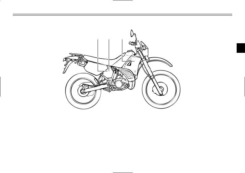
DESCRIPTION
Left view
1 |
2 3 |
4 |
5 |
6 |
10 |
9 |
8 |
7 |
|
1. |
Headlight |
(page 6-33) |
7. |
Starter (choke) |
(page 3-10) |
9 |
2. |
Radiator cap |
(page 6-13) |
8. |
Shift pedal |
(page 3-5, 5-4) |
|
3. |
Fuel cock |
(page 3-9) |
9. |
Y.E.I.S. |
(page 3-14) |
|
4. |
Air filter |
(page 6-15) |
10. |
Y.P.V.S. |
(page 3-15) |
|
5. |
Coolant reservoir tank |
(page 6-13) |
|
|
|
|
6. |
Helmet holder |
(page 3-12) |
|
|
|
2-1
DESCRIPTION
Right view
11 12 13
|
|
|
|
|
|
|
|
|
|
|
|
|
|
|
|
|
|
|
|
|
|
|
15 |
14 |
|||
11. |
Tool kit |
(page 6-1) |
|
|
|
|
12. |
Fuse |
(page 6-33) |
|
|
|
|
13. |
Engine oil tank |
(page 3-9) |
|
|
|
|
14. |
Rear brake pedal |
(page 3-6, 6-22) |
|
|
|
|
15. |
Rear shock absorber spring |
|
|
|
|
|
|
preload adjusting nut |
(page 3-13) |
|
|
|
|
1
2
3
4
5
6
7
8
9
2-2
DESCRIPTION
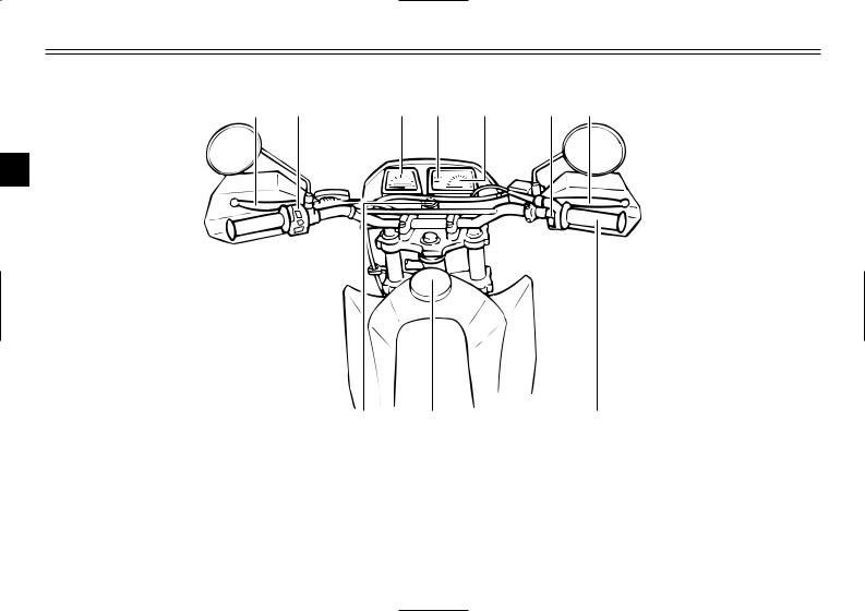
Controls/Instruments
16 |
17 |
18 |
19 |
20 |
21 |
22 |
1
2 |
|
|
|
3 |
|
|
|
4 |
|
|
|
5 |
|
|
|
6 |
|
|
|
7 |
|
|
|
8 |
25 |
24 |
23 |
9 |
(page 3-5, 6-21) |
21. |
Right handlebar switches |
16. Clutch lever |
|||
17. Left handlebar switches |
(page 3-4) |
22. |
Front brake lever |
18. Speedometer |
(page 3-3) |
23. |
Throttle grip |
19. Coolant temperature gauge |
(page 3-4) |
24. |
Fuel tank cap |
20. Tachometer |
(page 3-3) |
25. |
Main switch |
(page 3-5) (page 3-6, 6-27)
(page 6-17, 6-27) (page 3-6)
(page 3-1)
2-3
EAU00027
INSTRUMENT AND CONTROL FUNCTIONS
ON |
OFF |
EAU00028
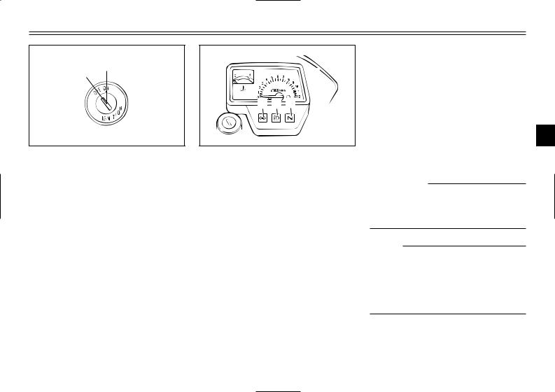
Main switch
The main switch controls the ignition and lighting systems. Its operation is described below.
EAU00036
ON
Electrical circuits are switched on. The engine can be started. The key cannot be removed in this position.
EAU00038
OFF
All electrical circuits are switched off. The key can be removed in this position.

 4
4
1 2 3
1.Turn indicator light “5”
2.High beam indicator light “&”
3.Neutral indicator light “N”
4.Oil level indicator light “7”
EAU00056
Indicator lights
EAU00057
Turn indicator light “ 5”
This indicator flashes when the turn switch is moved to the left or right.
EAU00061
Neutral indicator light “N”
This indicator comes on when the transmission is in neutral.
EAU00063
High beam indicator light “ &”
This indicator comes on when the headlight high beam is used.
EAU01313
Oil level indicator light “ 7”
This indicator comes on when the oil level is low. This light circuit can be checked by the procedure on page 3- 2.
EC000000
cC
Do not run the motorcycle until you know it has sufficient engine oil.
NOTE
Even if the oil is filled to the specified level, the indicator light may flicker when riding on a slope or during sudden acceleration or deceleration, but this is normal.
1
2
3
4
5
6
7
8
9
3-1
1
2
3
4
5
6
7
8
9
INSTRUMENT AND CONTROL FUNCTIONS
EAU00075
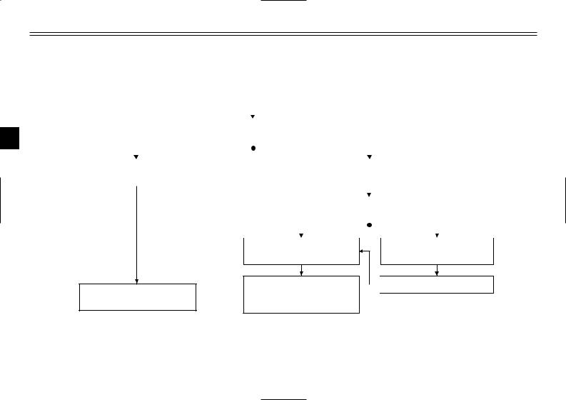
Oil level indicator circuit check
|
|
Turn the main switch to “ON”. |
|
|
|
|
|
|
|||||
|
|
|
|
|
|
|
|
|
|
|
|
|
|
|
|
|
|
|
|
|
|
|
|
|
|
|
|
|
|
Put the transmission in neutral. |
|
|
|
|
|
|
|||||
|
|
|
|
|
|
|
|
|
|
|
|
|
|
|
|
|
|
|
|
|
|
|
|
|
|
|
|
|
|
|
|
|
|
|
|
|
|
|
|
|
|
Oil level indicator light |
|
|
|
|
|
Oil level indicator light |
|
|
|||||
does not come on. |
|
|
|
|
|
comes on. |
|
|
|||||
|
|
|
|
|
|
|
|
|
|
|
|
|
|
|
|
|
|
|
|
|
Shift into gear. |
|
|
||||
|
|
|
|
|
|
|
|
|
|
|
|
|
|
|
|
|
|
|
|
|
|
|
|
|
|
|
|
|
|
|
|
|
|
|
|
|
|
|
|
|
|
Ask a Yamaha dealer to inspect electrical circuit.
Oil level indicator light does not come on.
Engine oil level and electrical circuit are OK. Go ahead with riding.
Oil level indicator light comes on.
 Supply engine oil.
3-2
INSTRUMENT AND CONTROL FUNCTIONS
1 |
2 |
|
|
4 |
3 |
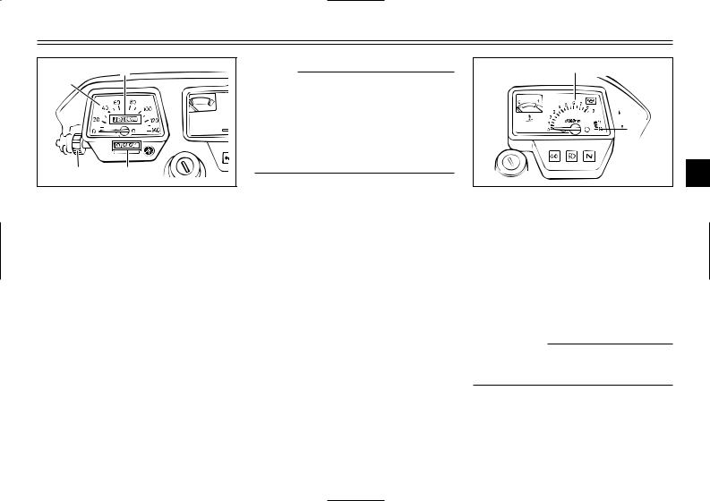
1.Speedometer
2.Odometer
3.Trip odometer
4.Reset knob
EAU01087
Speedometer
The speedometer shows riding speed. This speedometer is equipped with an odometer and trip odometer. The trip odometer can be reset to “0” with the reset knob. Use the trip odometer to estimate how far you can ride on a tank of fuel. This information will enable you to plan fuel stops in the future.
NOTE:
(for German model equipped with speed limiter only)
This motorcycle is equipped with a speed limiter which prevents it from exceeding a top speed of 80 km/h.
1


 2
2
1.Tachometer
2.Red zone
EAU00102
Tachometer
This model is equipped with a tachometer so the rider can monitor the engine speed and keep it within the ideal power range.
EC000003
cC
Do not operate in the red zone. Red zone: 10,500 r/min and above
1
2
3
4
5
6
7
8
9
3-3

1
2
3
4
5
6
7
8
9
INSTRUMENT AND CONTROL FUNCTIONS
1

 2
2
1.Coolant temperature gauge
2.Red zone
EAU01652
Coolant temperature gauge
This gauge indicates the coolant temperature when the main switch is on. The engine operating temperature will vary with changes in weather and engine load. If the needle points to the red zone or higher, stop your motorcycle and let the engine cool. (See page 6-13 for details.)
EC000002
cC
When the engine is overheated, do not continue riding.
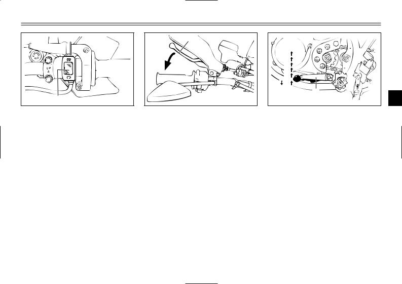
1 2 |
|
4 |
3 |
1.Lights switch
2.Dimmer switch
3.Turn signal switch
4.Horn switch “*”
EAU00118
Handlebar switches
EAU00134
Lights switch
Turning the light switch to “'”, turns on the auxiliary light, meter lights and taillight. Turning the light switch to “:”, turns the headlight on also.
EAU00121
Dimmer switch
Turn the switch to “&” for the high beam and to “%” for the low beam.
EAU00127
Turn signal switch
To signal a right-hand turn, push the switch to “6”. To signal a left-hand turn, push the switch to “4”. Once the switch is released it will return to the center position. To cancel the signal, push the switch in after it has returned to the center position.
EAU00129
Horn switch “ *”
Press the switch to sound the horn.
3-4
INSTRUMENT AND CONTROL FUNCTIONS
1 |
1. Engine stop switch
EAU00138
Engine stop switch
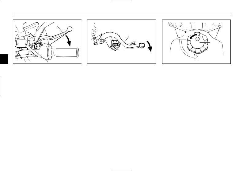
The engine stop switch is a safety device for use in an emergency such as when the motorcycle overturns or if trouble occurs in the throttle system. Turn the switch to “#” to start the engine. In case of emergency, turn the switch to “$” to stop the engine.
1. Clutch lever
EAU00155
Clutch lever
The clutch lever is located on the left handlebar. Pull the clutch lever to the handlebar to disengage the clutch, and release the lever to engage the clutch. The lever should be pulled rapidly and released slowly for smooth clutch operation.
6
5
4
3
2
N


1
1
1. Shift pedal N. Neutral
EAU00157
Shift pedal
This motorcycle is equipped with a constant-mesh 6-speed transmission. The shift pedal is located on the left side of the engine and is used in combination with the clutch when shifting.
1
2
3
4
5
6
7
8
9
3-5
INSTRUMENT AND CONTROL FUNCTIONS
1 |
2 |
3 |
1. Front brake lever
4
EAU00158
Front brake lever
5The front brake lever is located on the right handlebar. Pull it toward the
6handlebar to apply the front brake.
7
8
9
1. Rear brake pedal
EAU00162
Rear brake pedal
The rear brake pedal is on the right side of the motorcycle. Press down on the brake pedal to apply the rear brake.
 2
2
1
3
1. Fuel tank cap
2. Unlock
3. Open
EAU00177
Fuel tank cap
To open
Insert the key and turn it 1/4 turn counterclockwise. Turn the cap 1/3 turn counterclockwise and remove it from the tank.
To close
Put the cap in the filler neck and turn it 1/3 turn clockwise. Lock the cap by turning the key 1/4 turn clockwise, and remove the key.
3-6
INSTRUMENT AND CONTROL FUNCTIONS
NOTE:
The tank cap cannot be reinstalled unless it is unlocked. The key must remain in the cap until the cap is properly installed and locked onto the fuel tank.
EW000023
w
Be sure the cap is properly installed and locked in place before riding the motorcycle.
1


 2
2
1.Filler tube
2.Fuel level
EAU01183
Fuel
(except for Switzerland and Austria)
Make sure there is sufficient fuel in the tank. Fill the fuel tank to the bottom of the filler tube as shown in the illustration.
EW000130
w
Do not overfill the fuel tank. Avoid spilling fuel on the hot engine. Do not fill the fuel tank above the bottom of the filler tube or it may overflow when the fuel heats up later and expands.
|
|
2 |
|
|
|
|
1 |
4 |
3 |
1 |
2 |
|
|||
|
|
|
3 |
1. |
Filler tube |
4 |
2. |
Filling nozzle |
3.Leaf valve
4.Fuel level
EAU01184 5
Fuel
(for Switzerland and Austria) |
6 |
Make sure there is sufficient fuel in
the tank. When refueling, be sure to
7
insert the filling nozzle into the filler hole and fill the tank to the bottom of
the filler tube as shown in the illustra- 8 tion.
9
3-7
1
2
3
4
5
6
7
8
9
INSTRUMENT AND CONTROL FUNCTIONS
EW000130
w
Do not overfill the fuel tank. Avoid spilling fuel on the hot engine. Do not fill the fuel tank above the bottom of the filler tube or it may overflow when the fuel heats up later and expands.
EAU00185
cC
Always wipe off spilled fuel immediately with a dry and clean soft cloth. Fuel may deteriorate painted surfaces or plastic parts.
EAU00191
Recommended fuel:
Regular unleaded gasoline with a research octane number of 91 or higher.
Fuel tank capacity: Total:
10.0 L Reserve:
1.8 L
NOTE:
If knocking or pinging occurs, use a different brand of gasoline or higher octane grade.
EAU01084
Catalyzer
(for Switzerland and Austria)
This motorcycle is equipped with a catalytic converter in the exhaust chamber.
EW000128
w
The exhaust system is hot during and directly after engine operation. Make sure the exhaust system has cooled down before making any adjustment to or lubricating the motorcycle.
3-8
INSTRUMENT AND CONTROL FUNCTIONS
EC000114
cC
The following must be observed to prevent a fire hazard or other damages.
8Use only unleaded gasoline. Use of leaded gasoline will cause unrepairable damage to the catalytic converter.
8Never park this motorcycle in an area that would cause a fire hazard such as grass or other materials that may easily burn.
8Do not allow the engine to idle for very long.
1

 2
2

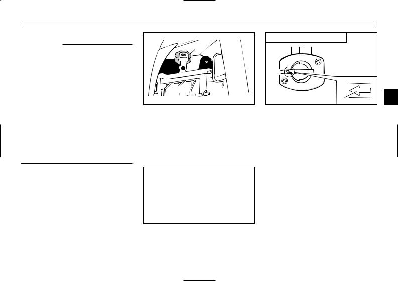
1.Oil tank cap
2.Stopper
EAU02956
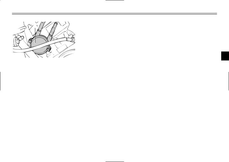
Two-stroke engine oil
Make sure there is sufficient twostroke engine oil in the oil tank. Add the recommended oil as necessary.
Recommended oil: Yamalube 2 or 2-stroke
engine oil (JASO FC grade or ISO EG-C, EG-D grade)
Oil quantity: 1.2 L
OFF: closed position |
|
RES |
1 |
OFF |
2 |
|
|
ON |
|
1 |
3 |
1. Arrow mark positioned “OFF”
4
EAU03050
Fuel cock
The fuel cock supplies fuel from the |
5 |
tank to the carburetor while filtering it |
|
also. |
6 |
The fuel cock has three positions: |
|
|
OFF |
7 |
|
|
||
With the lever in this position, fuel will |
8 |
|
not flow. Always return the lever to |
||
|
||
this position when the engine is not |
9 |
|
running. |
||
|
3-9
INSTRUMENT AND CONTROL FUNCTIONS
|
ON: normal position |
|
1 |
RES |
|
|
|
|
|
OFF |
|
2 |
|
|
3 |
ON |
1 |
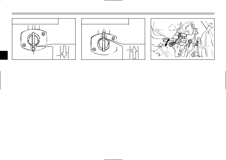
1. Arrow mark positioned “ON”
4
|
ON |
|
5 |
With the lever in this position, fuel |
|
flows to the carburetor. Normal riding |
||
|
||
6 |
is done with the lever in this position. |
|
|
7
8
RES: reserve position |
|
RES |
|
OFF |
|
UEL |
1 |
ON |
|
1. Arrow mark positioned “RES”
RES
This indicates reserve. If you run out of fuel while riding, move the lever to this position. Fill the tank at the first opportunity. Be sure to set the lever back to “ON” after refueling!
|
|
a |
|
b |
1 |
|
|
|
1. |
Starter (choke) “1” |
|
|
|
EAU02976 |
Starter (choke) “ 1” |
||
Starting a cold engine requires a richer air-fuel mixture. A separate starter circuit supplies this mixture.
Move in direction a to turn on the starter (choke).
Move in direction b to turn off the starter (choke).
9
3-10
INSTRUMENT AND CONTROL FUNCTIONS
1 |
1. Kick starter
EAU00212
Kick starter
Rotate the kick starter away from the engine. Push the starter down lightly with your foot until the gears engage, then kick smoothly and forcefully to start the engine. This model has a primary-coupled kick starter so the engine can be started in any gear if the clutch is disengaged. However, shifting to neutral before starting is recommended.
1 |
1. Steering lock
EAU02934
Steering lock
To lock the steering
Turn the handlebars all the way to the right and open the steering lock cover.
Insert the key and turn it 1/8 turn counterclockwise. Then, push the key in while turning the handlebars slightly to the left and turn the key 1/8 turn clockwise.
Check that the steering is locked, remove the key and close the lock cover.
To unlock the steering
Insert the key, push it in and turn it 1/8 turn counterclockwise so that it moves out. Then, release and remove the key.
1
2
3
4
5
6
7
8
9
3-11

INSTRUMENT AND CONTROL FUNCTIONS
|
1 |
|
1 |
|
|
2 |
|
|
3 |
|
|
4 |
1. Bolt (×2) |
|
EAU01648 |
||
|
||
5 |
Seat |
|
To remove |
1. Remove panels D and E. (See
6page 6-9 for panel removal and installation procedures.)
72. Remove the seat bolts and lift the seat upward.
8
9
To install
1.Insert the projections on the front of the seat into the holders, then tighten the seat bolts.
2.Install the panels.
NOTE:
Make sure that the seat is securely fitted.
1 |
1. Open
EAU00261
Helmet holder
To open the helmet holder, insert the key in the lock and turn it as shown. To lock the helmet holder, turn the key to its original position.
EW000030
w
Never ride with a helmet in the helmet holder. The helmet may hit objects, causing loss of control and possibly an accident.
3-12
INSTRUMENT AND CONTROL FUNCTIONS
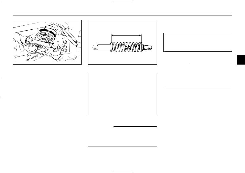
b |
“A” |
|
|
|
a |
|
2 |
|
1 |
1.Locknut
2.Adjusting nut
EAU01650
Rear shock absorber adjustment
This shock absorber is equipped with a spring preload adjuster. Adjust spring preload as follows.
1.Loosen the locknut.
2.Turn the adjusting nut in direction a to increase spring preload and in direction b to decrease spring preload. The spring preload is determined by the spring set length.
Shortening the spring set length increases spring preload, lengthening the spring set length decreases spring preload.
Spring preload:
Minimum (soft):
Distance “A” = 235 mm
Standard:
Distance “A” = 230 mm
Maximum (hard):
Distance “A” = 220 mm
EC000015
cC
Never attempt to turn an adjuster beyond the maximum or minimum setting.
3.Tighten the locknut to the specified torque.
Tightening torque: Locknut:
55 Nm (5.5 m0kg)
EC000018
cC
Always tighten the locknut against the spring adjusting nut and tighten the locknut to the specified torque.
1
2
3
4
5
6
7
8
9
3-13
1
2
3
4
5
6
7
8
9
INSTRUMENT AND CONTROL FUNCTIONS
EAU00315
w
This shock absorber contains highly pressurized nitrogen gas. Read and understand the following information before handling the shock absorber. The manufacturer cannot be held responsible for property damage or personal injury that may result from improper handling.
8Do not tamper with or attempt to open the cylinder assembly.
8Do not subject the shock absorber to an open flame or other high heat source. This may cause the unit to explode due to excessive gas pressure.
8Do not deform or damage the cylinder in any way. Cylinder damage will result in poor damping performance.
8Take your shock absorber to a Yamaha dealer for any service.
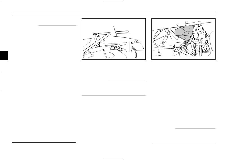
1 |
1. Rear carrier
EAU00320
Rear carrier
EW000032
w
Do not exceed the load limit of 2 kg.
1 |
2 |
1.Air chamber
2.Hose
EAU00325
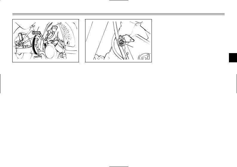
Note on handling of the Yamaha Energy Induction System (Y.E.I.S.)
Handle the air chamber and hose with special care. Improper installation or damaged parts will result in poor performance. Replace any cracked or damaged parts immediately. No modification of this system in any form can be made.
EC000022
cC
Never attempt to modify the Yamaha Energy Induction System.
3-14
INSTRUMENT AND CONTROL FUNCTIONS
|
|
|
|
|
EC000023 |
|
1 |
|
|
cC |
|
|
|
|
The Y.P.V.S. was set at the |
||
|
|
|
|
||
|
|
|
|
Yamaha factory after many tests. If |
|
|
|
|
|
the settings are disturbed by |
|
|
|
|
|
someone without sufficient techni- |
|
|
|
|
|
cal knowledge, poor engine perfor- |
|
|
|
|
|
mance and damage may result. |
|
|
|
|
|
|
|
|
|
|
|
|
|
1. Y.P.V.S. |
|
|
|
The Y.P.V.S. operation can be heard |
|
|
|
|
|
||
|
|
EAU00326 |
|||
Y.P.V.S. (Yamaha Power |
in the following instances: |
||
Valve System) |
8When the main switch is turned |
||
The Y.P.V.S. is a vital part of the |
on and the engine is started. |
||
8When the engine stalls while the |
|||
engine and requires very sophisticat- |
|||
ed adjustment. Adjustment should be |
main switch is on. |
||
|
EC000024 |
||
left to a Yamaha dealer who has the |
|
||
cC |
|
||
professional knowledge and experi- |
If the Y.P.V.S. does not operate, |
||
ence to do so. |
|||
ask a Yamaha dealer to inspect the |
|||
|
|||
|
vehicle. |
||
|
|
|
|
EAU00330
Sidestand
This model is equipped with an ignition circuit cut-off system. The motorcycle must not be ridden when the sidestand is down. The sidestand is located on the left side of the frame. (Refer to page 5-1 for an explanation of this system.)
1
2
3
4
5
6
7
8
9
3-15
 Loading...