


GUITAR PRE-AMPLIFIER
PRÉ AMPLIFICATEUR DE GUITARE GITARREN-VORVERSTÄ RKER
Owner’s Manual
Mode d’emploi
Bedienungsanleitung
GAIN
FCC INFORMATION (U.S.A.) |
||
1. IMPORTANT NOTICE: DO NOT MODIFY THIS UNIT! |
regulations does not guarantee that interference will not occur in |
|
This product, when installed as indicated in the instructions con- |
all installations. If this product is found to be the source of inter- |
|
ference, which can be determined by turning the unit “OFF” and |
||
tained in this manual, meets FCC requirements. Modifications not |
||
“ON”, please try to eliminate the problem by using one of the |
||
expressly approved by Yamaha may void your authority, granted |
||
following measures: |
||
by the FCC, to use the product. |
||
Relocate either this product or the device that is being affected by |
||
2. IMPORTANT: When connecting this product to accessories and/ |
||
or another product use only high quality shielded cables. Cable/s |
the interference. |
|
Utilize power outlets that are on different branch (circuit breaker |
||
supplied with this product MUST be used. Follow all installation |
||
instructions. Failure to follow instructions could void your FCC |
or fuse) circuits or install AC line filter/s. |
|
authorization to use this product in the USA. |
In the case of radio or TV interference, relocate/reorient the an- |
|
3. NOTE: This product has been tested and found to comply with |
tenna. If the antenna lead-in is 300 ohm ribbon lead, change the |
|
the requirements listed in FCC Regulations, Part 15 for Class “B” |
lead-in to co-axial type cable. |
|
digital devices. Compliance with these requirements provides a |
If these corrective measures do not produce satisfactory results, |
|
reasonable level of assurance that your use of this product in a |
please contact the local retailer authorized to distribute this type |
|
residential environment will not result in harmful interference with |
of product. If you can not locate the appropriate retailer, please |
|
other electronic devices. This equipment generates/uses radio |
contact Yamaha Corporation of America, Electronic Service Divi- |
|
frequencies and, if not installed and used according to the instruc- |
sion, 6600 Orangethorpe Ave, Buena Park, CA90620 |
|
tions found in the users manual, may cause interference harmful |
The above statements apply ONLY to those products distributed |
|
to the operation of other electronic devices. Compliance with FCC |
||
by Yamaha Corporation of America or its subsidiaries. |
||
|
||
|
|
|
* This applies only to products distributed by YAMAHA CORPORATION OF AMERICA. |
|
|
ADVARSEL!
Lithiumbatteri— Eksplosionsfare ved fejlagtig håndtering. Udskiftning må kun ske med batteri af samme fabrikat og type. Levér det brugte batteri tilbage til leverandø ren.
VARNING
Explosionsfara vid felaktigt batteribyte. Använd samma batterityp eller en ekvivalent typ som rekommenderas av apparattillverkaren. Kassera använt batteri enlight fabrikantens instruktion.
VAROITUS
Paristo voi räjähtää , jos se on virheellisesti asennettu. Vaihda paristo ainoastaan laitevalmistajan suosittelemaan tyyppiin.
Hävitä käytetty paristo valmistajan ohjeiden mukaisesti.
NEDERLAND / NETHERLAND
•Dit apparaat bevat een lithium batterij voor geheugen back-up.
•This apparatus contains a lithium battery for memory back-up.
•Raadpleeg uw leverancier over de verwijdering van de batterij op het moment dat u het apparaat ann het einde van de levensduur afdankt of de volgende Yamaha Service Afdeiing:
Yamaha Music Nederland Service Afdeiing
Kanaalweg 18-G, 3526 KL UTRECHT
Tel. 030-2828425
•For the removal of the battery at the moment of the disposal at the end of the service life please consult your retailer or Yamaha
Service Center as follows:
Yamaha Music Nederland Service Center
Address : Kanaalweg 18-G, 3526 KL UTRECHT
Tel : 030-2828425
•Gooi de batterij niet weg, maar lever hem in als KCA.
•Do not throw away the battery. Instead, hand it in as small chemical waste.
IMPORTANT NOTICE FOR THE UNITED KINGDOM
Connecting the Plug and Cord
IMPORTANT. The wires in this mains lead are coloured in accordance with the following code:
BLUE |
: |
NEUTRAL |
BROWN |
: |
LIVE |
As the colours of the wires in the mains lead of this apparatus may not correspond with the coloured makings identifying the terminals in your plug proceed as follows:
The wire which is coloured BLUE must be connected to the terminal which is marked with the letter N or coloured BLACK.
The wire which is coloured BROWN must be connected to the terminal which is marked with the letter L or coloured RED.
Making sure that neither core is connected to the earth terminal of the three pin plug.
The exclamation point within the equilateral triangle is intended to alert the user to the presence of important operating and maintenance (servicing) instructions in the literature accompanying the product.
The lightning flash with arrowhead symbol, within the equilateral triangle, is intended to alert the user to the presence of uninsulated “dangerous voltage” within the product’s enclosure that may be of sufficient magnitude to constitute a risk of electrical shock.
• This applies only to products distributed by Yamaha-Kemble Music (U.K.) Ltd.

IMPORTANT SAFETY INSTRUCTIONS
INFORMATION RELATING TO PERSONAL INJURY, ELECTRICAL SHOCK, AND FIRE HAZARD POSSIBILITIES HAS BEEN INCLUDED IN THIS LIST.
WARNING- When using any electrical or electronic product, basic precautions should always be followed. These precautions include, but are not limited to, the following:
1. Read all Safety Instructions, Installation Instructions, Special Message Section items, and any Assembly Instructions found in this manual BEFORE making any connections, including connection to the main supply.
2. Do not attempt to service this product beyond that described in the user-maintenance instructions. All other servicing should be referred to qualified service personnel.
3. Main Power Supply Verification: Yamaha products are manufactured specifically for the supply voltage in the area where they are to be sold. If you should move, or if any doubt exists about the supply voltage in your area, please contact your dealer for supply voltage verification and (if applicable) instructions. The required supply voltage is printed on the name plate. For name plate location, please refer to the graphic found in the Special Message Section of this manual.
4. DANGER-Grounding Instructions: This product must be grounded and therefore has been equipped with a three pin attachment plug. If this product should malfunction, the ground pin provides a path of low resistance for electrical current, reducing the risk of electrical shock. If your wall socket will not accommodate this type plug, contact an electrician to have the outlet replaced in accordance with local electrical codes. Do NOT modify the plug or change the plug to a different type!
5. WARNING: Do not place this product or any other objects on the power cord or place it in a position where anyone could walk on, trip over, or roll anything over power or connecting cords of any kind. The use of an extension cord is not recommended! If you must use an extension cord, the minimum wire size for a 25' cord (or less) is 18 AWG. NOTE: The smaller the AWG number, the larger the current handling capacity. For longer extension cords, consult a local electrician.
6. Ventilation: Electronic products, unless specifically designed for enclosed installations, should be placed in locations that do not interfere with proper ventilation. If instructions for enclosed installations are not provided, it must be assumed that unobstructed ventilation is required.
7. Temperature considerations: Electronic products should be installed in locations that do not seriously contribute to their operating temperature. Placement of this product close to heat sources such as; radiators, heat registers etc., should be avoided.
8. This product was NOT designed for use in wet/damp locations and should not be used near water or exposed to rain. Examples of wet /damp locations are; near a swimming pool, spa, tub, sink, or wet basement.
9. This product should be used only with the components supplied or; a cart ,rack, or stand that is recommended by the manufacturer. If a cart, rack, or stand is used, please observe all safety markings and instructions that accompany the accessory product.
10. The power supply cord (plug) should be disconnected from the outlet when electronic products are to be left unused for extended periods of time. Cords should also be disconnected when there is a high probability of lightening and/or electrical storm activity.
11. Care should be taken that objects do not fall and liquids are not spilled into the enclosure through any openings that may exist.
12. Electrical/electronic products should be serviced by a qualified service person when:
a.The power supply cord has been damaged; or
b.Objects have fallen, been inserted, or liquids have been spilled into the enclosure through openings; or
c.The product has been exposed to rain; or
d.The product does not operate, exhibits a marked change in performance; or
e.The product has been dropped, or the enclosure of the product has been damaged.
13.This product, either alone or in combination with an amplifier and headphones or speaker/s, may be capable of producing sound levels that could cause permanent hearing loss. DO NOT operate for a long period of time at a high volume level or at a level that is uncomfortable. If you experience any hearing loss or ringing in the ears, you should consult an audiologist.
IMPORTANT: The louder the sound, the shorter the time period before damage occurs.
14. Some Yamaha products may have benches and/or accessory mounting fixtures that are either supplied as a part of the product or as optional accessories. Some of these items are designed to be dealer assembled or installed. Please make sure that benches are stable and any optional fixtures (where applicable) are well secured BEFORE using. Benches supplied by Yamaha are designed for seating only. No other uses are recommended.
PLEASE KEEP THIS MANUAL
92-469-3 |
1 |
Thank you for purchasing the Yamaha DG-1000 Guitar Pre-amplifier.
From its initial conception, the DG-1000 has been entirely developed by Yamaha. The DG-1000 delivers powerful tube amp sounds and offers stability that can not be found in other tube amplifiers. The DG-1000 reproduces 8 preset amp types that can then be custom tailored by the user. A total of 128 sound settings can be stored in internal memory, that can be freely recalled using the panel buttons or a MIDI foot controller.
Easy to use controls and a high level of quality will help supply you with a wide variety of tonal colors. To get the best results and longest life out of your DG1000, we recommend that you carefully read this manual. Also, keep this manual in a safe place for future reference.
■ Specifications
A/D Converter |
20 bit + 5 bit Floating |
|||||
D/A Converter |
20 bit |
|||||
Sampling Frequency |
48kHz |
|||||
Memory |
128 |
|
|
|
|
|
Input Impedance |
1MΩ |
(Input Jack) |
||||
Output Impedance |
1kΩ |
(Output Jack) |
||||
Controllers |
|
|
|
|
|
|
Analog |
TRIM, OUTPUT |
|||||
Digital |
GAIN, MASTER, TREBLE, HIGH MID, |
|||||
|
LOW MID, BASS, PRESENCE, AMP |
|||||
|
SELECT (LEAD1, LEAD2, DRIVE1, |
|||||
|
DRIVE2, CRUNCH1, CRUNCH2, |
|||||
|
|
|
|
|||
|
CLEAN1, CLEAN2), |
|
, |
|
, STORE, |
|
|
RECALL, MIDI |
|||||
Display |
AMP SELECT display LED x 8, |
|||||
|
MODE display LED x 3, |
|||||
|
7 Segment LED x 2 Place |
|||||
Indicator |
TRIM level display LED (green) |
|||||
|
TRIM clip display LED (red) |
|||||
Power Requirements |
UL • CSA : AC 120 V |
|||||
|
SEMKO • BS : AC 230 V |
|||||
Power Consumption |
20 Watts |
|||||
Size (W x H x D) |
480 x 89 x 275 mm ( 18.9” x 3.5” x 10.8”) |
|||||
Weight |
6.0 kg (13 lbs. 4 oz) |
|||||
* Specifications and design may change without notice.
CONTENTS |
|
The Panel Controls .............................................. |
3 |
Connecting the DG-1000 ..................................... |
4 |
■ Connecting Procedure ........................................... |
4 |
How to use the DG-1000 ...................................... |
4 |
■ First, acquire sound ............................................... |
4 |
■ Set the TRIM level .................................................. |
4 |
■ Set the OUTPUT level ............................................ |
4 |
■ Sound Setting ........................................................ |
4 |
Store and Recall ................................................... |
5 |
■ Store Settings ........................................................ |
5 |
■ Recall Memory ....................................................... |
5 |
MIDI Operations (MIDI Mode) .............................. |
6 |
MIDI Implementation Chart ............................... |
17 |
About the Backup Battery
A backup battery (lithium battery) is used to keep internal data (settings) from being lost, even when the power cord is unplugged.
Internal data will be lost when battery power is depleted, so it is recommended that data be stored to an external data recorder such as the Yamaha MIDI Data Filer MDF2 (→ pg. 6), or keep records of settings in memo form. The average battery life span is about 3 years. When replacement becomes necessary contact the music store where the unit was purchased, or a qualified service representative, to perform the replacement.
•Do not attempt to replace the backup battery by yourself.
•Keep the backup battery out of reach of children.
•“E6” appears in the display when the battery becomes depleted.
Internal data may be lost.
•Data may be lost if the unit is improperly handled or if repairs are performed.
2
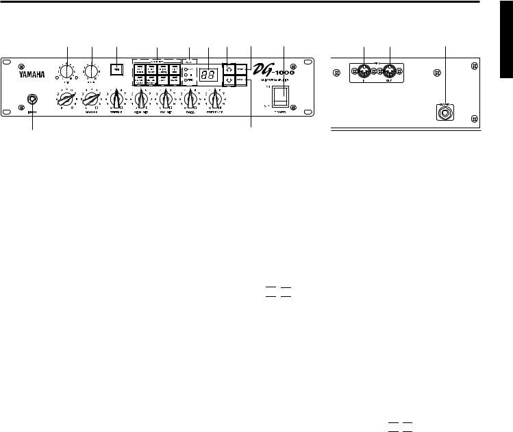
The Panel Controls
■ Front Panel |
■ Rear Panel |
w |
e |
u |
i |
o !0 !1 !2 |
!4 |
!6 !7 |
!5 |
GAIN
|
|
|
|
|
|
|
!3 |
|
|
|
|
|
|
|
|
||
q r t |
y |
|||||||
|
||||||||
q Input Jack (INPUT) |
|
|
|
• EDIT (Edit mode) |
||||
Connect the guitar to this jack.
* Switch the power OFF before connecting the guitar.
Automatically enters this mode when tone control or amp select settings are changed. (→ pg. 4)
• MIDI (MIDI Mode)
w Trim Control (TRIM)
Matches the guitar output level to the pre-amp’s input level. (→ pg. 4)
* TRIM level settings are not stored in memory.
e Output Level Control (OUTPUT)
Controls the output level of the OUTPUT jack on the back panel. Matches the output level to the amp’s input level. (→ pg.4)
* Output level settings are not stored in memory.
r Gain Volume (GAIN)
Controls the amount of distortion.
*No sound will be produced if GAIN is set to 0, even if the MASTER volume t is turned up.
t Master Volume (MASTER)
Controls the overall volume of GAIN and tone controls settings.
MIDI functions are edited in this mode.
Press the MIDI button u to enter the MIDI mode. (→ pg. 6)
!0Display
Displays Memory Numbers, Program Change Numbers, MIDI Channel, etc.
!1

 /
/ 

 Buttons
Increases or decreases the memory number by 1. Also, increases or decreases values by 1, or switches the MIDI mode ON/OFF when in the MIDI mode. Values change continuously when the button is pressed and held.
!2STORE Button (STORE)
Press this button to save current sound settings to internal memory. (→ pg. 5) Also, used to carry out bulk dump functions in the MIDI mode. (→ pg. 6)
y Tone Controls
(TREBLE, HIGH MID, LOW MID, BASS, PRESENCE)
Controls the levels of their respective frequencies.
u MIDI Button
Press this button to edit settings in the MIDI mode. (→ pg. 6)
iAmp Select Button/Amp Select Display (LEAD 1, 2/DRIVE 1,2/CRUNCH 1,2/CLEAN 1,2)
Selects one of the 8 preset amp types. The currently selected amp type is shown on the display. (→ pg. 4)
Also acts as the MIDI function switch when in the MIDI mode. (→ pg. 6)
*When the amp select button is pressed, knobs r – y will return to their preset positions (GAIN & MASTER = 7, Tone Controls all = 5).
o Mode Display Lamp (PLAY/EDIT/MIDI)
Displays the DG-1000’s currently selected mode.
• PLAY (Play Mode):
Automatically enters this mode when a memory number is recalled, and when the power is switched on. (→ pg. 4)
!3RECALL Button (RECALL)
Recalls settings from memory. Use the 

 /
/ 

 buttons to select a memory number (01 – 128), then press the RECALL button to recall those settings from memory. (→ pg. 5)
!4POWER Switch (POWER)
The power switch for the DG-1000.
* Set the OUTPUT Volume e to 0 before turning the POWER ON/OFF.
!5OUTPUT Jack (OUTPUT)
Connect to the power amp (or guitar amp). (→ pg. 4)
!6MIDI IN Jack
Connected to a MIDI Foot Controller’s MIDI OUT jack, the DG-1000 can be controlled by an external foot controller. (→ pg. 6)
!7MIDI OUT/THRU Jack
Connect to the MIDI IN jack of a device that can save MIDI data. Data stored in the DG-1000’s memory can be saved to an external MIDI device (MIDI Data Filer, etc.). (→ pg. 5)
Also, sends MIDI data, received by the MIDI IN jack !6, to an external device when MIDI Merge is set to ON. (→ pg. 6)
3
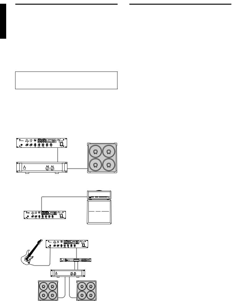
Connecting the DG-1000 How to use the DG-1000
To set up a guitar amp system, connect the DG-1000 to a power amp and speaker.
As you know, power amps and speakers all have their own special characteristics. So the sound’s character will change according to the type of devices used. The combined result of each device’s character, room temperature, room humidity, and a variety of other factors, determines the guitar’s sound. The purpose of the DG-1000 is to create sound by faithfully reproducing the dynamic range and tone nuance of the guitar as well as preserving the characteristics of the power amp, speakers, etc. The DG-1000 will surely provide you with the means to create your own personal sound.
■ Connecting Procedure
Make sure that the power is switched OFF on the DG1000 and the power amp (guitar amp) before making any connections.
1.Connect the OUTPUT jack on the rear panel of the DG-1000 to the INPUT jack on the power amp using a cable.
*Choose a cable that matches the required jack standard. The DG-
1000’s OUTPUT jack is monaural.
2.Connect the power amp’s speaker output (SPEAKER, etc.) to a speaker.
*Use a speaker that matches the power characteristics of the amp (power capacity, system impedance).
DG-1000
Speaker
GAIN
OUTPUT
Power Amp |
INPUT |
SPEAKER |
● Connecting the DG-1000 to a guitar amp is also possible
Guitar Amp
RETURN or INPUT (RETURN is better)
OUTPUT
DG-1000
● Add a stereo effector to the system
DG-1000
|
GAIN |
INPUT |
OUTPUT |
Stereo Effect
2 CH Power Amp
Speaker |
Speaker |
Once the amp and speaker has been properly set up, try getting some
sound out of the system.
■ First, acquire sound
1.With the DG-1000 and power amp (guitar amp) power switched OFF, connect the guitar to the INPUT jack on the front panel.
2.With the OUTPUT knob set to “0”, switch the power ON.
3.A short time after the power has been switched ON, the DG1000’s internal relay will produce a small “Click” sound. Once the sound is heard, set the power amp’s (guitar amp’s) volume to “0” and switch the power ON on the power amp (guitar amp).
4.At first, set the DG-1000’s TRIM and OUTPUT levels to “5” and strum the guitar. Then adjust the power amp’s volume level.
5.Once you have sound, set the TRIM and OUTPUT levels as described in the following procedures.
■ Set the TRIM level
The TRIM level is used to set the output level of the guitar to an optimum level for the DG-1000’s INPUT jack. Depending on the TRIM level subtle picking nuances and the attack of a strong strum can be realized.
An improperly adjusted trim level will result in noise, feedback and a cut up sound.
*Output levels vary according to the type of guitar used. If a different guitar is used, adjust the trim level to match the guitar.
*Even to create distortion, make sure that the TRIM level is properly adjusted, and use the GAIN control to create distortion.
1.Set the guitar’s volume to its maximum level and strum it powerfully. Begin to adjust the TRIM level.
An optimum level is achieved when the Green LED is lit.
2.Continue adjusting the TRIM knob until the Red LED lights. Set the TRIM level to 10 if the Red LED does not light. If the Red LED lights, lower the TRIM level until the Green LED lights.
■ Set the OUTPUT level
Use the OUTPUT knob to set the DG-1000’s required OUTPUT level.
■ Sound Setting
Choose one of the DG-1000’s 8 preset amp types, then use the GAIN+MASTER, and Tone Controls to shape the sound.
1.With one of the AMP SELECT buttons choose an amp type.The LED will light on the selected amp type button.
2.Use the GAIN, MASTER, and the 5 Tone Controls to shape the sound.
*When an AMP SELECT button is pressed, all knobs (Except TRIM and GAIN) will return to their preset positions (GAIN & MASTER = 7, Tone Controls all = 5). To save edited settings, refer to “Store Settings” on the next page.
4
 Loading...