


GUITAR AMPLIFIER AMPLIFICATEUR DE GUITARE GITARRENVERSTÄRKER
Owner’s Manual
Mode d’emploi
Bedienungsanleitung
FCC INFORMATION (U.S.A.)
1. IMPORTANT NOTICE: DO NOT MODIFY THIS UNIT! |
tions does not guarantee that interference will not occur in all |
|
This product, when installed as indicated in the instructions |
installations. If this product is found to be the source of inter- |
|
ference, which can be determined by turning the unit “OFF” |
||
contained in this manual, meets FCC requirements. Modifica- |
||
and “ON”, please try to eliminate the problem by using one of |
||
tions not expressly approved by Yamaha may void your au- |
||
the following measures: |
||
thority, granted by the FCC, to use the product. |
||
Relocate either this product or the device that is being af- |
||
2. IMPORTANT: When connecting this product to accessories |
||
and/or another product use only high quality shielded cables. |
fected by the interference. |
|
Utilize power outlets that are on different branch (circuit |
||
Cable/s supplied with this product MUST be used. Follow all |
||
installation instructions. Failure to follow instructions could |
breaker or fuse) circuits or install AC line filter/s. |
|
void your FCC authorization to use this product in the USA. |
In the case of radio or TV interference, relocate/reorient the |
|
3. NOTE: This product has been tested and found to comply |
antenna. If the antenna lead-in is 300 ohm ribbon lead, |
|
with the requirements listed in FCC Regulations, Part 15 for |
change the lead-in to co-axial type cable. |
|
Class “B” digital devices. Compliance with these require- |
If these corrective measures do not produce satisfactory |
|
ments provides a reasonable level of assurance that your use |
results, please contact the local retailer authorized to distrib- |
|
of this product in a residential environment will not result in |
ute this type of product. If you can not locate the appropriate |
|
harmful interference with other electronic devices. This |
retailer, please contact Yamaha Corporation of America, |
|
equipment generates/uses radio frequencies and, if not in- |
Electronic Service Division, 6600 Orangethorpe Ave, Buena |
|
stalled and used according to the instructions found in the |
Park, CA90620 |
|
users manual, may cause interference harmful to the opera- |
The above statements apply ONLY to those products distrib- |
|
tion of other electronic devices. Compliance with FCC regula- |
||
uted by Yamaha Corporation of America or its subsidiaries. |
||
|
* This applies only to products distributed by YAMAHA CORPORATION OF AMERICA.
ADVARSEL!
Lithiumbatteri—Eksplosionsfare ved fejlagtig håndtering.
Udskiftning må kun ske med batteri af samme fabrikat og type. Levér det brugte batteri tilbage til leverandøren.
VARNING
Explosionsfara vid felaktigt batteribyte. Använd samma batterityp eller en ekvivalent typ som rekommenderas av apparattillverkaren. Kassera använt batteri enlight fabrikantens instruktion.
VAROITUS
Paristo voi räjähtää, jos se on virheellisesti asennettu. Vaihda paristo ainoastaan laitevalmistajan suosittelemaan tyyppiin. Hävitä käytetty paristo valmistajan ohjeiden mukaisesti.
NEDERLAND / NETHERLAND
•Dit apparaat bevat een lithium batterij voor geheugen back-up.
•This apparatus contains a lithium battery for memory back-up.
•Raadpleeg uw leverancier over de verwijdering van de batterij op het moment dat u het apparaat ann het einde van de levensduur afdankt of de volgende Yamaha Service Afdeiing:
Yamaha Music Nederland Service Afdeiing
Kanaalweg 18-G, 3526 KL UTRECHT
Tel. 030-2828425
•For the removal of the battery at the moment of the disposal at the end of the service life please consult your retailer or Yamaha
Service Center as follows:
Yamaha Music Nederland Service Center
Address : Kanaalweg 18-G, 3526 KL UTRECHT
Tel : 030-2828425
•Gooi de batterij niet weg, maar lever hem in als KCA.
•Do not throw away the battery. Instead, hand it in as small chemical waste.
IMPORTANT NOTICE FOR THE UNITED KINGDOM
Connecting the Plug and Cord
WARNING: THIS APPARATUS MUST BE EARTHED IMPORTANT. The wires in this mains lead are coloured in accordance with the following code:
GREEN-AND-YELLOW : EARTH
BLUE |
: NEUTRAL |
BROWN |
: LIVE |
As the colours of the wires in the mains lead of this apparatus may not correspond with the coloured markings identifying the terminals in your plug proceed as follows:
The wire which is coloured GREEN-and-YELLOW must be connected to the terminal in the plug which is marked by the letter E or by the safety earth symbol or colored GREEN or GREEN-and-YELLOW.
The wire which is coloured BLUE must be connected to the terminal which is marked with the letter N or coloured BLACK.
The wire which is coloured BROWN must be connected to the terminal which is marked with the letter L or coloured RED.
• This applies only to products distributed by Yamaha-Kemble Music (U.K.) Ltd.
The exclamation point within the equilateral triangle is intended to alert the user to the presence of important operating and maintenance (servicing) instructions in the literature accompanying the product.
The lightning flash with arrowhead symbol, within the equilateral triangle, is intended to alert the user to the presence of uninsulated “dangerous voltage” within the product’s enclosure that may be of sufficient magnitude to constitute a risk of electrical shock.
2

IMPORTANT SAFETY INSTRUCTIONS
INFORMATION RELATING TO PERSONAL INJURY, ELECTRICAL SHOCK, AND FIRE HAZARD POSSIBILITIES HAS BEEN INCLUDED IN THIS LIST.
WARNING- When using any electrical or electronic product, basic precautions should always be followed. These precautions include, but are not limited to, the following:
1. Read all Safety Instructions, Installation Instructions, Special Message Section items, and any Assembly Instructions found in this manual BEFORE making any connections, including connection to the main supply.
2. Do not attempt to service this product beyond that described in the user-maintenance instructions. All other servicing should be referred to qualified service personnel.
3. Main Power Supply Verification: Yamaha products are manufactured specifically for the supply voltage in the area where they are to be sold. If you should move, or if any doubt exists about the supply voltage in your area, please contact your dealer for supply voltage verification and (if applicable) instructions. The required supply voltage is printed on the name plate. For name plate location, please refer to the graphic found in the Special Message Section of this manual.
4. DANGER-Grounding Instructions: This product must be grounded and therefore has been equipped with a three pin attachment plug. If this product should malfunction, the ground pin provides a path of low resistance for electrical current, reducing the risk of electrical shock. If your wall socket will not accommodate this type plug, contact an electrician to have the outlet replaced in accordance with local electrical codes. Do NOT modify the plug or change the plug to a different type!
5. WARNING: Do not place this product or any other objects on the power cord or place it in a position where anyone could walk on, trip over, or roll anything over power or connecting cords of any kind. The use of an extension cord is not recommended! If you must use an extension cord, the minimum wire size for a 25' cord (or less) is 18 AWG. NOTE: The smaller the AWG number, the larger the current handling capacity. For longer extension cords, consult a local electrician.
6. Ventilation: Electronic products, unless specifically designed for enclosed installations, should be placed in locations that do not interfere with proper ventilation. If instructions for enclosed installations are not provided, it must be assumed that unobstructed ventilation is required.
7. Temperature considerations: Electronic products should be installed in locations that do not seriously contribute to their operating temperature. Placement of this product close to heat sources such as; radiators, heat registers etc., should be avoided.
8. This product was NOT designed for use in wet/damp locations and should not be used near water or exposed to rain. Examples of wet /damp locations are; near a swimming pool, spa, tub, sink, or wet basement.
9. This product should be used only with the components supplied or; a cart ,rack, or stand that is recommended by the manufacturer. If a cart, rack, or stand is used, please observe all safety markings and instructions that accompany the accessory product.
10. The power supply cord (plug) should be disconnected from the outlet when electronic products are to be left unused for extended periods of time. Cords should also be disconnected when there is a high probability of lightening and/or electrical storm activity.
11. Care should be taken that objects do not fall and liquids are not spilled into the enclosure through any openings that may exist.
12. Electrical/electronic products should be serviced by a qualified service person when:
a.The power supply cord has been damaged; or
b.Objects have fallen, been inserted, or liquids have been spilled into the enclosure through openings; or
c.The product has been exposed to rain; or
d.The product does not operate, exhibits a marked change in performance; or
e.The product has been dropped, or the enclosure of the product has been damaged.
13.This product, either alone or in combination with an amplifier and headphones or speaker/s, may be capable of producing sound levels that could cause permanent hearing loss. DO NOT operate for a long period of time at a high volume level or at a level that is uncomfortable. If you experience any hearing loss or ringing in the ears, you should consult an audiologist.
IMPORTANT: The louder the sound, the shorter the time period before damage occurs.
14. Some Yamaha products may have benches and/or accessory mounting fixtures that are either supplied as a part of the product or as optional accessories. Some of these items are designed to be dealer assembled or installed. Please make sure that benches are stable and any optional fixtures (where applicable) are well secured BEFORE using. Benches supplied by Yamaha are designed for seating only. No other uses are recommended.
PLEASE KEEP THIS MANUAL
92-469-3 |
3 |

Thank you for purchasing the Yamaha DG100-212 Guitar Amplifier.
The DG100-212 Digital Guitar Amp was initially conceived and entirely developed by Yamaha. This digital guitar amp delivers powerful tube amp sounds and offers superior stability compared to other tube amplifiers. With eight different amp type settings from which to choose, the DG100-212 allows you to create a wide variety of original sounds.
A total of 128 sound settings can be stored in its internal memory and freely recalled using the panel buttons or a MIDI foot controller. Also, the DG100-212 is equipped with onboard digital reverb and digital tape echo which can be utilized to add sonic color to your tonal creations. Sound is output through two 30 centimeter Celestion “Vintage 30” speakers. A speaker simulator adds realistic speaker simulation to the line out signal.
Its high level of quality and easy to use controls will enable you to create a wide variety of tonal colors. To get the best results and longest life out of your DG100-212, we recommend that you carefully read this manual, and keep it in a safe place for future reference.
4

Contents
...................................................................Precautions |
5 |
.................................................................Utility Mode |
11 |
|
The Panel Controls ...................................................... |
6 |
■ Creating a Program Change Table ................................ |
11 |
|
■ Front Panel ...................................................................... |
6 |
■ Set the MIDI Receive Channel ...................................... |
11 |
|
■ Rear Panel ...................................................................... |
7 |
■ Set the MIDI Merge ....................................................... |
11 |
|
How to use the DG100-212 .......................................... |
8 |
■ MIDI Bulk Out ................................................................ |
11 |
|
■ First, achieve sound output |
8 |
■ MIDI Bulk In .................................................................. |
11 |
|
■ Speaker Simulator ON/OFF |
11 |
|
||
■ Adjust the TRIM level |
8 |
|
||
■ Set the Volume Pedal Position |
11 |
|
||
■ Sound Settings |
8 |
|
||
|
|
|
||
■ Reverb Settings ............................................................... |
8 |
Error Messages .......................................................... |
12 |
|
■ Tape Echo Settings ......................................................... |
8 |
Specifications ............................................................. |
12 |
|
Store and Recall ........................................................... |
9 |
MIDI Implementation Chart ....................................... |
31 |
|
■ Store Settings ................................................................. |
9 |
|
|
|
■ Recall Memory (Recall) .................................................. |
9 |
|
|
|
Easy to Use Functions............................................... |
10 |
|
|
|
■ Using MIDI to Recall Memory ....................................... |
10 |
|
|
|
■ Using MIDI to Control Volume ....................................... |
10 |
|
|
|
■ Using MIDI to Turn ON/OFF the Reverb |
|
|
|
|
and Tape Echo Effects .............................................. |
10 |
|
|
|
■ Speaker Simulator ........................................................ |
10 |
|
|
|
Precautions
●Avoid using your amplifier in the following locations to prevent possible damage:
•In direct sunlight or next to heating equipment.
•Extremely cold or hot locations.
•Locations exposed to high humidity or excessive dust.
•Locations subject to strong shocks or vibration.
●Before making any connections, make sure that the power on the DG100-212 and any external devices is switched OFF.
●To protect the speaker from possible damage, always set the OUTPUT knob to “0” before switching the power ON/OFF.
●When connecting a speaker to this unit make sure to turn OFF the power first.
●Do not apply excessive force to the switches and controls.
●Your Yamaha guitar amplifier is a precision musical instrument. Handle it with care and avoid dropping or bumping it.
●For safety, always remove the power plug from the AC wall outlet if there is any danger of lightning striking in your area.
●To prevent damage and possibly electrical shock, never open the case and tamper with the internal circuitry.
●Never use benzene, thinner or other volatile liquids for cleaning, as these chemicals may cause damage or discoloration to the finish. Always use a dry, soft cloth to wipe off dust and dirt.
About the Backup Battery
A backup battery (lithium battery) is used to keep internal data (settings) from being lost, even when the power cord is unplugged. Internal data will be lost when battery power is depleted, so it is recommended that data be stored to an external data recorder such as the Yamaha MIDI Data Filer MDF3 (→ page. 11), or keep records of settings in memo form. The average battery life span is about 3 years. When replacement becomes necessary contact the music store where the unit was purchased, or a qualified service representative, to perform the replacement.
•Do not attempt to replace the backup battery by yourself.
•Keep the backup battery out of reach of children.
•“E6” appears in the display when the battery becomes depleted. Internal data may be lost.
●Keep the amplifier away from neon signs or fluorescent lighting to prevent noise pickup.
•Data may be lost if the unit is improperly handled or if repairs are performed.
5
The Panel Controls
■ Front Panel
q w e r t |
y |
u |
i o !0 !3 !4!5 !7 |
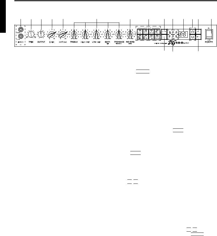
q Input Jack (INPUT HIGH, LOW)
Connect the guitar to this jack. Guitars with a high output level should be connected to the LOW jack. Those with low output levels should be connected to the HIGH jack.
* Switch the power OFF before connecting the guitar.
w Trim Control (TRIM)
Used to match the guitar’s output level to the pre-amp’s input level. (→
page 8.)
* TRIM level settings are not stored in memory.
e Output Level Control (OUTPUT)
Used to control the output volume of the power amp.
Sets the amount of output of sound created by the preamp’s GAIN,
MASTER, Tone Controls, etc. The volume is controlled without changing the tonal quality of the amp.
*Output level settings are not stored in memory.
*Has no affect on the level (volume) of the LINE OUT @4jack.
r Gain Volume (GAIN)
Used to control the amount of distortion.
*Sound is not produced if the GAIN is set to 0, even when the MASTER VOLUME t is turned up.
!1 !2 |
!6 |
o Reverb Type Select Button (REVERB)
!0ReverbType Display Lamp (SPRING, HALL, PLATE)
Press the 


 button to select the reverb type. The lamp corresponding to the selected reverb type will light. (→ page 8.)
!1Mode Select Button (MODE)
!2Mode Display Lamp (AMP/TAPE ECHO/UTIL.)
Displays the currently selected mode.
• AMP (Amp Mode)
Normal playing mode. All knobs and buttons on the panel function as marked. (Dual function knobs and buttons will function according to their upper indications.)
This mode is automatically engaged whenever a memory is recalled.
•TAPE ECHO (Tape Echo Mode) → page 8
The Tape Echo setting mode.
When in the Amp Mode, press the 


 button once and quickly release to enter the Tape Echo Mode.
•UTIL. (Utility Mode) → page 11
This mode is used to set MIDI functions and switch Speaker Simulation ON or OFF. When in the Amp Mode or Tape Echo Mode, press the 


 button and hold for about one second to enter the Utility
Mode.
t Master Volume (MASTER)
Used to control the overall volume of GAIN and tone control settings. It
also controls the output level of the preamp.
* Master level settings are stored in memory.
y Tone Controls
(TREBLE, HIGH MID, LOW MID, BASS, PRESENCE)
Used to control the levels of their respective frequencies.
When the Tape Echo Mode is engaged, the BASS and PRESENCE knobs are used to adjust the tape echo’s TIME and FEEDBACK settings. (→ page 8.)
u Reverb Volume (REVERB)
Used to control the amount of the reverb. (→ page 8.) When the Tape
Echo Mode is engaged, the REVERB knob is used to adjust the tape echo’s LEVEL setting. (→ page 8.)
i Amp Select Button/Amp Select Display
(LEAD 1, 2/DRIVE 1, 2/CRUNCH 1, 2/CLEAN 1, 2)
Used to select one of the eight preset amp types. The currently selected amp type is shown on the display. (→ page 8.)
When the Utility Mode is engaged, these switches are used to switch MIDI functions and the Speaker Simulator ON or OFF, etc. (→ page 11.)
*When the Amp Select button is pressed, knobs r – y return to their preset positions (GAIN and MASTER =7, Tone Controls all = 5). The position of the REVERB knob does not change.
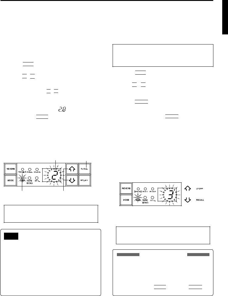
!3Display
Displays Memory Numbers, Program Change Numbers, the MIDI Channel, etc.
!4

 /
/ 

 Buttons
Increases or decreases the memory number by 1. Also, increases or decreases values by 1. In the Utility Mode increases/decreases values by 1 or sets the function ON/OFF. Values change continuously when the button is pressed and held.
!5Store Button (STORE)
Press this button to save current sound settings to internal memory. (→ page 9.) Also, used to carry out MIDI Bulk Out operations. (→ page 11.)
!6Recall Button (RECALL)
Recalls the settings stored in memory. Use the 

 /
/ 

 buttons to select a memory number (01 – 128), then press the


 button to recall those settings from memory. (→ page 9.)
!7Power Switch (POWER)
The power switch for the DG100-212.
*To protect the speakers from possible damage, always set the OUTPUT e volume to “0” before turning the power ON/OFF.
6
The Panel Controls
■ Rear Panel |
|
|
|
|
|
|
|
|
|
|
|
|
|
|
|
|
|
||
Before making any connections, make sure that the power on the DG100-212 |
|
|
|
||||||||||||||||
|
|
|
and any external devices is switched OFF. |
|
|
|
|
|
|
||||||||||
|
|
|
|
|
|
|
|
|
|
|
|
||||||||
!8 |
!9 |
@0 |
@1 |
@3 |
@2 |
@4 |
@5 |
|
|
|
|
||||||||
|
|
|
|
|
|
|
|
|
|
|
|
|
|
|
|
|
|
|
|
|
|
|
|
|
|
|
|
|
|
|
|
|
|
|
|
|
|
|
|
|
|
|
|
|
|
|
|
|
|
|
|
|
|
|
|
|
|
|
|
|
|
|
|
|
|
|
|
|
|
|
|
|
|
|
|
|
|
|
|
|
|
|
|
|
|
|
|
|
|
|
|
|
|
|
|
|
|
|
|
|
|
|
|
|
|
|
|
|
|
|
|
|
|
|
|
|
|
|
|
|
|
|
|
|
|
|
|
|
|
|
|
|
|
|
|
|
|
|
|
OUT |
IN |
DG100-212 internal speaker |
|
Mixer or additional amp |
or |
|
External Effector |
a speaker with an impedance |
|
|
of 4-8 Ω and can handle |
|
|
100W or more. |
|
|
MIDI IN |
MIDI OUT |
|
Store data from the |
88.8. . |
A MIDI Controller |
DG100-212’s |
|
can be used to |
internal memory to |
|
select memory and |
a MIDI device. |
|
control volume. |
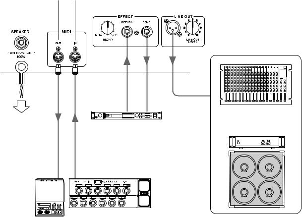
!8Speaker Jack (SPEAKER)
This jack connects the internal speaker to the internal amp. If necessary, you can disconnect the internal speaker and connect an external speaker to this jack.
If an external speaker is used, make sure that the speaker meets the following requirements.
• 100W or more power capacity, and an impedance of 4 – 8 Ω.
!9MIDI OUT Jack
Connect this jack to the MIDI IN jack of a device that can save MIDI data. The data stored in the DG100-212’s internal memory can then be transmitted to an external MIDI device for storage. (→ page 11: MIDI
Bulk Out)
Also, transmits MIDI data received by the MIDI IN jack @0, to an external device when MIDI Merge is set to ON. (→ page 11.)
An external effector can be inserted into the signal circuit between the
SEND/RETURN jacks.This allows further processing of the tone signal, created by the main unit, by an external effector. Use the BLEND knob to control the balance level between the external effector’s sound (EF-
FECT) and the sound created by the DG100-212 (DRY). Rotating the knob fully to the EFFECT position allows only the sound produced by the external effector to be heard. Rotating the knob fully to the DRY position allows only the internal sound created by the amp to be heard, without the added coloration of the external effector.
*Connecting a plug to the RETURN jack disconnects the internal circuit. The
signal returning from the effector enters the internal circuit here, where it goes on to the power amp → speaker. When the RETURN jack is not in use,
the BLEND knob will have no affect.
Also, the SEND jack can function as a pre-out jack, and the RETURN jack can function as a main-in jack.
@0MIDI IN Jack
Connect this jack to a MIDI Foot Controller’s MIDI OUT jack, and the external foot controller can be used to control the DG100-212. Memory selection, volume control, reverb and echo ON/OFF can all be controlled via an external foot controller. (→ page 10.)
Also, memory data stored in an external storage device can be re-loaded into the DG100-212’s internal memory. (→ page 11 MIDI Bulk In)
@1Effect Blend Control (EFFECT BLEND)
@2Effect Send Jack (EFFECT SEND)
@3Effect Return Jack (EFFECT RETURN)
@4Line Out Jack (LINE OUT)
@5Line Out Level Control (LINE OUT LEVEL)
The same signal that is sent to the speaker output jack !8, is also sent to the LINE OUT jack at a line level (+4dBm/600Ω). The amp also has an internal Speaker Simulator (can be switched ON/OFF → page 11.), the output level can be controlled with the LINE OUT LEVEL knob. The line signal can be sent to a mixer and can be used as an output jack to an external amp.
7
How to use the DG100-212
To protect the speaker from possible damage, always set the OUTPUT knob to “0” before switching the power ON/OFF.
■ First, achieve sound output
1.With the DG100-212’s power switched OFF, connect your guitar to the INPUT jack on the front panel.To start with, try using the LOW jack.
2.With the OUTPUT knob set to “0”, switch the power ON.
3.As a starting point, set the TRIM level to “5” and strum the guitar. Then, gradually raise the OUTPUT level.
4.Once you have sound output, proceed to set the TRIM level as described in the following section.
■ Adjust the TRIM level
The TRIM level allows you to set the output level of the guitar to an optimum level that matches the DG100-212’s INPUT jack. With a well adjusted TRIM level, subtle picking nuances and the attack of a strong strum can be clearly heard. An improperly adjusted trim level will result in noise, feedback, and/or a cut up sound.
*The output level between guitars does vary. Whenever you switch guitars, it will be necessary to readjust the trim level to match the guitar.
*HIGH and LOW input levels are different. Even if the same guitar is used, make sure the TRIM level is readjusted whenever a different input jack is used.
*Even when creating distortion, make sure that the TRIM level is properly adjusted, and use the GAIN control to produce distortion.
1.Set the guitar’s volume to its maximum level and powerfully strum the guitar. Begin to adjust the TRIM level.
An optimum level is achieved when the Green LED is lit.
2.Continue rotating the TRIM knob to the right, so long as the Red LED does not light. Set the TRIM level to 10 if the Red LED does not light.
*If the Red LED still does not light, lower the TRIM level, connect the guitar to the HIGH input jack and repeat the previous procedure.
■ Sound Settings
Choose one of the DG100-212’s eight preset amp types, then use the
GAIN+MASTER, and tone controls to shape the guitar’s sound.
1.Choose an amp type using one of the AMP SELECT buttons. The selected amp type button’s LED will light.
2.Use the GAIN, MASTER, and the five tone controls to shape the guitar’s sound.
HINT OUTPUT knob and MASTER knob
Turning either knob will change the volume. The MASTER knob controls the preamp’s master volume. This setting is stored in memory. The OUTPUT knob controls the power amp’s volume. This setting is not stored in memory. Volume levels for individual memory settings should be set with the MASTER knob. The speaker’s output level should be controlled with the OUTPUT knob.
*When an AMP SELECT button is pressed, all knobs (except TRIM, OUTPUT and REVERB) will return to their preset positions. (GAIN and MASTER = 7, all tone controls = 5. To save edited settings, refer to the “Store Settings” section on page 9.)
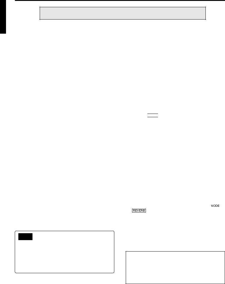
■ Reverb Settings
Three types of digital reverb are available in the DG100-212’s reverb section. Spring reverb, which realistically simulates the reverb found in vintage guitar amps, plate reverb, and hall reverb.
1.Press the REVERB button to select a reverb type. Each time
the REVERB button is pressed, the type will cycle through SPRING → HALL → PLATE settings. The lamp for the selected
reverb type will light.
2.Use the REVERB knob to adjust the amount of reverb.
*Reverb settings (type and REVERB knob settings) will remain in affect, even if the AMP SELECT button is pressed to change the amp type. When a different memory number is recalled, the reverb settings for that memory number will then be in affect.
■ Tape Echo Settings
The DG100-212’s internal digital tape echo can realistically simulate
the sound of a tape type echo machine.
1.Press the 


 button to enter the Tape Echo setting mode, the “TAPE ECHO” display lamp will light. At this time BASS, PRESENCE and REVERB knobs will automatically reset to “0”.
*If there are previously set tape echo settings in the selected memory, the knobs will rotate to the positions set in the memory.
2.Use the BASS, PRESENCE and REVERB knobs to adjust the amount of tape echo reverb.
• BASS (TIME: Echo Time)
Sets the amount of time between the sounding of the string and the echo sound (the amount of time it takes between one echo and the next). Rotate the knob to the right to increase the amount of time.
• PRESENCE (FEEDBACK)
Sets the length of time that the echo will repeat. Rotate the knob to the right to increase the length of time. Rotating the knob too much can result in uncontrollable feedback, please use caution.
• REVERB (LEVEL: Echo Level)
Sets the echo’s volume level.
3. When the setting procedure is complete, press the |
|
or |
button and the PLAY lamp will light.
The BASS, PRESENCE and REVERB knobs will revert to the settings that they were in prior to entering the tape echo setting mode.
*When in the Tape Echo Mode, knobs other than the BASS, PRESENCE and REVERB knobs, as well as the TRIM and OUTPUT knobs will not function.
*Tape echo settings will remain in affect, even if you press the AMP SELECT button to select another amp type. When you recall a different memory number, the tape echo settings for that memory number will then be in affect.
With the procedures on this page, you can create an original sound (settings), and along with the reverb and echo settings they can be stored in the DG100212’s internal memory for instant recall at anytime.The procedure for storing data in memory is explained on the next page.
8
Store and Recall
The DG100-212’s internal memory can hold up to 128 amp type and settings (GAIN, MASTER, Tone Control, Reverb and Tape Echo). Each setting (sound) can be recalled at any time. Motor drives in the knobs will automatically set the knobs to the corresponding positions. Create a sound and try storing it in memory.
■ Store Settings |
■ Recall Memory (Recall) |
1.Use the procedure on page 8 and create a sound using the eight preset amp types and control knobs on the front panel.
*Each of the Utility Mode’s settings cannot be stored in individual memory. When the power is switched OFF, each memory’s settings are stored in memory as common settings. When the power is turned ON, those settings are recalled.
2.Press the 


 button, the AMP or TAPE ECHO mode display lamp will light.
3.Using the 

 /
/ 

 buttons, select a memory number to which the settings will be saved.The memory number will flash in the
display.
*Press and hold either of the 

 /
/ 

 buttons makes memory numbers cycle rapidly.
*The third digit of the memory number (100 – 128) is represented by a dot between the two digits.
Example) 128 is displayed as →
4.Press and hold the 


 button for about one second, until “88.” appears on the display.
Release the button, the flashing memory number will then light indicating the setting is saved to memory.
*TRIM and OUTPUT settings cannot be stored in memory. Use the MASTER knob to set backing and soloing levels.
The memory number to be stored. |
|
Flashing → 88. .→ Lights |
Execute Store |
Sound settings stored in memory can easily be recalled by selecting a memory number.
When a memory is recalled, the current settings will be changed. If you want to keep the settings, use the Store operation, described on the left side of this page, to store settings to memory.
1.Press the 


 button, the AMP or TAPE ECHO mode display will light.
2.Use the 

 /
/ 

 buttons to select the memory number you want to recall. The memory number will appear on the display
(flashing).
3.Press the 


 button. The flashing memory number will light. Each of the knobs, and the Amp Select Display will change according to the data recalled from memory.
*Settings will not change until the 


 button is pushed.
*TRIM and OUTPUT knob settings will not change with the Recall operation.
*It takes anywhere from 1 – 10 seconds for the knobs to change to their set positions however, internal settings (sound) will change instantly.
*“E1” will appear on the display if the volume knob does not go to its assigned position, or the device does not recognize the recall command after 20 seconds has elapsed from the start of the recall operation. Continued use of the device in this condition may result in fire or electrical shock. Take the unit to the music dealer where you purchased it, or to the nearest Yamaha Service Center for repair.
The memory number to be recalled, shown on the display, goes from flashing to lit.
Lights |
|
Select the memory number. |
Data stored in memory (1 – 128) can be saved to an external MIDI storage device. Refer to page 11 for details.
HINT Some hints on storing memory numbers
When storing data to memory numbers, divide the memory numbers 1 – 128 into several groups.
Recalling memory numbers from these groups is much more convenient. For example:
•Create groups according to the amp type used (LEAD1, DRIVE 1, etc.).
•Create groups based on sound types (Distortion, Clean, etc.)
•Create groups based on live performance song lists.
•Create groups based on the type of guitar used (humbucker, etc.).
It is also a good idea to keep a chart handy listing the types of sounds are stored in memory numbers.
|
|
|
|
|
|
|
|
|
|
|
|
|
|
|
|
|
|
|
|
|
|
|
|
|
|
|
|
|
|
|
|
|
|
|
|
|
|
|
|
|
|
|
|
|
|
|
|
|
|
|
|
|
|
|
|
|
|
|
|
|
|
|
|
|
|
|
|
|
|
|
|
|
|
|
|
|
|
|
|
|
|
|
|
|
|
|
|
|
|
|
|
|
|
|
|
|
|
|
|
|
|
|
|
|
|
|
|
|
|
|
|
|
|
|
|
|
|
|
|
|
|
|
|
|
|
|
|
|
|
|
|
|
|
|
|
|
|
|
|
|
|
|
|
|
|
|
|
|
|
|
|
|
|
|
|
|
|
|
|
|
|
|
|
|
|
|
|
|
|
|
|
|
|
|
|
|
|
|
|
|
|
|
|
|
|
|
|
|
|
Execute Recall |
|||||
Lights |
|
|
|
|
|
|
|||||||
|
|
|
|
|
|
|
|
|
|
|
|
||
|
|
Select the memory number to be recalled. |
|||||||||||
A MIDI foot controller or other external MIDI device can be used to select and recall memory. Refer to the following page to page 10 for details.
Initialize the memory
Use the following operation to restore all of the internal memory (No. 1 – 128) settings to their original factory set condition (GAIN and MASTER = 7, all tone controls = 5). Any data that has been previously saved to memory will be lost so, please use caution.
[Operation]
While holding both the  button and the
  button, switch the power ON.
9
Easy to Use Functions
Using MIDI commands you can select memory numbers on the DG100-212, turn ON/OFF the reverb and tape echo effects, and control volume. A speaker simulator can also be applied to the line out signal.
What is MIDI? MIDI is the acronym for Musical Instruments Digital Interface. MIDI is a world-wide standard communication interface that allows MIDI compatible musical instruments, computers and other MIDI devices to share musical information and control one another regardless of instrument type or maker.
■ Using MIDI to Recall Memory
Program changes sent from a Yamaha MIDI Foot Controller MFC10, etc., or an external MIDI device can be used to recall settings in the DG100-212’s memory.
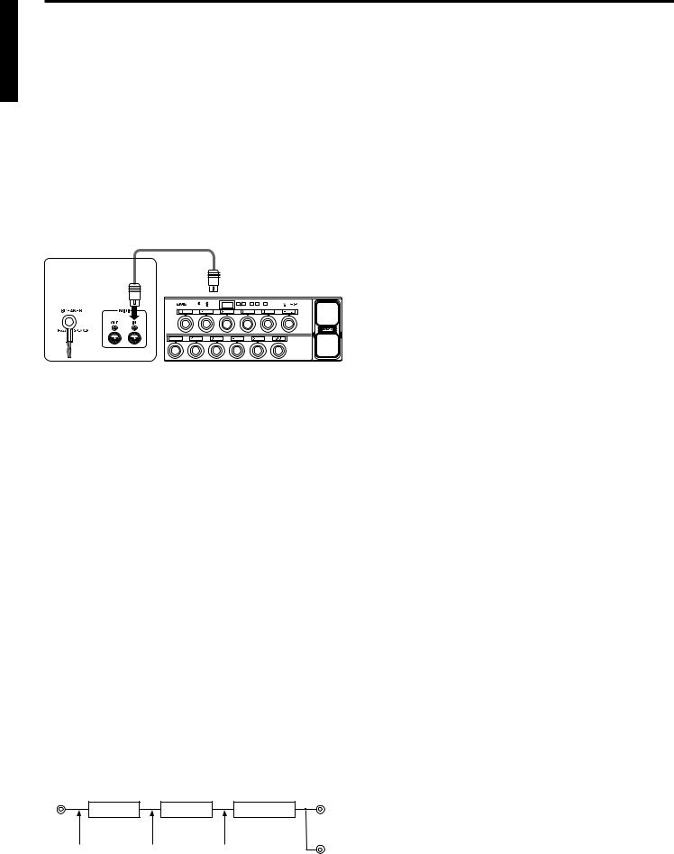
1.With a MIDI cable, connect the DG100-212’s MIDI IN jack to the MIDI OUT jack on an external MIDI device.
*Use only a standard MIDI cable that is less than 15 meters in length. Use of a longer cable may result in abnormal operation.
MIDI Cable
DG100-212
Rear Panel
|
MIDI OUT |
MIDI IN |
88.8.. |
External MIDI Device
2.Set the DG100-212’s MIDI receive channel and the MIDI transmit channel on the external device to the same MIDI channel number (the factory preset channel number is 1).
→For setting instructions see page 11 “Set the MIDI Receive Channel”.
3.Create a program change table*1.(The factory preset is, program change number = memory number).
→For setting instructions see page 11 “Creating a Program Change Table”.
*1 For example, “the received program change number 1, recalls the DG100212’s memory number 5”. To achieve this, the received program change number must be assigned to the corresponding memory number.
4.When program memory data is transmitted from an external MIDI device, data in the corresponding memory assigned to the program change table will be recalled.
*For instructions on how to transmit program change data, check the owner’s manual of the external MIDI device you are using.
■ Using MIDI to Control Volume
You can control the DG100-212’s overall volume from an external MIDI device using a number 7 control change message (main volume) sent from the MIDI OUT jack of an external MIDI device to the DG100-212’s MIDI IN jack. By connecting a Yamaha MIDI Foot Controller MFC10, etc., or a MIDI device equipped with a foot pedal, you can use the foot pedal to control the volume during performance. Using the following three positions, you can select the control position as to where the volume is changed.
•“bP” : Before Pre Amp. Controls the volume before the preamp.
•“AP” : After Pre Amp. Controls the volume after the preamp.
•“Ar” : After REVERB: Controls the volume after the reverb.
INPUT |
|
SPEAKER |
Pre Amp |
Reverb |
Power Amp |
1.Using procedures 1. and 2. in the previous “MIDI Memory Recall” section, connect the external MIDI device and set the MIDI receive channel.
2.Next, select the volume control position.
→For instructions on the setting procedure, refer to page 11 “Set the Volume Pedal Position”.
3.In this condition, number 7 control change data transmitted from an external MIDI device will now control the DG100-212’s volume.
*The DG100-212 does not except MIDI control changes other than numbers 7, 91 and 94.
*For more information on transmitting control data, refer to your external MIDI device’s owner’s manual.
*Even if another memory number is selected, main volume data will not change.
*When the power is switched ON, main volume data is set to its maximum level.
*After the main volume data is changed, and the external MIDI device is disconnected, the volume level may be insufficient. In this case, transmit the volume change again or, turn the power OFF and then ON again.
■ Using MIDI toTurn ON/OFF the Reverb and
Tape Echo Effects
You can turn ON/OFF the DG100-212’s REVERB effect from an external MIDI device using a number 91 MIDI control change message sent from the MIDI OUT jack of an external MIDI device to the DG100-212’s MIDI IN jack. In the same manner, a number 94 MIDI control change sent to the DG100212 will turn ON/OFF the DG100-212’s Tape Echo effect.
1.Using procedures 1. and 2. in the previous “MIDI Memory Recall” section, connect the external MIDI device and set the MIDI receive channel.
2.In this condition, number 91 or 94 control change data transmitted from an external MIDI device will now turn ON/OFF the DG100-212’s Reverb and/or Tape Echo.
*Regarding the DG100-212’s control change settings. A received control change equal to or greater than 64 will result in an “ON” setting. Less than or equal to 63 will result in an “OFF” setting. However, settings on the transmission side device should be set to 127 for “ON” and 0 for “OFF”.
*For more information on transmitting control data, refer to your external MIDI device’s owner’s manual.
■ Speaker Simulator
The DG100-212’s speaker simulator provides the line signal with a realistic simulation of the natural sound of a speaker. The speaker simulator can be used on the line signal when the LINE OUT jack is connected to a mixer or recorder.
→For setting instructions, refer to the “Speaker Simulator ON/OFF” section in this manual.
bP |
AP |
Ar |
LINE OUT
10
 Loading...