


550
Table of contents
 Loading...
Chapter
1
General Information
This service manual contains information useful for troubleshooting, repairing,
adjusting, and maintaining a Tektronix Phaser
includes troubleshooting guides, adjustment procedures, a field replaceable
units (FRU) list and assembly/disassembly procedures for selected FRUs. To
ensure complete understanding of the product, we recommend participation in
Phaser 550 service training.
®
550 Color Printer. This manual
Figure 1-1 The Phaser 550 Color Printer
9013-01
Service Manual
1-1

General Information
1
The Phaser 550 Color Printer
The Phaser 550 Color Printer combines a color laser, continuous-tone print
engine with an image processor supporting Adobe’s PostScript Level 2 page
description language. The image processor features a bi-directional parallel
interface for host communication. Optional network adapter cards to the image
processor allow the printer to communicate on networks using LocalTalk, serial,
Ethernet or Token Ring protocols. The Ethernet network card supports
EtherTalk, Novell and TCP/IP. With the Token Ring network card, the printer
supports Token Ring protocols. The network cards are sometimes referred to as
“smart cards” because each houses its own processor for executing specific
on-board protocols; only data is transferred from the installed smart card to the
printer’s image processor board. The PCL printer language is optionally
supported and is activated with a downloadable authorization code.
The Phaser 550 comes standard with 8 Mbytes of RAM which can be
supplemented with one or two additional 16- or 32-Mbyte RAM SIMMs;
maximum capacity is 72 Mbytes. The printer contains 17 standard, built-in
fonts. An additional 22 fonts can be added via an optional snap-in SIMM
(which also enables other extended features). The standard Phaser 550 prints at
a resolution of 600 x 600 dots-per-inch.
The addition of the extended feature (font) SIMM allows the printer to print at
higher resolutions of 600 x 600 (Standard mode), 1200 x 600 (Enhanced mode)
and 1200 x 1200 (Premium mode) dots per inch. The extended feature Phaser
550 also supports image pipelining for greater throughput, a print collation
mode, and a “check print before proceeding with job” mode.
The Phaser 550 support a 5 page-per-minute, composite-black printing called
Fast Color. It also feature Presentation mode printing in which a paper print is
printed with the color settings of a transparency print. Presentation mode
produces the smoothest and brightest large-area fills. This mode can only be
selected from the front panel. The printer print in monochrome at 14 prints per
minute.
The printer also feature a SCSI-compatible interface to connect to an external
hard disk drive for additional font storage. An orderable option, the Phaser
CopyStation can also be connected to the printer’s SCSI port to give the printer
the ability to optically copy color images. The printer requires a minimum of
24 Mbytes of RAM to support the CopyStation.
The printers support printing on A- and A4-sized paper and transparency film
from an A or A4-size tray. An optional two-tray second feeder (called the Lower
Tray Assembly) is available. The printer supports legal-size paper when fed
manually or from a Legal-size paper tray. The printer requires at least 12 Mbytes
of installed RAM to support Legal-size printing. The printer also supports
manual feeding.
1-2
Phaser 550 Color Printer

After being idle for one hour the printer switches into its Energy Star mode
where it consumes less than 45 watts of power. It “awakens” upon receiving
data at any of its ports. The printer also features a closed-loop image density
sensor system that allows it to auto-calibrate its color imaging so printing output
remains consistent over the life of the print engine and its consumable supplies.
Print speeds depend on the chosen resolution and selected media. For
resolutions of 600 x 600 (standard) and 1200 x 600 (enhanced) dpi, in color, the
printer prints at 3.5 pages per minute (ppm) on paper. Monochrome printing is
at 14 ppm on paper. Transparency film printing is always 1.5 ppm. For
1200 x 1200 (premium) dpi color printing, the printer color prints at 1.75 ppm.
Monochrome printing is at 7 ppm. Transparency film printing is 1.5 ppm. The
printer prints 600 x 600 dpi, composite black (CMY) draft prints at a rate of
5 pages per minute.
RAM and printer capabilities
The printer features 8 Mbytes of base RAM and two SIMM connectors which
accept both 16- or 32-Mbytes RAM SIMMs. With more memory the printer gains
the capabilities of printing at higher resolutions, printing without having to use
image compression (which trades off less installed RAM for longer image
processing time) and dual frame buffers for printing one image while processing
a second image (which gives greater printing throughput). With additional
RAM memory the printer’s capabilities increase as detailed in the following
table:
General Information
1
Table 1-1 Installed RAM and printer capabilities
Print mode 8 Mbytes 34 Mbytes 40 MBytes 56 Mbyte 72 Mbytes
600 x 600 dpi
3.5 ppm
1200 x 600 dpi
3.5 ppm,
extended
feature option
600 x 1200 dpi
1.75 ppm,
extended
feature option
1200 x 1200 dpi
1.75 ppm,
extended
feature option
1 frame buffer
with image
compression
NA
NA
NA
1 frame buffer
with no image
compression
2 frame buffers
with image
compression
2 frame buffers
with image
compression
1 frame buffer
with image
compression
2 frame buffers
with no image
compression
1 frame buffer
with no image
compression
1 frame buffer
with no image
compression
2 frame buffers
with image
compression
2 frame buffers
with no image
compression
1 frame buffer
with no image
compression
1 frame buffer
with no image
compression
2 frame buffers
with image
compression
2 frame buffers
with no image
compression
2 frame buffers
with no image
compression
2 frame buffers
with no image
compression
1 frame buffer
with no image
compression
Installing a single 4-Mbyte RAM SIMM in the image processor’s SIMM 1
connector (total of 12 Mbytes RAM installed) gives the printer the ability to print
full color on legal-size paper.
Service Manual
1-3
General Information
1
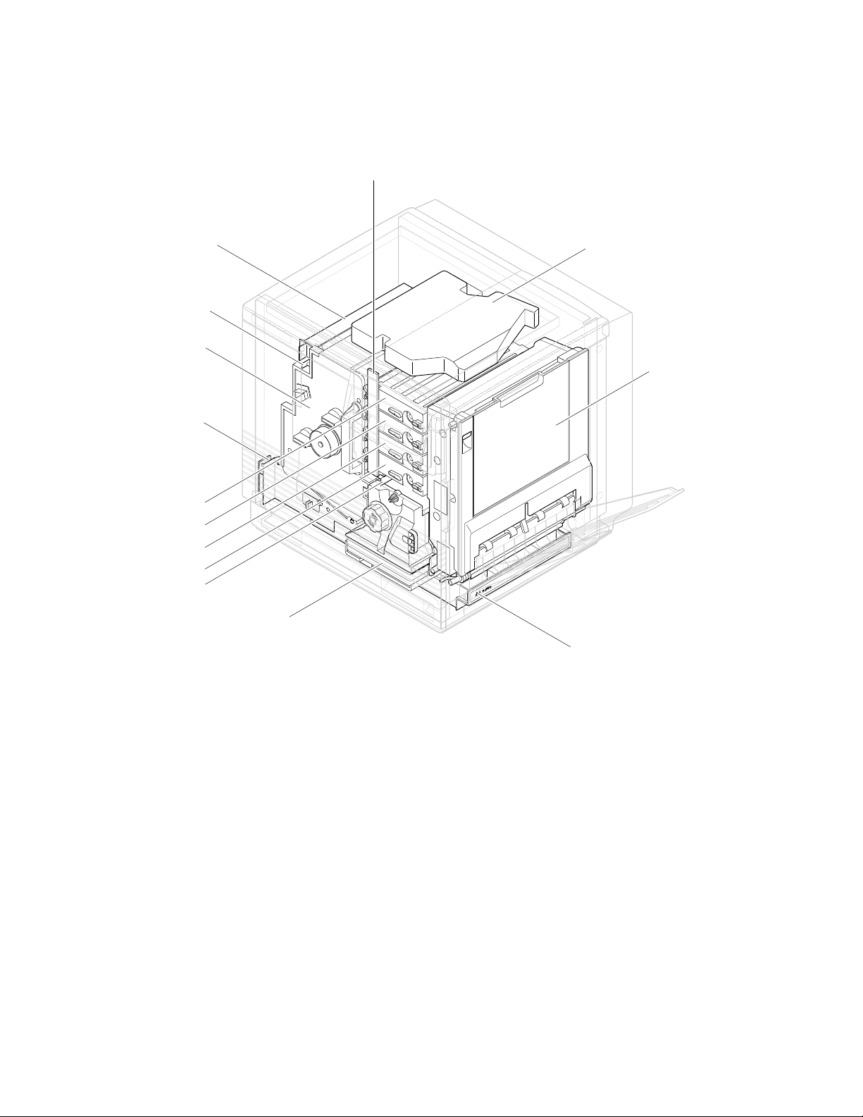
Print engine assemblies
Toner level
sensor board
Pre-exposure lamp
Imaging unit
Paper feeder
Black toner cartridge
Yelllow toner cartridge
Magentatoner cartridge
Cyan toner cartridge
Pre-transfer lamp
Ozone filter
Fuser
Laser scanner
Toner cartridge
selector/paper
exit unit
(right door)
ER
P
A
P
A4
Paper tray
9322-85
Figure 1-2 Print engine major components
The imaging unit may contain a removable pre-transfer corona unit. The
pre-transfer corona unit makes the imaging unit backwards compatible with the
Phaser 540 Color Laser Printer. Unlike the Phaser 540, the Phaser 550 does not
use a pre-transfer corona.
1-4
Phaser 550 Color Printer
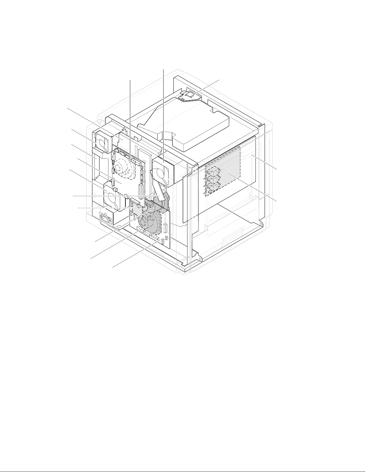
Toner cartridge
drive unit
Power
supply fan
Power
supply unit
Engine
control board
Fuser fan
Charger
sensor board
Cleaning board
Toner
cartridge
motor
Ozone fan
Laser motor drive board
General Information
Image processor
board
High voltage board
1
Main motor
Paper feed motor
Engine driver board
Figure 1-3 Print engine components (continued)
9322-86
Service Manual
1-5
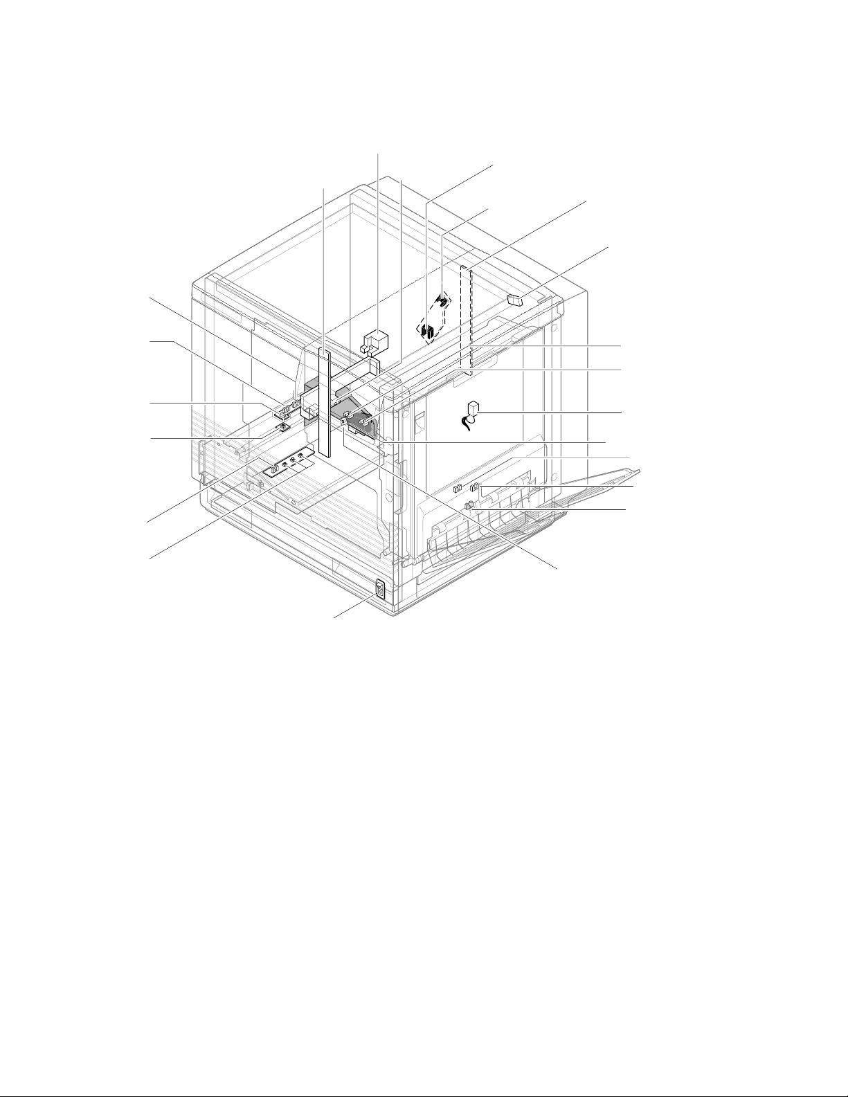
General Information
1
Manual feed
sensor
Accumulator belt
Toner level
sensors
(transmitters)
home position sensor
Image density
sensor
Scorotron
charger
sensor
Pre-transfer
charger
sensor
Toner level sensors
(receivers) are mounted
inside the toner cartridge
driver unit
Front right door
opened switch
Aligning
sensor
Transparency
sensor
(transmitter)
Transparency
sensor
(receiver)
Paper low
sensor*
Paper tray
type sensors
Power switch
*Unused by image processor
Figure 1-4 Print engine sensor, switch and solenoid locations
The photoconductive belt position sensor is not illustrated. This optical sensor
marks the home position of the photoconductive belt. It is mounted inside the
customer-replaceable imaging unit.
Transfer waste
bin sensor
Transfer roller
position sensor
Fuser-installed
switch
Left door opened
switch
Fuser-exit
sensor
Output tray full
sensor
Paper-exit
sensor
Paper-empty
sensor
9322-01
1-6
The logic state of the paper low sensor is not monitored nor used by the image
processor.
Phaser 550 Color Printer

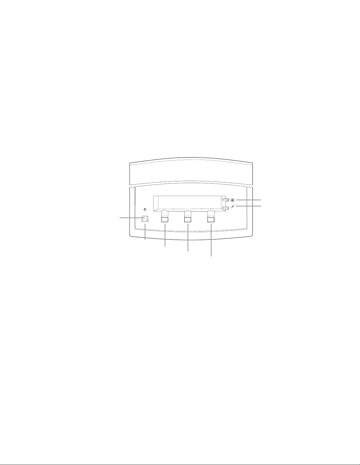
Front panel
General Information
These front panel features are found on the printer:
■
A two-line, 24-character LCD and two LEDs
Four push buttons
■
LCD
The LCD serves two purposes: displaying current controller and print
engine status information and displaying an interactive menu. Status
information includes controller status such as
Printing . Print engine status includes messages such as Out of paper ,
Paper Jam , and Out of toner . The interactive menu can only be entered
while the print engine and controller are idle. The interactive menu allows the
user to review and change certain NVRAM, I/O ports and peripheral
parameters. Using the front panel to review and change parameters is discussed
in Chapter 9, “Checks and Adjustments.”
Buttons
while in the interactive menu. The functions of Buttons 2, 3 and 4 are defined by
the particular menu or function being displayed on the LCD display. The
bottom row of the LCD labels the current function of each button.
Button 1, the left-most button labeled the Exit key, cancels an operation
Ready , Receiving data and
1
In addition, pressing the buttons as you turn on the printer enables certain
diagnostic modes:
Pressing and holding Button 1, as you turn on the printer, skips
■
power-up diagnostics (except for a brief kernel test) and proceeds to
PostScript startup.
■
Pressing and holding Button 2, as you turn on the printer, executes
extended diagnostics.
■
Pressing and holding Button 3, as you turn on the printer, executes
interactive service tests. These are described in “Printer
self-diagnostics” on page 9-6.
The Chapter 9 topic, “Resetting NVRAM” on page 9-31 explains how to use the
front panel buttons to reset the printer’s NVRAM to its factory default values.
Service Manual
1-7
General Information
On
1
LEDs
The Power LED indicates the printer has +5 VDC available for its logic
control boards.
The
Error LED has three indications:
■
Off indicates that no errors have been detected.
■
indicates a warning to the user. An explanatory message, such as
Low Paper , is displayed on the LCD.
Blinking indicates an error has been detected. An error message, such
■
Paper Jam at Output , is displayed on the LCD. Error codes
as,
are listed and explained in the Section 6 topic, “Error messages” on
page 6-19.
Power
Error
Exit
Exit
Button 1
Button 2
Button 3
Button 4
9013-06
1-8
Figure 1-5 The front panel and its functions
Phaser 550 Color Printer

Rear panel
General Information
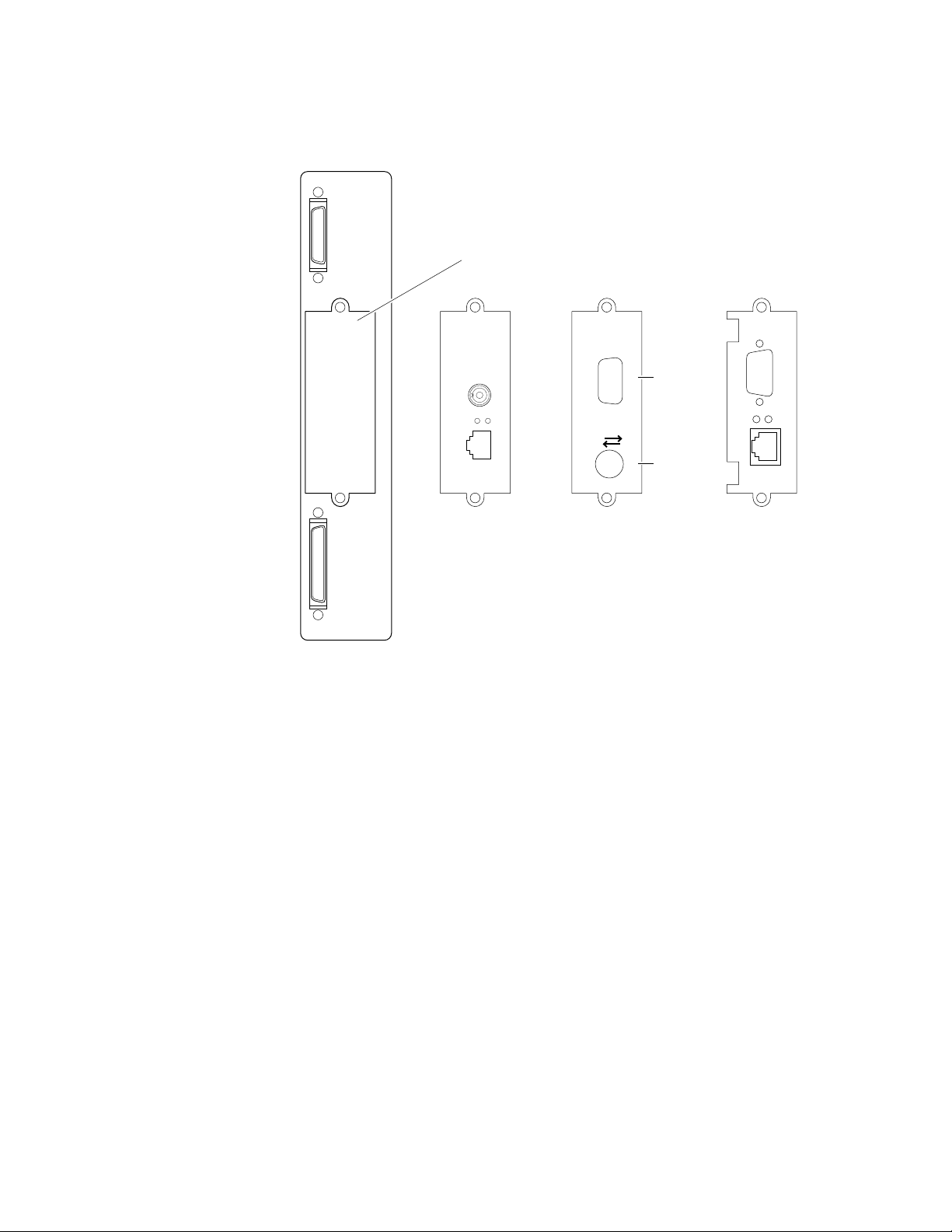
Connectors
The rear panel of the Phaser 550 printer features the host interface connectors to
the printer. It includes the following connectors:
Standard parallel (high-density connector).
■
■
SCSI high-density connector (font hard disk drive or
Phaser CopyStation only).
With the addition of a network card, the printer can feature either of these
groups of connectors:.
■
ThinNet (10base2) and Twisted Pair (10baseT) Ethernet connectors.
This is Option P1 and P2.
■
RS-232 serial and LocalTalk connectors. This is Option P2
1
Unshielded Twisted Pair (10baseT) and shielded Twisted Pair (DB-9)
■
Token Ring connectors. This is Option P4.
Service Manual
1-9
General Information
1
The figure below illustrates the rear panel.
Parallel
SCSI
Smart card slot
for network card
Phaser™ Share
Ethernet Card
10Base2
Link
RX
TX
10Base-T
Option
P1
P2
Figure 1-6 The Phaser 550 rear panel
LocalTalk/Serial Card
Phaser™ Share
Serial LocalTalk®
Option
P3
RS-232
serial
LocalTalk
Token Ring Card
PhaserShare™
Option
P4
9013-05a
Network card LEDs
The Ethernet network card has two LED indicators:
■
■
Note
1-10
Phaser 550 Color Printer
TX indicator (yellow); blinks while data is transmitted to the host. The
LED is off while no data is being sent.
Twisted Pair (10baseT). RX indicator (green); blinks while the
network card is receiving data. The LED is
being received. If the LED is
off steady , then a problem (probably
on steady while no data is
hardware) has occurred at the network hub.
ThinNet (10base2). RX indicator (green); blinks while the network
card is receiving data. The LED is
received. If the LED is
on steady , then a problem (probably hardware)
off stead y while no data is being
has occurred at the network hub.
Do not use both Ethernet connectors at the same time. If both are
used the 10base2 line is ignored.

on
on
Test print button
General Information
The Token Ring network card has two LED indicators:
■
Connection (yellow); off when the printer is not inserted into the Token
blinks while the printer is attempting to insert itself into the
Ring,
Token Ring,
Ring Speed (green); off when the card is set for 4 megabits per second
■
(MBPS),
When both LEDs blink, a network card failure has occurred.
■
In the center of the rear cabinet panel is the test print button. Pressing this
button while the printer is idle causes the print engine to print a built-in test
print. The print consists of a field of thin horizontal lines. The print is made
independently of the image processor board. Hold in the test button for at least
4 seconds before releasing, or until you hear the print process begin.
when the printer is properly inserted in the ring.
when the card is set for 16 MBPS.
1
Service Manual
1-11

General Information
On
1
Health LED
A health LED indicates the status of the image processor board. The health LED
is mounted on the image processor board and is viewable through the grill
behind the manual feed tray. (The grill is the removable RAM SIMM options
cover.) Once the PostScript code is loaded into memory and the image processor
is initialized and running, the image processor blinks the LED at a one-second
rate.
Blinking (at a steady rate): The printer is operating normally. The LED
■
blinks irregularly during power-up self-diagnostics.
If a soft error occurs, the image processor board operates, but in a
reduced capacity. Soft failures include failure of expansion memory
SIMMs or any of the interface ports. When a soft error occurs, the
printer automatically prints a startup page listing the error.
■
or Off : A hard error condition has occurred that would keep the
image processor board from operating.
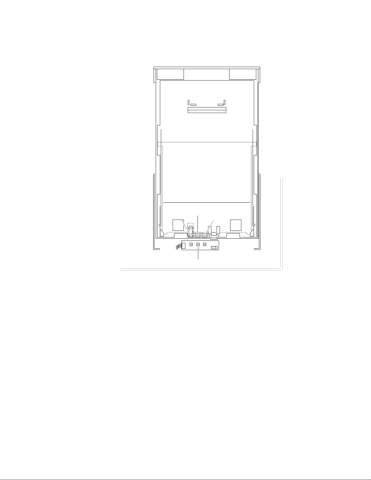
Media tray type sensing
The combinations of the three tray sensors “tell” the print engine what type of
paper tray is installed. The tray sensors are located on the left-side interior of
the paper tray slot. Sensor actuators are attached to the bottom end of the tray to
close the appropriate sensor. There are four tray types:
■
Letter (A-size) paper
Letter (A-size) transparency film
■
■ Metric Letter (A4-size) paper
■ Metric Letter (A4-size) transparency film
■ Legal-size paper
Table 1-2 Tray switch sensor combinations
Left switch Middle switch Right switch Tray type
Closed Open Open Letter (A-size) paper
1-12
Closed Closed Open Letter (A-size) transparency film
Open Open Closed Metric Letter (A4-size) paper
Closed Open Closed Metric Letter (A4-size) transparency film
Open Closed Open Legal size paper
Phaser 550 Color Printer
General Information
1
Sensor actuators
Middle
Left
Right
Tray sensors
Figure 1-7 Tray switch sensors and actuators
9013-40
Service Manual
1-13

1
General Information
Specifications
Table 1-3 Physical dimensions
Dimensions Specification
Height:
Width: 48.3 cm (19 in.) With output tray: 69.6 cm (27.4 in.)
Depth: 48.3 cm (19.5 in.)
45.7 cm (18 in.) With Lower Tray Assembly: 68.6 cm (27 in.)
Weight: Approximately 53.3 kgs (117 lbs.) with Lower Tray Assembly
and consumables installed.
Approximately 39.1 kgs (86.2 lbs.) without Lower Tray
Assembly.
Table 1-4 Printer clearances
Clearances Specification
Top: 7.6 cm (3 in.)
Left: 7.6 cm (3 in.)
Right: 10.2 cm (4 in.) for handling the output tray
Front: Unlimited for removal of consumable
Rear: 15.3 cm (6 in.) for connecting computer cable and pow er cord
Bottom: No obstruction under printer that could block its cooling vents.
Mounting surface
flatness:
Within 2 degrees of horizontal with all four feet in contact with
the table surface.
1-14
Phaser 550 Color Printer

General Information
Table 1-5 Functional specifications
Characteristic Specification
Printing process Electro-photographic, four color (CMYK) transfer printing
1
Color medium Four toner cartridges each contain one of four colors: cyan,
Addressability Standard, Fast Color and Presentation
Printing speed Time from paper-load to paper-eject:
Minimum printing
margins
Usable paper A-size (letter) and A4-size (Metric letter) of a good quality
magenta, yellow or black. The toner is a nonmagnetic,
monocomponent contact medium.
mode: 600 x 600 dots-per-inch text and graphics
Enhanced mode: 1200 x 600 dots-per-inch text and graphics
Premium mode: 1200 x 1200 dpi text and graphics
Four-color 3.5 pages per minute at 600 dpi
paper: 1.75 pages per minute at 1200 dpi
Monochrome: 14 pages per minute at 600 dpi
7 pages per minute at 1200 dpi
Four-color transparency: 1.5 pages per minute
Fast color, three-color
(CMY): 5 pages per minute at 600 dpi
Print times do not include image processing time, which can
vary depending on image complexity.
All sides, 5 mm (0.2 ins.).
premium laser printer or copier paper.
Tray feed paper weight: 75 to 105 g/m
Manual feed paper weight: 60 to 120 g/m
Double-sided printing is not supported.
Envelope printing is not supported.
2
(20 to 28 lb.)
2
(16 to 32 lb)
Paper tray capacity 250 sheets using 20-lb. paper. 100 sheets of transparency
film. The optional Lower Tray Assembly also uses trays with
the same capacity.
Service Manual
1-15

1
General Information
Table 1-6 Electrical specifications
Characteristic Specification
Primary line voltages 87 to 128 VAC (115 VAC or 100 VAC nominal); 174 to 260
VAC (220 VAC nominal)
Primary voltage
47 to 63 Hz
frequency range
Power consumption 60 watts (fuser off), 850 watts (fuser on) during Ready state,
950 watts during Warm-up, 45 watts during Energy Star state
Primary voltage fusing 110 VAC configuration – 10 amp
220 VAC configuration – 6.3 amp
Secondary DC voltages Image processor:
+ 5 VDC ± 0.25 (1A minimum, 6 A maximum)
± 12 VDC ± 0.6 (100 mA max)
Print engine:
+ 5V ± 0.25 (2.2 A max)
+ 12V ± 0.25 (0.4 A max)
- 12V ± 0.25 (0.1 A max)
+ 24V ± 0.25 (3.0 A max)
RF emissions Both 110 and 220 VAC-configured instruments pass these
standards: FCC Part 15 Class B
VDE Class B
EN55022 (CISPR 22) Class B
VCCI (CISPR 22) Class B
Table 1-7 Environmental specifications
Characteristic Specification
Temperature
Operating
Non-operating
Storage
Humidity
Operating
Non-operating
Altitude
Operating
Non-operating
Vibration/shock
Operating
Non-Operating
(vibration)
Non-operating (shock)
Acoustic Noise
(operating)
10o to 32.5o C (50oto 91oF)
o
0
to 40o C (32o to 104o F)
o
-20
to 60o C (-4
o
to 140o F)
Media should be acclimated 24 hours before using in the
printer.
10 to 80% relative humidity, non-condensing
10 to 90% relative humidity, non-condensing
Media should be acclimated 24 hours before using in the
printer.
0 to 2500 m (8,000 ft.) at 25
0 to 15000 m (50,000 ft.)
(Fuser maximum 4000 m (13,300 ft.)
May drop any side or corner 50 mm (2 in.) without impairment
of subsequent operation.
On five mutually perpendicular axes: 0.5 g, 25-minute sweep,
5 to 200 to 5 Hz, 100 to 200 sec./sweep cycle. No resonant
frequencies below 50 Hz.
30 g, trapezoidal flared pulse, 20 msec each axis.
Aver age sound le vel (LEQ) is less than 53 dbA. Peak noise in
standby mode is 47 dbA.
o
C
1-16
Phaser 550 Color Printer

Regulatory specifications
The printer is a recognized component in conformance with the following
regulatory standards:
■ The packaged product meets ASTM D4169-86 and ASTM D4728-87
Transportation Standards.
■ Listed UL 1950 Information Processing and Business Equipment.
■ Certified CSA C22.2 No. 950 Safety of Information Technology
Equipment, Including electrical Business Equipment.
■ GS licensed IEC 950 (1991) Second Edition; EN60950 Information
Processing and Business Equipment.
■ VDE 0871/6.78 (Class B) Regulation for the Radio Frequency Interface
Suppression of High Frequency Apparatus and Installations.
■ VDE 0875, Regulation for RFI Suppression of Electrical Equipment
and Installations
General Information
1
■ EN55022 (CISPR 22) Class B
VCCI (CISPR 22) Class B
■ FCC Class B (for 115 VAC equipment) pursuant to Sub-part J
of Part 15.
Service Manual
1-17


Appendix
D
Test Pattern Generator
The Test Pattern Generator contains PostScript scripts to start test patterns for a
number of Tektronix color printers. It allows you to test a printer as if it were
receiving a file from a host computer. The test patterns are generated by the
printer's image processor and then printed by the print engine.
Note
The Test Pattern Generator should contain firmware version 1.2 or
higher.
Service Manual
D-1

1.
2.
3.
4.
D
Test Pattern Generator
To use the Test Pattern Generator, do the following:
Select a test pattern to be printed using the Test Pattern Generator's
five DIP switches. The following tables lists the available test
patterns.
Plug the Test Pattern Generator onto the printer's parallel port. Use
the parallel cable adapter (013-0299-00) to convert between the Test
Pattern Generator’s Centronics-style connector and the printer’s
new-style, high-density parallel port connector. You do not have to
turn the printer off; you can plug in the Test Pattern Generator “hot.”
Press the Test Pattern Generator's START button. Its green LED
flashes as you press the button.
The printer will print the transmitted print file. The front panel
displays the message “Waiting for data,” with the READY light
flashing, for five minutes after a test print has been sent to the printer.
However, you do not have to wait five minutes before sending
another test print from the Test Pattern Generator; the printer will
accept another test print.
Besides print files, the test pattern generator also allows you to turn off and on
the printer's startup page.
Additionally, the Test Pattern Generator lets you set up a printer for printing
from a 4511A Network Interface. To do so, just select the appropriate DIP switch
setting.
Table D-1 Test Pattern Generator DIP Switch settings for Phaser 550
Pattern or function 1 2 3
Print quality test pattern On On On On On
Blank sheet Off On On On On
Engine Pattern 1
(100%)
Service print 1 Off Off On On On
Blank sheet On On Off On On
Engine pattern 2 (50%) Off On Off On On
Service print 2 On Off Off On On
Enable startup page Off Off Off On On
Disable startup page On On On Off On
On Off On On On
45
D-2
Phaser 550 Color Printer
Appendix
C
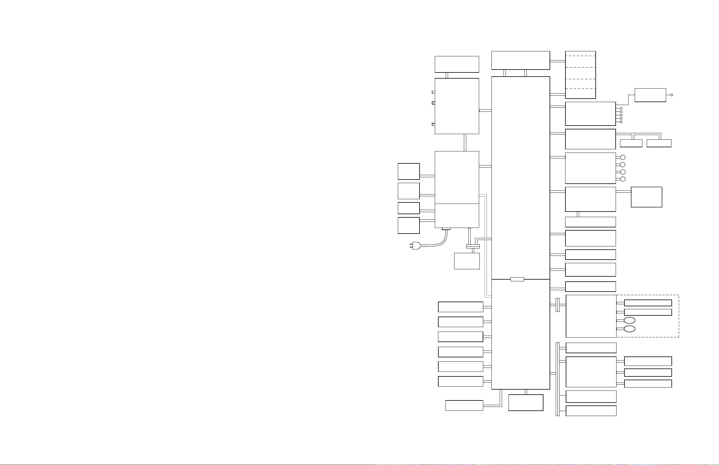
Wiring Diagram
Power
supply
fan
Door-
open
switch
Power
switch
Fuser-
installed
sensor
SCSI
Parallel
Network
card
Front panel
J219
J811
J211
J515
CN 853
CN 851
CN 802
CN 804
Image
processor
CN 854
Power
supply
J511
J921
CN 855
CN 852
CN 805
Laser driver board
CN 1
CN 11
CN 1
CN 5
CN 12
Engine
control
board
CN502
CN 16
CN 4
CN 9
CN 7
CN 6
CN 13
CN 540
Laser
scanner
CN 570
CN 701
High voltage
power supply
board
CN 627
Image density
sensor connector
CN 619
Toner cartridge
level sensor
(Receiver) and
roller clutch
board
CN 625
Charger unit
sensor board
CN 624
Imaging unit
CN 632
Accumulator belt
position sensor
Toner cartridge
sub bias board
FTR Orange
DEV Yellow
STR Black
CHG Red
GRID Blue
CN 628
BK sensor
CN 620
CN 621
CN622
CN623
CN 626 CN 630
B
Y
M
C
Pre-exposure
lamp
CMY sensor
Fuser
Left door closed
sensor
Fuser fan
Paper-feed motor
Developer cartridge
drive motor
Main motor
Cleaning board
Paper tray switches
CN 618
CN 307
CN 312
CN 304
CN 306
CN 305
CN 313
CN 302
CN 311
CN 2
CN 301
Engine
driver
board
CN 310
Optional
lower tray
assembly
CN 14
CN 17
CN 303
CN 309
CN 308
Ozone fan
Toner cartridge level
(transmitter) sensor
Pre-transfer lamp
CN 601
Paper
feeder
Exit tray full
CN 617
sensor
CN 611
Exit roller
sensor board
Toner cartridge
CN 615
movement sensor
CN 616
Cam motor
board
CN 603
CN 602
CN 606
CN 605
CN 614
CN 612
CN 613
Paper-pick sensor
Aligning sensor
Transfer roller solonoid
Aligning roller clutch
Fuser exit
CN 610
sensor
Switchback solenoid
Face switching solenoid
9322-65
Figure C-1 Wiring diagram
Service Manual
C-1


Contents
1 General Information
The Phaser 550 Color Printer 1-2
RAM and printer capabilities 1-3
Print engine assemblies 1-4
Front panel 1-7
Rear panel 1-9
Network card LEDs 1-10
Test print button 1-11
Health LED 1-12
Media tray type sensing 1-12
Specifications 1-14
Regulatory specifications 1-17
2 Installing the Printer and Drivers
Pre-install questions for customers 2-2
Unpacking 2-5
Printer inventory 2-5
Accessory box 2-5
Setting up the printer 2-7
Installing SIMM memory 2-7
Installing a font SIMM 2-7
Installing a network card 2-7
Cabling the printer 2-8
Connecting the printer to a Macintosh 2-8
LocalTalk connection to a Macintosh 2-8
Ethernet connection to a Macintosh 2-8
Connecting the printer to a PC 2-9
Direct connection to a PC 2-9
Networked connection using the Ethernet port 2-9
Networked connection using the Token ring port 2-9
Connecting the printer to a workstation 2-10
Direct connection to the workstation 2-10
Networked connection to a workstation 2-10
Networked connection using the Token Ring port 2-10
Connecting an optional SCSI hard disk drive to the printer 2-11
Connecting the optional CopyStation to the printer 2-12
Turning on the printer 2-13
The startup page 2-13
The configuration page 2-14
Service Manual
v

vi
Driver and communication set up 2-21
Loading the LaserWriter PPD file 2-21
Installing a printer driver for Microsoft Windows 95 2-22
Installing the Tektronix driver for Windows 3.1 2-24
If you have other Tektronix printer drivers already installed 2-24
Configuring the Tektronix Windows printer driver 2-25
Updating the standard Microsoft Windows PostScript driver 2-27
Installing the printer driver for OS/2 Version 2 2-28
Setting the printer’s IP address using the front panel 2-30
Configuring the printer's serial port for a PC 2-31
Using printcap to configure a workstation for the printer's serial port 2-33
Configuring a Novell NetWare server for the printer 2-34
Configuring TCP/IP on a UNIX host 2-35
3 Verifying the Printer and Host Connections
Macintosh verification 3-1
Selecting the printer via the Chooser 3-1
Printing the directory from a Macintosh 3-3
Verifying that an application communicates to the printer 3-4
Using the Error Handler utility 3-4
PC verification 3-5
DOS connection verification 3-5
Windows 95 driver verification 3-5
Windows 3.1 driver verification 3-6
OS/2 connection verification 3-6
Novell NetWare verification 3-7
Send a print file to the printer 3-7
Using the Error Handler utility 3-8
Workstation verification 3-9
Verifying connection and printing using TCP/IP protocols 3-9
Using the Error Handler utility 3-10
Phaser 550 Color Printer

4 Key Operator Training
Overview 4-1
Printer controls and indicators 4-2
Loading media 4-3
Customer-replaceable consumables 4-4
Imaging unit 4-4
Toner cartridges 4-4
Transfer roller 4-4
Fuser 4-4
Clearing paper jams 4-5
Cleaning 4-5
Warranty information 4-6
Service support 4-6
Supplies ordering 4-7
If you need help 4-7
Using the automated fax systems 4-7
Tektronix Color Printer Information Server 4-10
Customer Support Hotline 4-10
Service support 4-11
Electronic bulletin board service 4-11
5 Theory of Operation
Overview 5-1
Functional block diagram 5-2
Laser imaging 5-4
Overview 5-4
Pre-exposure 5-6
Electrostatic charging 5-7
Laser exposure 5-8
The laser scanner 5-9
Toner pickup (development) 5-10
Toner transfer to the accumulator belt 5-11
Paper picking 5-12
Toner transfer to paper 5-13
Fusing and exiting 5-14
Print modes 5-15
Printer color correction 5-16
Power supply 5-17
Image processor 5-18
Image rendering technology 5-18
Service Manual
vii

6 Troubleshooting
System power-up sequence 6-1
Print engine troubleshooting 6-2
Testing the print engine 6-2
Verifying printer operation by using its self-test print 6-3
Verifying power supply operation 6-3
Measuring power supply voltages 6-3
Inspecting the power supply fuses 6-5
Safety interlocks 6-5
Testing for a shorted motor 6-6
Testing motor resistances 6-7
Media jams and the paper path 6-8
Media-based problems 6-8
Media problems 6-8
Multiple-sheet pick 6-8
The printer is not distinguishing between paper and transparency film 6-9
The media skews passing through the paper path 6-9
Paper tray indicates empty when it is not 6-10
No paper feeder installed 6-10
No imaging unit installed 6-10
Jams 6-11
Paper mis-picks at the paper tray 6-11
Paper jams midway in the paper feeder 6-11
Paper jams at the second bias transfer roller 6-12
Fuser jams 6-13
Eject jams 6-13
Manual feed jams 6-14
Other problems 6-15
The printer continuously displays “Initializing” 6-15
Transfer roller waste tray indicates not full when it is 6-15
No toner cartridge installed when it is 6-16
No fuser installed when it is 6-16
Front door open when it is closed 6-16
Left-side door open when it is not 6-16
High temperature error 6-17
Low temperature error 6-17
High voltage error 6-17
Thermistor open error 6-18
Power supply fan does not run 6-18
Front Panel Cycling between READY and WARMING UP 6-18
viii
Phaser 550 Color Printer

ix
Error messages 6-19
Print engine error codes 6-19
Printing and print quality problems 6-24
Blank print 6-24
All-black print 6-24
Missing primary color 6-25
Light print 6-25
Repeated spots or lines on print in-line with each other 6-26
Dark vertical line in print 6-26
Missing primary color on one side of print 6-26
White horizontal line or band in all the colors of a print 6-27
White vertical lines in the print 6-27
Dirty background 6-27
Mis-transfer, missing portions of toner 6-27
Partial black dots 6-27
Dark, irregular steaks in all colors 6-28
Ghosting 6-28
Unfused or partially fused printing 6-28
Image is skewed on the paper 6-28
Stains on the back of the print 6-29
No printing on edge of print 6-29
Image is not centered on the print when it should be 6-29
The print is wrinkled 6-30
Macintosh printing problems 6-31
Image never prints 6-31
Image prints in black-and-white 6-31
Image is rotated 90 degrees 6-31
Printer isn’t in the Chooser 6-32
PC DOS printing problems 6-32
Image never prints 6-32
Windows printing problems 6-34
Image never prints 6-34
Blue color on the screen is printing too purple 6-34
Windows message “Problem writing device LPT1: Cancel or Retry” 6-34
Workstation printing problems 6-35
Image never prints 6-35
Service Manual

x
7 Cleaning and Maintenance
Service preventive maintenance procedure 7-1
Recommended tools 7-1
Cleaning 7-2
Lubrication 7-2
8 FRU Disassembly/Assembly
Required tools 8-1
The printer cabinet 8-2
Upper rear cover 8-2
Lower rear cover 8-2
Top cover 8-2
Left door (for paper feeder access) 8-2
Left side cover 8-2
Manual feed tray 8-2
Front door 8-4
Upper and lower front covers 8-4
Bottom front cover 8-4
Front panel board 8-4
Toner level sensor board 8-4
Right side covers (front, rear and lower) 8-5
Paper feeder 8-6
Paper tray sensor board 8-6
Cartridge selector/eject unit (right door) 8-8
Laser scanner 8-9
Laser motor drive board 8-10
Power supply 8-11
Fuser installed switch 8-11
Power supply fuse 8-13
Printer rear assemblies 8-14
Engine control board 8-14
Engine driver board 8-14
Charger sensor board 8-15
Main motor 8-16
Paper feed motor 8-16
Cleaning board 8-16
Toner cartridge drive unit 8-18
Home position sensor assembly and the left door opened switch 8-18
Phaser 550 Color Printer

xi
High-voltage board 8-20
Pre-exposure lamp 8-21
Pre-transfer lamp 8-21
Toner auto-density sensor 8-21
Image processor board 8-23
Installing RAM SIMMs 8-24
Installing an Extended Features SIMM 8-26
Installing a network card 8-28
Enabling TCP/IP with the authorization code 8-29
Replacing the code ROM SIMM 8-30
9 Checks and Adjustments
Required tools 9-1
Front panel menu 9-2
Printing test prints 9-4
Print service test prints 9-4
Printing the configuration page 9-4
Printing the demonstration pages 9-4
Printing the print engine’s test print 9-4
Image processor normal indicators 9-5
Image processor hard and soft error indicators 9-5
Printer self-diagnostics 9-6
Service mode status code meanings 9-11
Resetting NVRAM 9-31
Print engine calibration 9-32
Printer color correction 9-32
Starting printer semi-automatic color correction 9-32
Manually setting color corrections 9-32
Checking print registration 9-34
A Field Replaceable Units List
B Test Prints
C Wiring Diagram
D Test Pattern Generator
Index
Service Manual

Figures
Figure 1-1
Figure 1-2
Figure 1-3
Figure 1-4
Figure 1-5
Figure 1-6
Figure 1-7
Figure 2-1
Figure 2-2
Figure 2-3
Figure 5-1
Figure 5-2
Figure 5-3
Figure 5-4
Figure 5-5
Figure 5-6
Figure 5-7
Figure 5-8
Figure 5-9
Figure 5-10
Figure 5-11
Figure 5-12
Figure 5-13
Figure 5-14
The Phaser 550 Color Printer 1-1
Print engine major components 1-4
Print engine components (continued) 1-5
Print engine sensor, switch and solenoid locations 1-6
The front panel and its functions 1-8
The Phaser 550 rear panel 1-10
Tray switch sensors and actuators 1-13
The Phaser 550 and its packaging 2-6
Connecting a SCSI hard disk drive to the Phaser 550 2-11
Connecting a CopyStation to the Phaser 550 2-12
Block diagram of the printer 5-2
Laser printing process overview 5-5
Pre-exposing the photoconductive belt 5-6
Electrostatic charging of the photoconductive belt 5-7
Laser exposure of the photoconductive belt 5-8
The laser scanner 5-9
Toner pickup 5-10
Toner transfer to the accumulator belt 5-11
Paper picking 5-12
Transferring toner to the paper 5-13
Fusing the toner to the paper 5-14
Print modes and printing dots 5-15
The power supply 5-17
The image processor graphics pipeline 5-19
Figure 6-1
Figure 6-2
xii
Measuring the DC voltages (test points) 6-4
Door safety interlock switches 6-6
Phaser 550 Color Printer
Loading...