


AGB 664/WP
Whirlpool AGB 664/WP, AGS 654/WP, AGB 666/WP, AGB 673/WP, AGB 786/WP INSTRUCTION FOR USE
...
LAVASTOVIGLIE PROFESSIONALI
PROFESSIONAL DISHWASHERS
LAVE-VAISSELLE A USAGE COLLECTIF
PROFESSIONELLER GESCHIRRSPÜLER
LAVAVAJILLAS PROFESIONAL
MÁQUINA DE LAVAR LOUÇA PROFISSIONAL
MANUALE D’ USO ED INSTALLAZIONE
MANUAL FOR USE AND INSTALLATION
MANUEL D’ EMPLOI ET MISE EN PLACE
GEBRAUCHSANWEISUNG UND INSTALLATION
MANUAL DE INSTALACIÓN DE USO
MANUAL DE INSTALAÇO USO
MODELS – MODELES – MODELLE – MODELLI - MODELOS
AGB 669/WP AGB666/WP
AGB669/DP AGB666/DP
AGB672/WP AGB670/WP
AGB664/WP AGB670/DP
1 Avvertenze per la sicurezza e l’uso
2 Caratteristiche tecniche
3 Installazione e posizionamento
4 ISTRUZIONI PER L’INSTALLATORE - ASSISTENTE TECNICO
5 Prima messa in funzione
6 Settaggi
7 Anomalie visualizzate a display (tecnico)
8 ISTRUZIONI PER L’UTENTE
9 Scelta del programma
10 Manutenzione e pulizia
11 Problemi ed anomalie (utente)
12 Anomalie visualizzate a display (utente)
Vi ringraziamo per la scelta del prodotto.
Consigliamo di leggere attentamente tutte le istruzioni contenute nel manuale per conoscere le condizioni più
idonee per un corretto utilizzo della lavastoviglie.
ISTRUZIONI TECNICHE:
Sono destinate al personale qualificato che deve eseguire l’installazione, la messa in
servizio, il collaudo, ed eventuali interventi di assistenza.
ISTRUZIONI PER L’UTENTE:
Indicano i consigli d’uso, la descrizione dei comandi e le corrette operazioni di pulizia e
manutenzione della lavastoviglie.
2
1 Avvertenze per la sicurezza e l’uso
QUESTO MANUALE COSTITUISCE PARTE INTEGRANTE DELLA LAVASTOVIGLIE;
OCCORRE CONSERVARLO SEMPRE INTEGRO UNITAMENTE ALL’APPARECCHIO.
LA LAVASTOVIGLIE E’ DESTINATA ESCLUSIVAMENTE AD USO PROFESSIONALE E DEVE ESSERE
UTILIZZATA DA PERSONALE ABILITATO. E’ PREDISPOSTA PER IL LAVAGGIO DI STOVIGLIE (PIATTI,
TAZZE, CIOTOLE, TEGLIE, POSATE) E SIMILI NEI SETTORI GASTRONOMICI E NEL RAMO DELLA
RISTORAZIONE COLLETTIVA, ED E’ CONFORME ALLE NORME INTERNAZIONALI DI SICUREZZA
ELETTRICA E MECCANICA (CEI-EN-IEC 60335-2-58/61770) E DI COMPATIBILITA’ ELETTROMAGNETICA
(CEI-IEC-EN 55014-1/-2, 61000-3;4, 50366).
IL COSTRUTTORE DECLINA OGNI RESPONSABILITA’ PER DANNI A PERSONE O COSE CAUSATI
DALL’INOSSERVANZA DELLE ISTRUZIONI PRESENTI NEL MANUALE, DALL’USO NON CORRETTO,
DALLA MANOMISSIONE ANCHE DI UNA SINGOLA PARTE DELL’APPARECCHIO E DALL’UTILIZZO DI
RICAMBI NON ORIGINALI.
QUESTO APPARECCHIO E’ CONTRASSEGNATO IN CONFORMITA’ ALLA DIRETTIVA EUROPEA
2002/96/EC, WASTE ELECTRICAL AND ELECTRONIC EQUIPMENT (WEE).
ASSICURANDOSI CHE QUESTO PRODOTTO SIA SMALTITO IN MODO CORRETTO L’UTENTE
CONTRIBUISCE A PREVENIRE LE POTENZIALI CONSEGUENZE NEGATIVE PER L’AMBIENTE E LA
SALUTE.
IL SIMBOLO
QUESTO PRODOTTO NON DEVE ESSERE TRATTATO COME RIFIUTO DOMESTICO MA DEVE ESSERE
CONSEGNATO PRESSO L’IDONEO PUNTO DI RACCOLTA PER IL RICICLAGGIO DI APPARECCHIATURE
ELETTRICHE ED ELETTRONICHE.
DISMETTERE L’APPARECCHIO SEGUENDO LE NORMATIVE LOCALI PER LO SMALTIMENTO DEI
RIFIUTI.
PER ULTERIORI INFORMAZIONI SUL TRATTAMENTO, RECUPERO E RICICLAGGIO DI QUESTO
PRODOTTO, CONTATTARE IL COMPETENTE UFFICIO LOCALE, IL SERVIZIO DI RACCOLTA DEI RIFIUTI
DOMESTICI O IL NEGOZIO PRESSO IL QUALE IL PRODOTTO E’ STATO ACQUISTATO.
IL POSIZIONAMENTO, GLI ALLACCIAMENTI, LA MESSA IN FUNZIONE E L’ELIMINAZIONE DI
INCONVENIENTI, E LA SOSTITUZIONE DEL CAVO DI ALIMENTAZIONE DEVONO ESSERE
ESEGUITI DA PERSONALE QUALIFICATO.
E’ OBBLIGATORIO IL COLLEGAMENTO DI TERRA SECONDO LE MODALITA’ PREVISTE
DALLE NORME DI SICUREZZA DELL’IMPIANTO ELETTRICO.
SUL PRODOTTO O SULLA DOCUMENTAZIONE DI ACCOMPAGNAMENTO INDICA CHE
NON INTRODURRE SOLVENTI COME ALCOL O TREMENTINA CHE POTREBBERO
PROVOCARE UN’ESPLOSIONE. NON INTRODURRE STOVIGLIE SPORCHE DI CENERE,
CERA, VERNICI.
NON UTILIZZARE MAI LA LAVASTOVIGLIE O SUE PARTI COME SCALA, SUPPORTO O
SOSTEGNO PER PERSONE, COSE O ANIMALI.
APPOGGIARSI O SEDERSI SULLA PORTA APERTA DELLA LAVASTOVIGLIE POTREBBE
CAUSARNE IL RIBALTAMENTO, CON CONSEGUENTE PERICOLO PER LE PERSONE.
NON LASCIARE LA PORTA DELLA LAVASTOVIGLIE APERTA IN QUANTO VI SI POTREBBE
INCIAMPARE.
NON BERE L’ACQUA RESIDUA EVENTUALMENTE PRESENTE NELLE STOVIGLIE O NELLA
LAVASTOVIGLIE AL TERMINE DEL PROGRAMMA DI LAVAGGIO.
L’APPARECCHIO NON E’ ADATTO PER L’USO DA PARTE DI MINORI E PERSONE CON
RIDOTTE CAPACITA’ FISICHE, SENSORIALI O MENTALI, MANCANTI DI ESPERIENZA E
CONOSCENZA. L’UTILIZZO DELL’APPARECCHIO E’ CONSENTITO A QUESTE PERSONE
SOLO SOTTO LA SUPERVISIONE DI UNA PERSONA RESPONSABILE DELLA LORO
SICUREZZA.
3
2 Caratteristiche tecniche
AGB672
AGB669
AGB666
AGB670
Tensione di alimentazione V
400V/3+N
230V/1
400V/3+N
230V/1
Frequenza Hz 50 50 50
Potenza max. assorbita kW 6,75 7,1 10,75
Potenza resistenza boiler kW 6 6 10
Potenza resistenza vasca kW 3 3 3
Potenza pompa lavaggio kW 0,75 1,1 0,75
Pressione acqua alimentazione kPa 200-400 200-400 200-400
Temperatura acqua alimentazione °C 50 – 60 50 – 60 15 – 30
Durezza acqua alimentazione °dF 7 – 12 7 – 12 7 – 12
Consumo acqua per ciclo di risciacquo l 3,5 3,5 3,5
Capacità boiler l 9 9 12
Capacità vasca l 28 35 28
AGB664
400V/3+N
230V/1
Durata cicli standard con alimentazione acqua a 50°C s 60/120/180/C 60/120/180/C 60/120/180/C
Livello rumorosità dB(A) 67 67 67
Grado protezione IPX 4 4 4
Peso netto kg 115 123 118
Tipo di cavo di alimentazione ◄HAR► H05VV-F H05VV-F H05VV-F
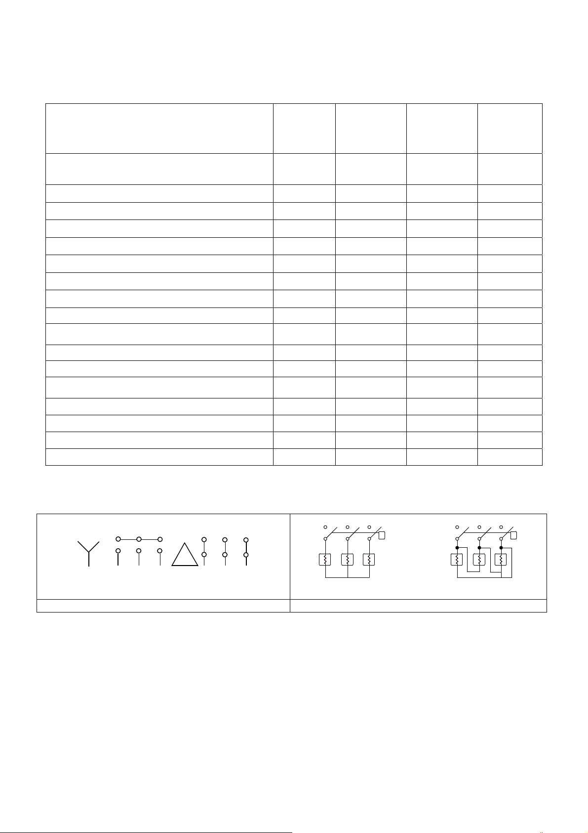
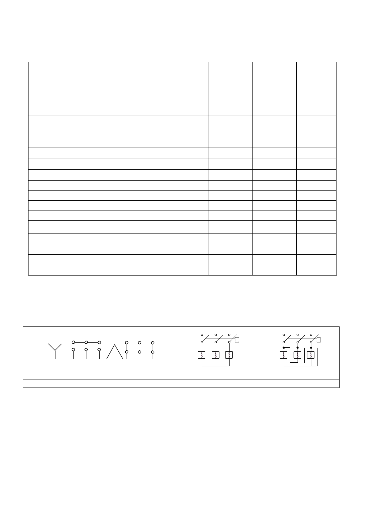
Schema elettrico – cambio tensione
400/3 Volt
RST RST
230/3 Volt
TRB
400/3 Volt
Pompa Lavaggio Resistenza Boiler
TRB
230/3 Volt
4

3 Installazione e posizionamento
INSTALLAZIONE e POSIZIONAMENTO
Portare la lavastoviglie sul luogo di installazione, rimuovere l’imballo, verificare l’integrità dell’apparecchio e dei
componenti, in caso di danni questi devono essere notificati per iscritto al trasportatore.
Gli elementi di imballaggio (sacchetti di plastica, polistirolo espanso, chiodi, ecc.) non devono essere lasciati
alla portata di bambini ed animali domestici, in quanto potenziali fonti di pericolo.
Tutti i materiali utilizzati per l’imballo sono compatibili con l’ambiente. Essi possono essere conservati senza
pericolo, o essere smaltiti presso un apposito centro di smaltimento rifiuti.
I componenti in materiale plastico soggetti ad eventuale smaltimento con riciclaggio sono contrassegnati nei
seguenti modi:
PE polietilene: pellicola esterna imballo, sacchetto istruzioni, sacchetti di protezione.
PP polipropilene: reggette.
PS polistirolo espanso: angolari di protezione, coperchio imballo.
I componenti in legno e cartone possono essere smaltiti rispettando le norme vigenti.
Alla dismissione del prodotto evitare di disperderlo nell’ambiente; lo smantellamento deve avvenire nel rispetto
delle norme vigenti. Tutte le parti metalliche sono in acciaio inossidabile e smontabili.
Le parti in plastica sono contrassegnate con il simbolo del relativo materiale.
POSIZIONAMENTO:
Attenzione:
devono rispondere alle normative vigenti.
Il costruttore declina ogni responsabilità per danni diretti o indiretti a persone o cose derivanti dal mancato
rispetto di dette normative.
Prima dell’installazione verificare che nelle adiacenze non vi siano o siano adeguatamente protetti, oggetti e
materiali che potrebbero essere danneggiati dal vapore acqueo o da schizzi di soluzione di lavaggio.
Posizionare la lavastoviglie nel punto desiderato e togliere la pellicola protettiva.
Livellare la lavastoviglie (aiutandosi con una livella) sui quattro piedini regolati in modo da garantirne la
stabilità; ogni altra soluzione deve essere approvata dal costruttore.
l’impianto interno ed i locali in cui vengono installate apparecchiature per comunità,
4 ISTRUZIONI PER L’INSTALLATORE
ASSISTENTE TECNICO
Allacciamento idraulico e scarico:
I tubi idraulici ed il cavo di alimentazione elettrica fuoriescono dalla zona posteriore. Allacciare il tubo di
alimentazione idrica ad una presa con bocca filettata ¾” gas.
Per il collegamento alla rete idrica utilizzare solamente tubi nuovi; tubi vecchi o usati non devono essere
utilizzati.
La pressione dinamica di alimentazione dovrà essere compresa tra 2 e 4 bar, se superiore è necessario
installare un riduttore di pressione.
E’ indispensabile installare un rubinetto generale sulla tubazione di arrivo acqua di alimentazione; il rubinetto
dovrà essere accessibile ad installazione terminata, non installare il rubinetto dietro la lavastoviglie.
La durata cicli dichiarata è riferita ad alimentazione con acqua calda 50°C.
In caso di alimentazione ad acqua fredda la durata potrebbe aumentare in relazione alla temperatura
dell’acqua in ingresso, essendo la lavastoviglie dotata di risciacquo a temperatura e pressione costanti.
Scarico:
Ogni lavastoviglie è già dotata di tubo per il collegamento allo scarico; questo sarà da prevedersi a pavimento,
con piletta a sifoide.
5
Attenzione: accertarsi che i tubi di alimentazione e scarico non siano piegati, strozzati o schiacciati
dopo l’installazione.
4.1 Allacciamento elettrico
Il collegamento elettrico della lavastoviglie ed eventuali apparecchi supplementari va affidato a
personale autorizzato e qualificato, nel rispetto delle norme vigenti; osservare inoltre le disposizioni
tecniche di allacciamento.
La potenza totale installata è riportata sulla targhetta dati tecnici dell’apparecchio.
Insieme alla lavastoviglie non devono essere protetti altri apparecchi.
L’esercente dovrà provvedere all’installazione, secondo le norme vigenti, di un interruttore generale
sulla linea di alimentazione elettrica e di un interruttore differenziale compatibile con le caratteristiche
della macchina.
Tali interruttori devono essere installati vicino alla lavastoviglie, essere facilmente accessibili dopo
l’installazione e garantire la disconnessione completa della rete elettrica nelle condizioni della
categoria di sovratensione III.
Attenzione!!!
La lavastoviglie è priva di tensione solamente quando l’interruttore generale è disinserito.
- Collegare l’apparecchio al sistema equipotenziale utenza. Il morsetto
nella zona posteriore inferiore della macchina.
- Il conduttore di protezione (PE) è di colore giallo-verde, il conduttore neutro (N) di colore blu e i
conduttori di fase (L1, L2, L3) di colore nero, grigio e marrone.
per il collegamento è posto
5 PRIMA MESSA IN FUNZIONE
PRIMA MESSA IN FUNZIONE
Il sistema elettrico di protezione deve essere sottoposto ad un test funzionale prima della messa in esercizio.
L’installazione deve essere eseguita e/o verificata dal rivenditore autorizzato che si occuperà della prima
messa in funzione e delle istruzioni relative al funzionamento della lavastoviglie.
PREPARAZIONE ALL’USO
Importante:
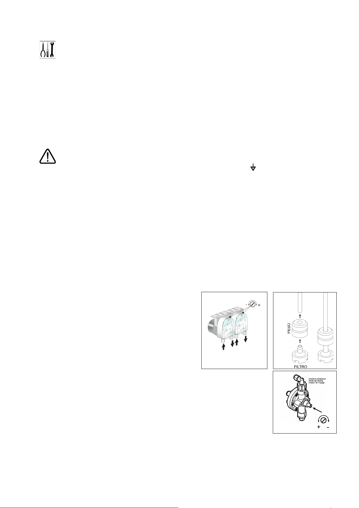
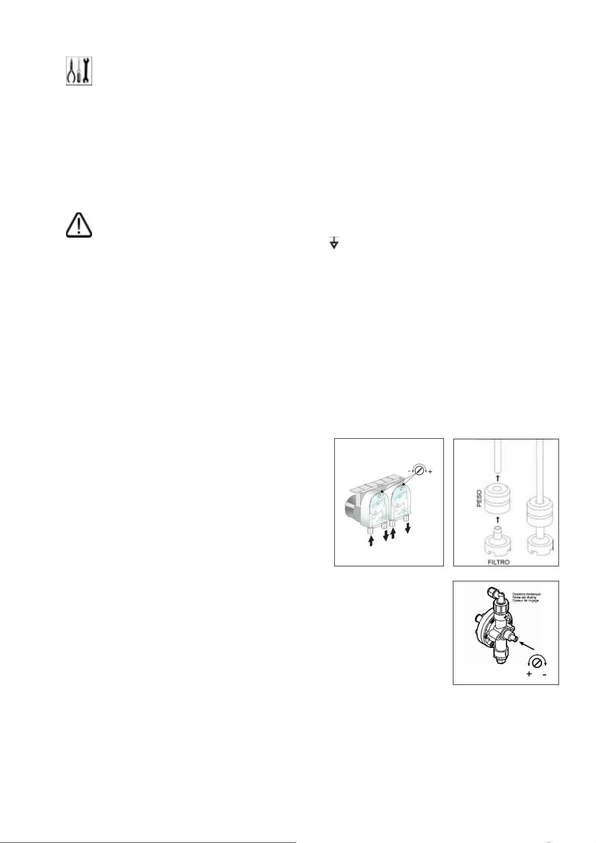
Il dosatore brillantante è sempre presente, il dosatore
detersivo solamente su alcuni modelli.
Se entrambi i dosatori sono presenti posizionare i
contenitori esterni di detergente e brillantante ed inserirvi i
rispettivi tubi di pescaggio posti sul retro della macchina.
Tubo rosso: detergente
tubo trasparente: brillantante
Prima di introdurre i tubi nei contenitori applicare alle
estremità il peso (necessario a mantenere il pescaggio sul
fondo del contenitore) ed il filtro come indicato in figura.
Per la regolazione agire sulle viti di regolazione indicate in figura, si raccomanda di
fare eseguire la regolazione dal personale delle società fornitrici di prodotti di
detergenti.
Se il dosatore detergente non è premontato, è possibile installarlo successivamente
ordinando il KIT relativo.
In alternativa è possibile collegare un dosatore esterno eseguendone il collegamento
elettrico con un cavo 2x0,5 mm tipo H05 RN-F, inserito attraverso il passaggio indicato
nello schema CARATTERISTICHE TECNICHE e collegato come da schema elettrico
in dotazione alla lavastoviglie. Il dosatore deve essere 230V/50 Hz con potenza
massima assorbita di 15 W.
Collegare al dosatore detergente esterno alla lavastoviglie attraverso il tubo rosso sopracitato.
6
6 SETTAGGI
SETTAGGI
Durante la prima messa in funzione provvedere all’impostazione o regolazione delle funzioni/parametri
di seguito indicati:
ALIMENTAZIONE : 200 – 250 VAC.
POTENZA ASSORBITA : 4 VA
TEMPERATURA DI FUNZIONAMENTO : 0 / 60 °C
UMIDITA’ DI FUNZIONAMENTO : max 90 % senza condensazione
NORMATIVE : la scheda e’ progettata e costruita in osservanza alle vigenti normative
europee in materia di sicurezza elettrica e di compatibilita’ elettromagnetica.
In particolare le seguenti:
EN 61000-6-3 : Emissione per ambienti residenziali e commerciali
EN 61000-6-2 : Immunita’ per ambienti industriali
EN 61000-4-11 : Immunita’ alle microinterruzioni di rete
EN 60335-1 : direttiva sicurezza bassa tensione
ZERO CROSSING : il rele’ che alimenta la resistenza elettrica della vasca e’ dotato della
funzione “ zero crossing “, che sincronizza la commutazione di questo rele’, sia in chiusura
che in apertura, con il passaggio per lo zero della tensione di rete, sia per frequenze di rete
di 50 Hz che per 60 Hz. In questo modo si riduce notevolmente l’usura dei contatti di
questo rele’.
SCHEMA DI COLLEGAMENTO
Morsetto Collegamento
1 – 2 ALIMENTAZIONE SCHEDA , 230 VAC
3 – 4 SONDA TEMPERATURA BOILER
5 – 6 SONDA TEMPERATURA VASCA
10 PRESSOSTATO BREAK-TANK
11 INGRESSO RISERVA
12 MICRO CAPOT
13 PRESSOSTATO VASCA , chiuso sopra livello
14 COMUNE INGRESSI
15 BOBINA TELERUTTORE RESISTENZE BOILER
16 RESISTENZA VASCA, max. 10 Amp.
17 18 -
18 B.TANK POMPA RISCIACQUO (TIPO MACCHINA 4)
19 POMPA DI LAVAGGIO ( max. 1 HP )
20 EV. RISCIACQUO + POMPA AUMENTO PRESSIONE
21 POMPA DI SCARICO ( max. 0.75 HP ) Optional
22 ALIMENTAZIONE USCITE, fase 230 VAC
PARAMETRI DI CONFIGURAZIONE MACCHINA ( Destinato al personale tecnico non all’utente
P0 TEMPO CICLO DI SCARICO, da 1 a 5 minuti, preimpostato a 2
P1 TEMPERATURA BOILER, da 60 a 95 °C, preimpostato a 86 °C
P2 TEMPERATURA VASCA, da 40 a 65 °C, preimpostato a 55 °C
P3 DURATA RISCIACQUO da 10 a 40 sec., preimpostato a 13 sec
Durante la fase di risciacquo viene attivata anche la pompa di scarico ( se installata ), che
viene tenuta attivata per 4 secondi dopo la fine della fase di risciacquo
)
7
P4 OPZIONE FERMO BOILER: 0 = non installato, 1 = installato, preimpostato a 0
P5 TIPO MACCHINA:
5 = con tre cicli di lavaggio senza Break Tank/Air Trap per Capot
6 = con tre cicli di lavaggio con Break Tank /Air Trap per Capot
P6 OPZIONE SCARICO CON TROPPOPIENO : 0 = non installato. 1 = installato, preimpostato a 1
Lo scarico viene attivato ogni volta che si attiva l’elettrovalvola di carico .
Finita la fase di risciacquo , la pompa scarico funziona ancora per 4 secondi
Il ciclo di scarico puo’ anche essere attivato manualmente dall’operatore
mantenendo premuto il tasto di scarico per 3 secondi. Il ciclo di scarico
ha una durata di 120 secondi, al termine la macchina si spegne automaticamente.
P9 DURATA CARICO ACQUA, da 1 a 10 minuti, preimpostato a 10 minuti.
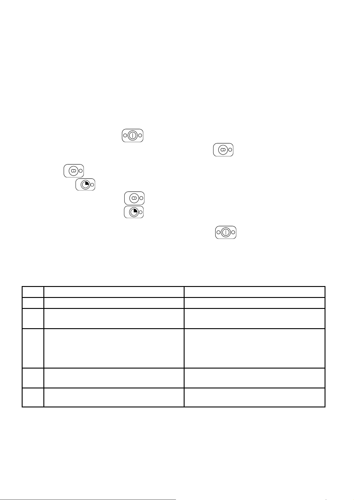
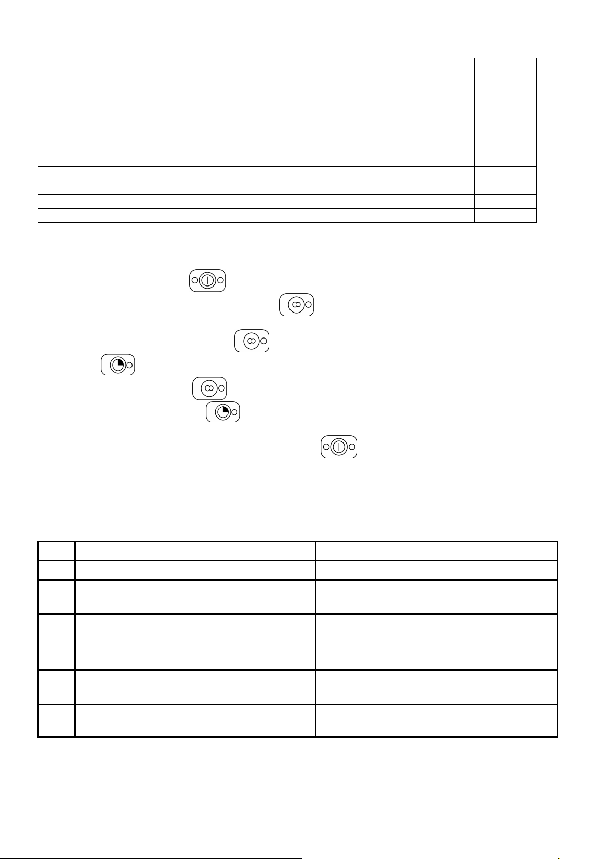
Per entrare nel menu fabbrica occorre seguire la seguente procedura:
1) spegnere la macchina con il tasto
2) entro 6 secondi dallo spegnimento macchina premere 7 volte il tasto
Al termine dei 6 secondi sul display appare appare la scritta “ P0”.
3) Con il tasto
4) Premere il tasto
5) modificare il parametro con il tasto
6) confermare la modifica con il tasto
7) selezionare, allo stesso modo, altri parametri da modificare e modificarli come descritto sopra
8) Dopo aver impostato tutti i parametri della macchina, premere il tasto
selezionare il parametro da modificare
per visualizzare sul display il parametro selezionato
per uscire.
7 ANOMALIE VISUALIZZATE A DISPLAY
La lavastoviglie è in grado di segnalare una serie di malfunzionamenti evidenziati sul display.
Dopo avere spento e riacceso la macchina, se il problema persiste agire come sotto indicato:
E1
E2
Guasto sonda boiler Sostituire
Guasto sonda vasca Sostituire
E3
E6
E7
E8
Timeout carico acqua ( la durata del carico acqua
ha superato il tempo impostato in P9
Anomalia scarico. Al termine della fase di scarico
la cpu rileva ancora acqua in vasca. Puo’ essere
dovuto a:
Timeout vasca 30 minuti
Timeout boiler 15 minuti
Verifica elettrovalvola – Verificare che il rubinetto
dell’acqua sia aperto
guasto pompa scarico
otturazione tubo scarico
guasto pressostato vasca
tempo ciclo di scarico ( P0 ) impostato troppo
basso
Verifica termostato vasca e termostato boiler
Controllo sonde invertite
Verifica termostato vasca e termostato boiler
Controllo sonde invertite
8
8 ISTRUZIONI PER L’UTENTE
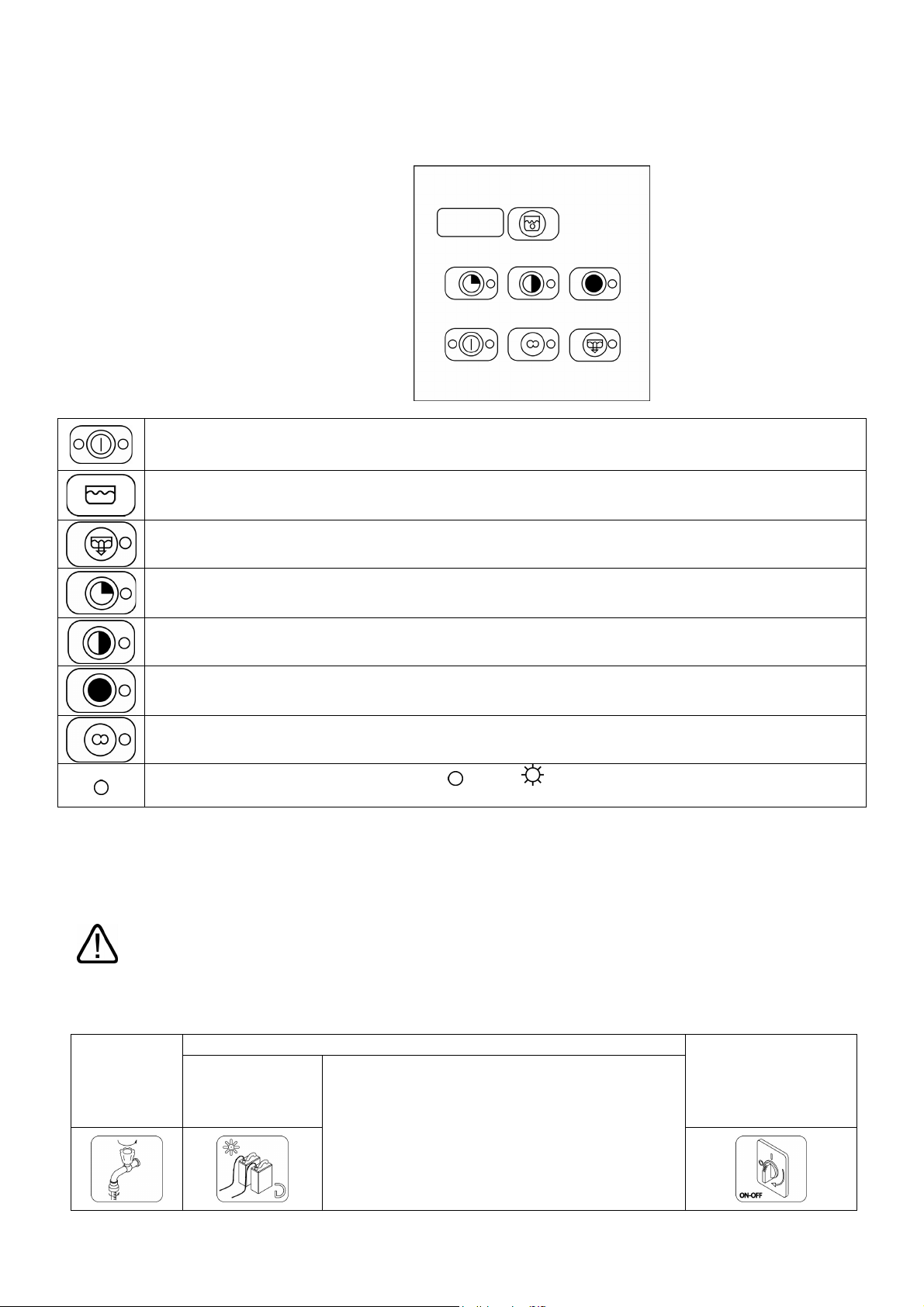
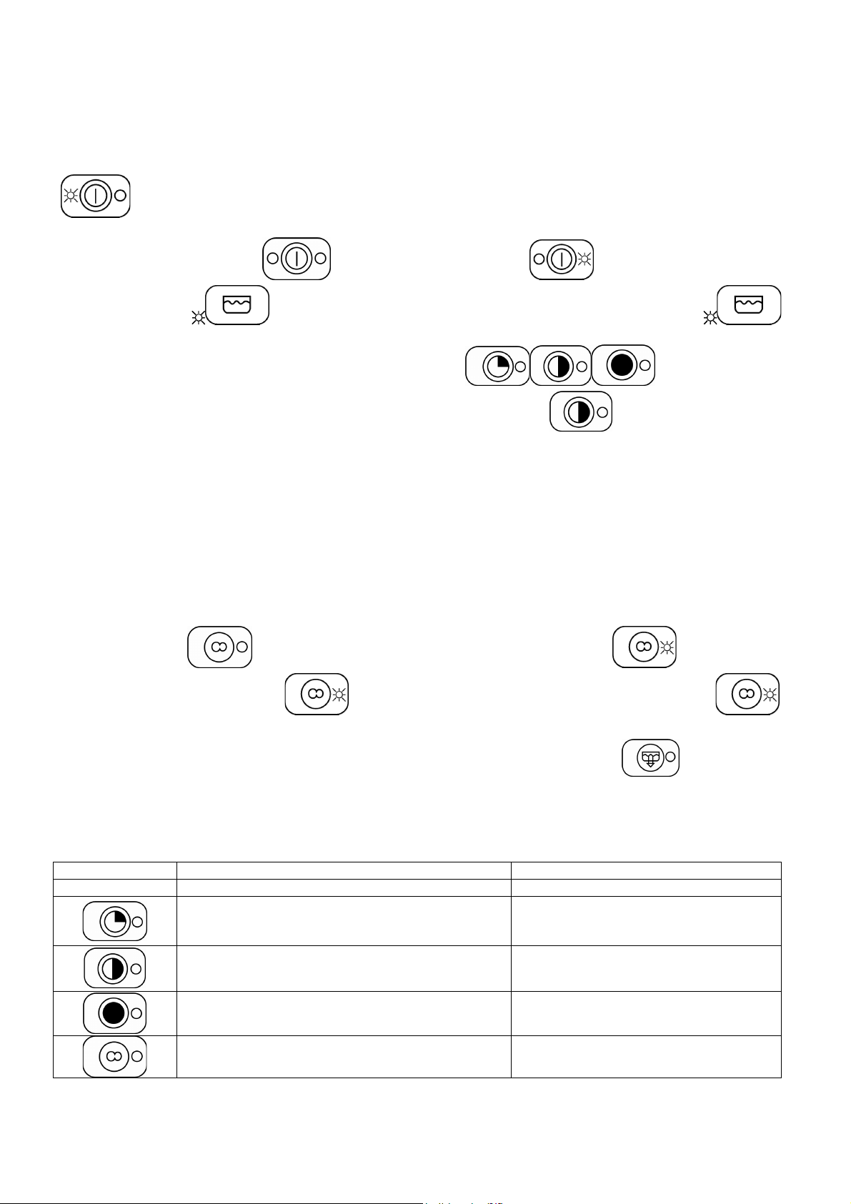
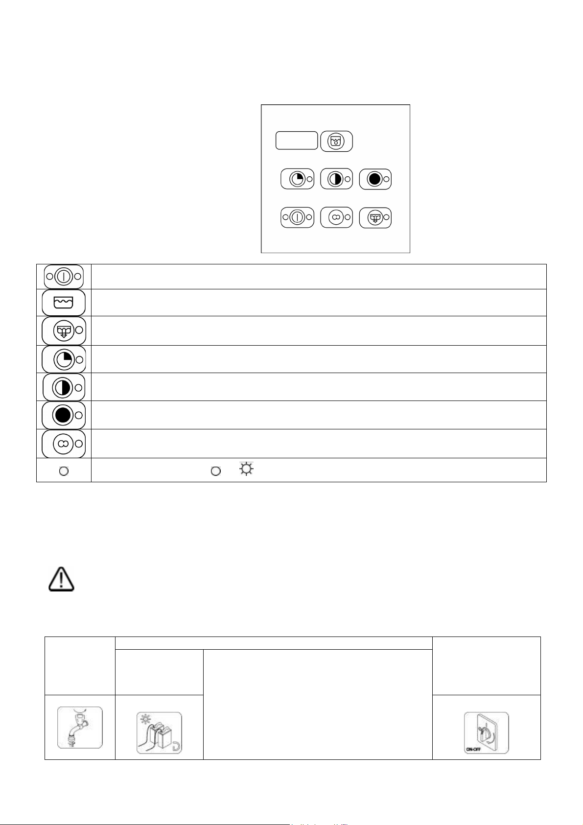
8.1 Pannello comandi
Pulsante on off
Simbolo riempimento vasca
Pulsante svuotamento boiler
Ciclo lavaggio breve
Ciclo lavaggio medio
Ciclo lavaggio lungo
Ciclo lavaggio continuo
Led funzioni: Rappresentazione dei led:
spento; acceso
8.2 Prima del lavaggio
Usare solamente detergenti e brillantanti per lavastoviglie industriali.
Non utilizzare detergenti previsti per il lavaggio a mano.
Consigliamo l’utilizzo di prodotti appositamente studiati per questa lavastoviglie.
Durante il rabbocco dei serbatoi fare attenzione a non scambiare i prodotti, questo potrebbe provocare
malfunzionamenti e danni alla lavastoviglie.
Non mescolare detergenti diversi, si danneggerebbe il dispositivo dosatore.
I detergenti per lavastoviglie industriali possono provocare gravi irritazioni. Rispettare attentamente le istruzioni
del produttore di detersivo riportate sulla confezione.
Aprire il
rubinetto di
rete
dell’acqua
(utenza).
Il livello di
detergente e
brillantante nei
contenitori.
Il corretto posizionamento dei filtri, la rotazione
degli irroratori, l’assenza di corpi estranei nella
Verificare:
lavastoviglie.
Inserire l’interruttore
generale (utenza), sul
display compare
“OFF”.
9
8.3 PRIMO UTILIZZO GIORNALIERO (vasca e boiler vuoti)
Azionare l’ interruttore a muro,si accenderanno due puntini luminosi sul dispaly; il led a sinistra dell’interruttore
si illuminerà di rosso per segnalare macchina in tensione; mettere il troppo pieno e chiudere la capot.
Premere l’ interruttore generale
inizia il carico; Il led
Selezionare il tempo di lavaggio desiderato agendo sui selettori
che al primo avvio la macchina si posiziona automaticamente sul ciclo medio
Per il ciclo selezionato si illumina il led verde relativo. Durante la fase di lavaggio il led lampeggia fino la fine del
ciclo, per ritornare poi verde fisso.
Per l’avvio del ciclo aprire la capot, inserire il cestello e chiudere la capot; il led selezionato inizierà a lampeggiare
per poi rimanere fisso al termine del ciclo completo. Il display inizierà a segnalare le temperature di lavaggio o di
risciacquo in base alla funzione in corso della macchina.
N.B. se la macchina è predisposta con attesa risciacquo il lavaggio continuerà fino al raggiungimento della
temperatura di risciacquo programmata dopo di chè terminerà il suo ciclo.
Per il ciclo continuo
comincerà a lampeggiare e a carico terminato diventerà fisso verde .
dopo averlo selezionato comincerà a lampeggiare il led , per
, il led a destra dell’interruttore diventa verde e la macchina
tenendo presente
.
interromperlo premere nuovamente
sarà illuminato verde fisso.
Per i modelli con pompa di scarico a fine lavoro togliere il troppo pieno e tenere premuto
all’accensione del led inizierà lo scarico che terminerà allo spegnimento automatico della macchina.
e inizierà il risciacquo che terminerà il ciclo quando il led ,
per 4 secondi,
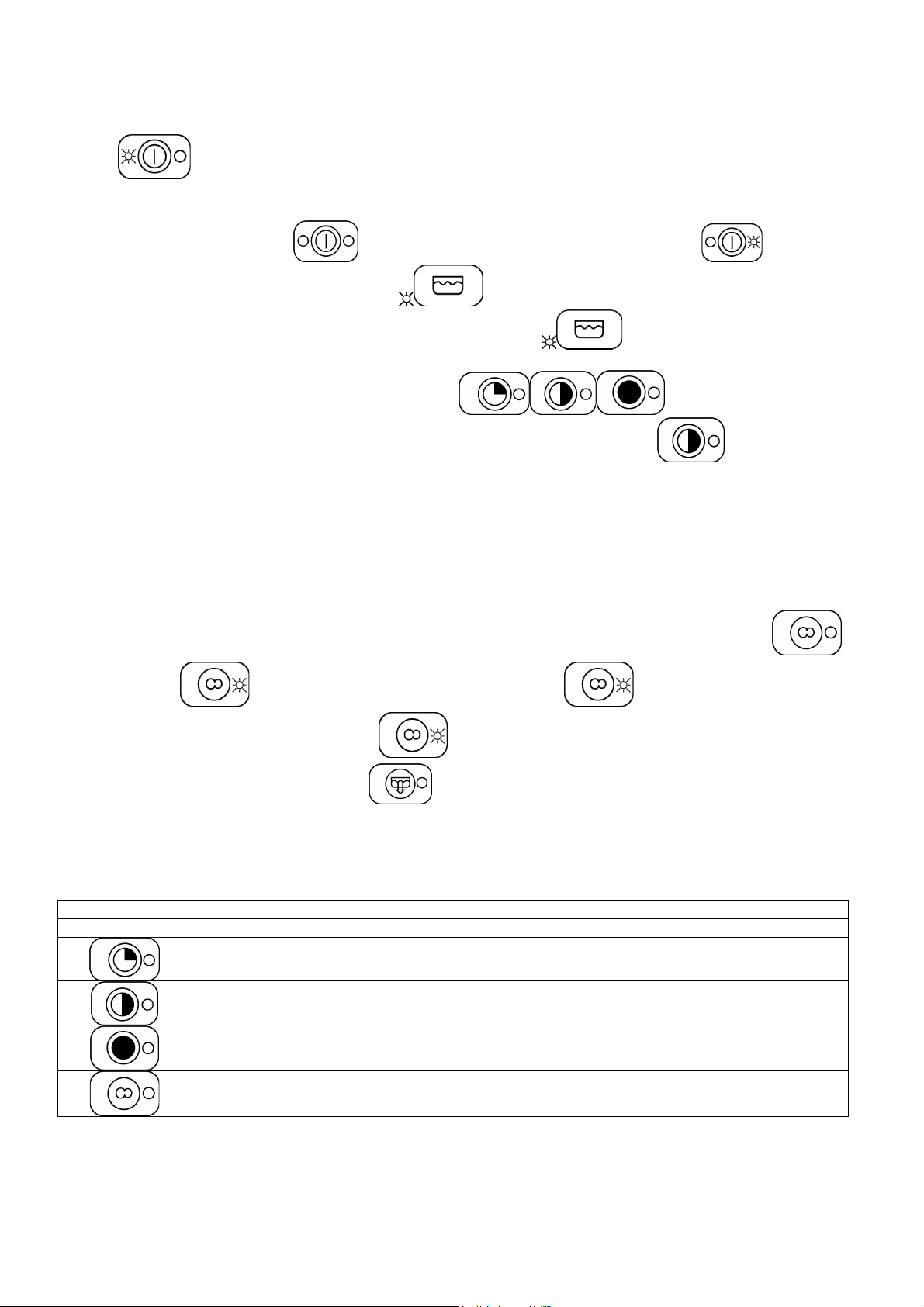
9 SCELTA DEL PROGRAMMA
PROGRAMMA TIPOLOGIA DI SPORCO DURATA (*)
Bicchieri Breve circa 1’ 15”
Bicchieri, tazzine, piatti poco sporchi Media circa 2’
Posate e piatti molto sporchi Lunga circa 3’
Stoviglie particolarmente sporche Continua da 0 a 10’
10
(*) La durata cicli sopraindicata si riferisce ad allacciamento trifase, con alimentazione ad acqua calda a
50°C.
In caso di alimentazione ad acqua fredda la durata cicli potrebbe aumentare in relazione alla temperatura
dell’acqua in ingresso.
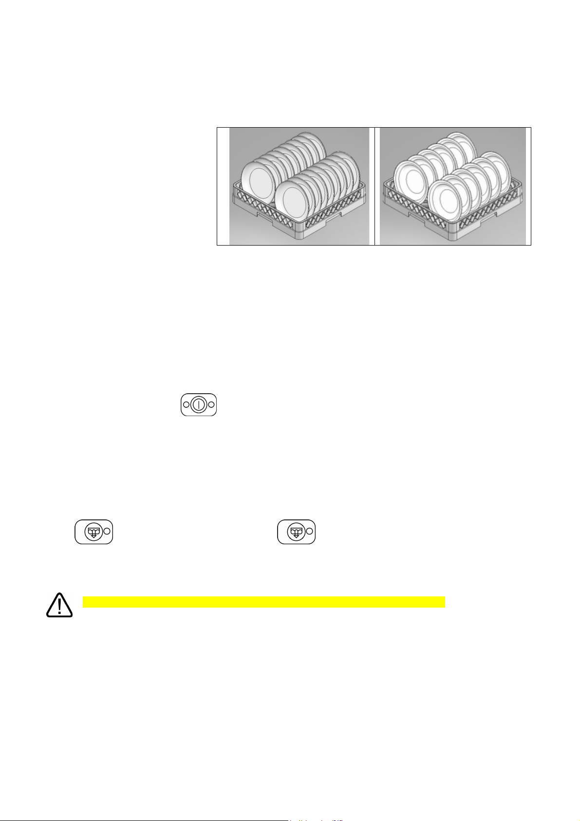
CARICO DELLE STOVIGLIE
Piatti
Il cesto può contenere
12 piatti fondi o 18 piatti piani.
Asportare dai piatti i residui solidi
(ossa, bucce, noccioli, ecc.); lasciare
preventivamente in ammollo in acqua
fredda piatti con residui secchi di
formaggio, uovo……ecc.
Bicchieri
Posizionare i bicchieri rivolti verso il basso.
Posate
Utilizzare l’apposito/i cestino. Disporre le posate alla rinfusa preferibilmente con il manico rivolto verso il basso,
facendo attenzione a non ferirsi con i rebbi delle forchette e le lame dei coltelli.
Scarico totale a fine giornata
Al termine delle operazioni di lavaggio comportarsi come segue:
- portare l'interruttore generale
- disinserire l'interruttore generale a muro;
- chiudere il rubinetto d'alimentazione acqua;
- togliere troppopieno (la macchina inizia a scaricare) ;
- a macchina scarica togliere filtro ;
- lavare l'interno della vasca e i filtri con prodotti idonei;
- ricollocare filtro e troppopieno nelle rispettive sedi.
Per i modelli con pompa di scarico (optional) a fine lavoro togliere il troppo pieno e tenere premuto il pulsante di
scarico
automatico della macchina.
Dopo uno scarico totale si consiglia la pulizia dei filtri come viene spiegato al paragrafo precedente.
per 4 secondi, all’accensione del led inizierà lo scarico che terminerà allo spegnimento
Non spegnere la lavastoviglie con acqua in vasca, eseguire sempre lo scarico.
sulla posizione "OFF";
10 MANUTENZIONE E PULIZIA
Nonostante non sia richiesta una particolare manutenzione programmata consigliamo di fare controllare la
lavastoviglie da un tecnico specializzato due volte l’anno.
N.B: danneggiamenti intenzionali o derivanti da incuria, negligenza, dal mancato rispetto delle prescrizioni,
istruzioni e norme o da collegamenti errati, non sono da ritenersi responsabilità del costruttore.
10.1 Pulizia quotidiana
La lavastoviglie risponde al grado di protezione IPX4, ma è vietato utilizzare getti d’acqua diretti per la pulizia.
11
Pulizia del filtro durante la giornata
E’ consigliato, in caso di utilizzo particolarmente gravoso, effettuare ogni 30-40 cicli la pulizia del filtro, mantenendo
la macchina in condizioni operative; per fare questo eseguire lo “scarico parziale vasca”.
Rimuovere i filtri (è sufficiente sollevarli dalla loro sede come indicato in
figura), facendo attenzione che residui grossolani non cadano nel pozzetto
sotto i filtri, pulirli dai residui e risciacquarli abbondantemente, reinserendoli
poi correttamente; non intervenire con oggetti appuntiti o taglienti.
Pulire eventuali incrostazioni di calcare per evitare accumuli;
- Pulire accuratamente e frequentemente le superfici con uno
straccio umido; utilizzare detergenti neutri, non abrasivi, non
contenenti sostanze a base di cloro, prodotti che corrodono e
danneggiano l’acciaio inox.
Non utilizzare i prodotti sopra elencati nemmeno per pulire il pavimento sotto la lavastoviglie o nelle vicinanze,
per evitare che vapori o gocce possano produrre danni alle superfici in acciaio.
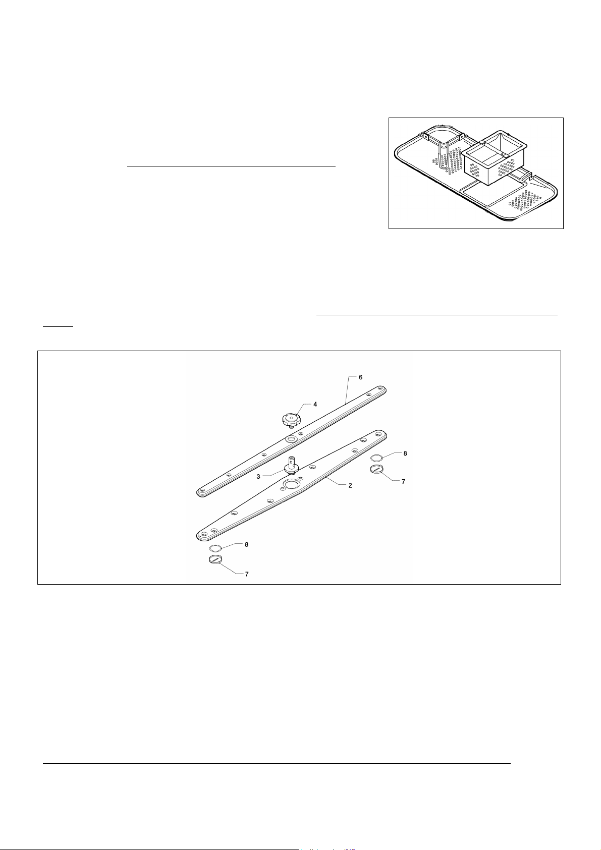
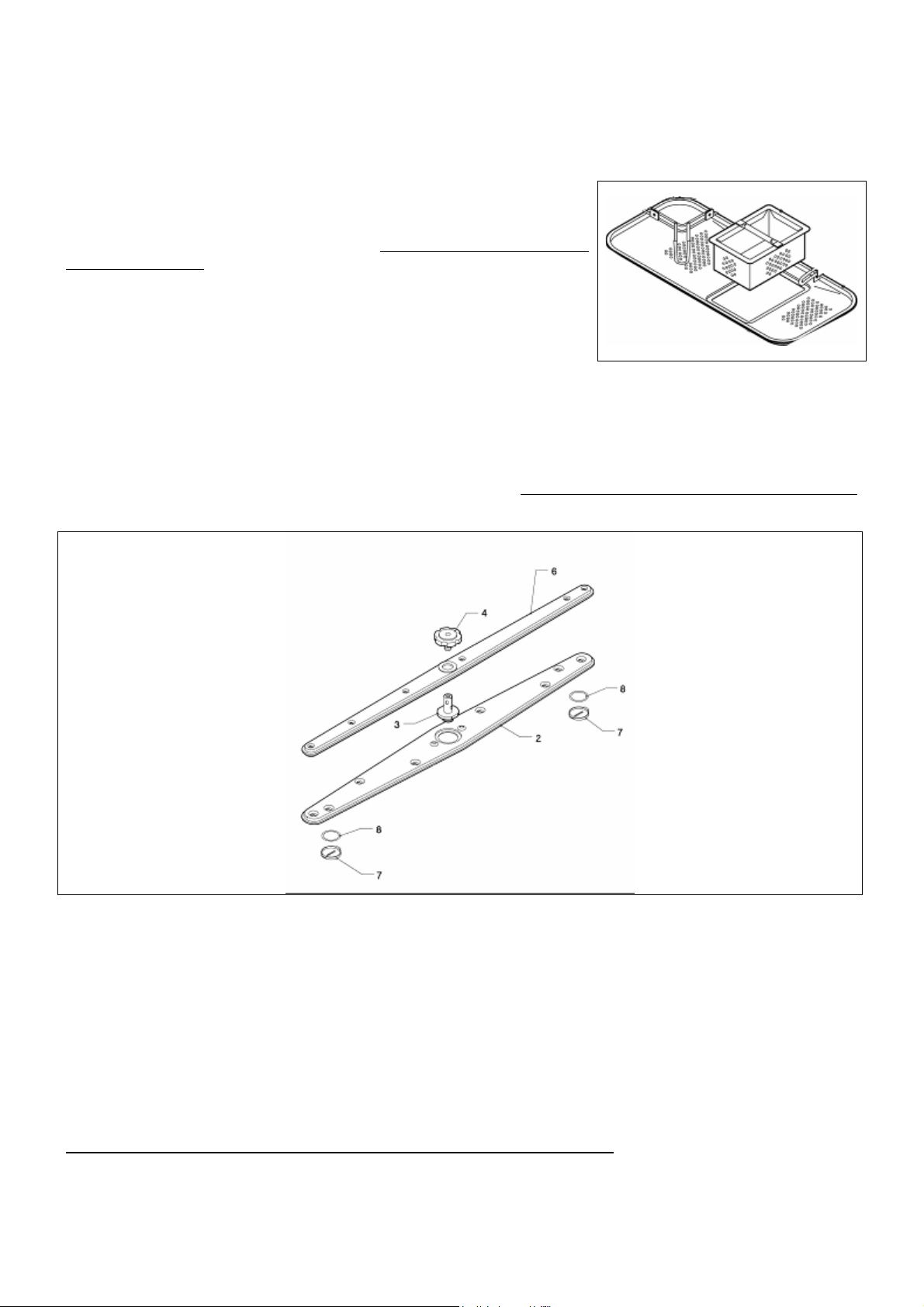
10.2 Controlli periodici
Smontare gli irroratori (inferiore e superiore 2-4), svitando la vite centrale (4); svitare i tappi alle due estremità degli
irroratori di lavaggio (7).
Pulire i fori e gli ugelli sotto un getto d’acqua corrente pulita, non intervenire con attrezzi che potrebbero provocare
danni. Rimontare gli irroratori con cura.
Pulire esternamente la macchina con un panno umido e sapone neutro risciacquando ed asciugando
attentamente.
10.3 Sosta prolungata
Se si prevede di non utilizzare la lavastoviglie per un periodo di tempo piuttosto lungo, è necessario eseguire lo
svuotamento del dispositivo erogazione di detergente e brillantante per evitare cristallizzazioni e danni
alle pompe: Togliere i tubi di pescaggio dai contenitori del detergente e brillantante ed immergerli in un
contenitore contenente di acqua pulita, eseguire alcuni cicli di lavaggio, eseguire scarico completo.
Infine disinserire l’interruttore generale, chiudere il rubinetto d’entrata acqua, I tubi di pescaggio detergente e
brillantante andranno nuovamente inseriti nei contenitori al momento della messa in funzione, facendo attenzione
a non invertirli (tubo rosso = detergente; tubo trasparente = brillantante).
Non lasciare l' apparecchio inattivo acceso ed inutilizzato per periodi di tempo più o meno lunghi.
12
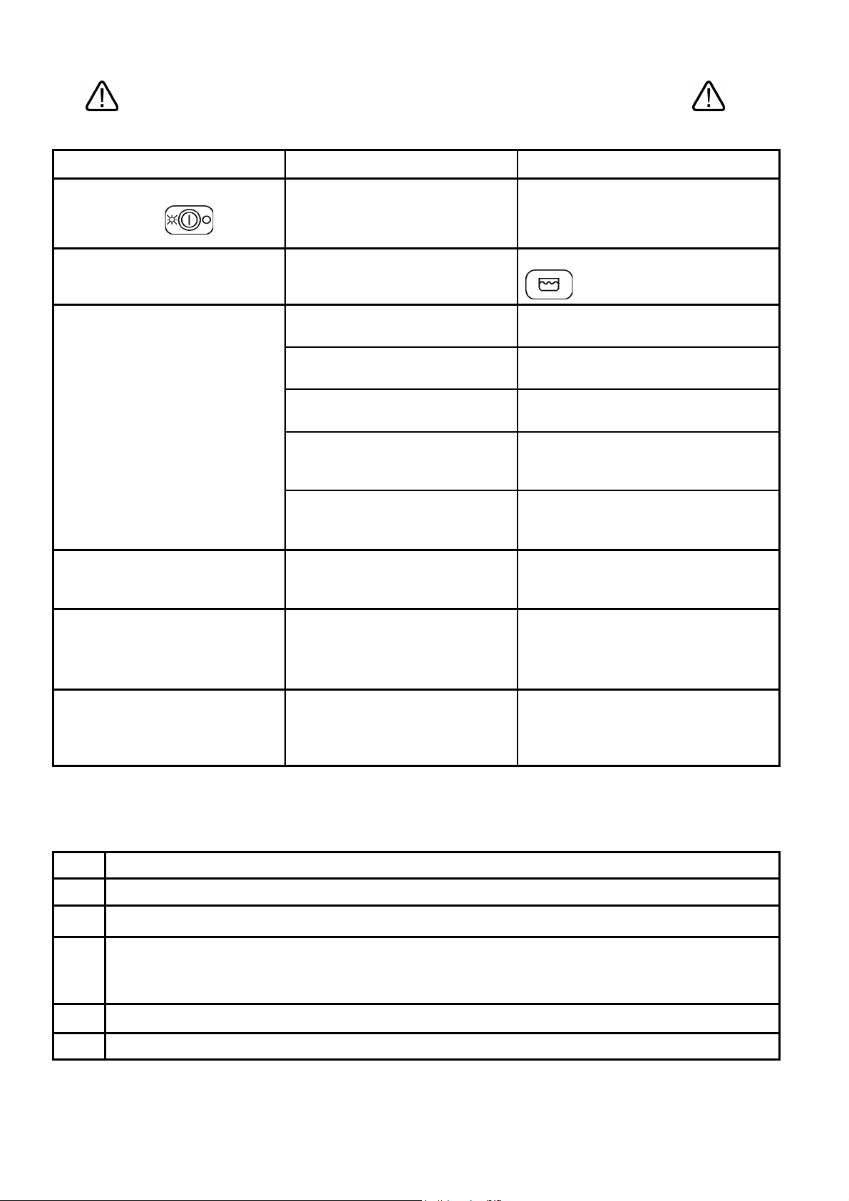
PROBLEMA
11 PROBLEMI ED ANOMALIE (UTENTE)
POSSIBILE CAUSA
POSSIBILE RIMEDIO
NON SI ACCENDE LA
SPIA DI RETE
IL PROGRAMMA DI LAVAGGIO
NON SI AVVIA
RISULTATI DI LAVAGGIO
SCADENTI
RISCIACQUO INSUFFICIENTE
Manca tensione di rete
Il riempimento della lavastoviglie
non è ancora terminato.
Fori di lavaggio degli irroratori
intasati o incrostati
Detergente o brillantante
insufficiente o non adeguato
Piatti /bicchieri mal posizionati
Bassa temperatura di lavaggio
Ciclo impostato inadeguato
Ugelli irroratori intasati
Boiler incrostato di calcare
Verificare connessione alla rete
elettrica.
Attendere l’accensione del led
Smontare e pulire irroratori
(10.2 Controlli periodici)
Verificare tipo e quantità di detergente.
Disporre adeguatamente
piatti/bicchieri.
Verificare temperatura visualizzata sul
display, se inferiore ai 50° chiamare
Assistenza.
Aumentare durata ciclo di lavaggio, in
particolare se molto sporco o
parzialmente essiccato.
Verificare pulizia ugelli e se
l’addolcitore eventualmente montato
funziona correttamente.
BICCHIERI E POSATE
MACCHIATI
Brillantante inadeguato o non
erogato correttamente.
Durezza acqua superiore a 12°dF
o molti sali disciolti
Verificare contenitore brillantante e se
adeguato al tipo di acqua di rete. Se il
problema permane contattare
assistenza.
Verificare che il tubo e lo scarico della
PRESENZA DI ACQUA IN
VASCA DOPO LO SCARICO
Tubo di scarico mal posizionato o
parzialmente ostruito
lavastoviglie non siano ostruiti e che lo
scarico non sia posizionato troppo in
alto; vedi schema di collegamento.
12 ANOMALIE VISUALIZZATE A DISPLAY (UTENTE)
Dopo aver spento e riacceso la macchina se il problema persiste contattare l' assistenza tecnica comunicando il
tipo di errore a display :
E1
E2
E3
E6
E7
Guasto sonda boiler
Guasto sonda vasca
Timeout carico acqua ( la durata del carico acqua ha superato il tempo impostato )
Anomalia scarico. Al termine della fase di scarico la cpu rileva ancora acqua in vasca.
Puo’ essere dovuto a: guasto pompa scarico (se presente), otturazione tubo scarico, guasto pressostato
vasca, tempo ciclo di scarico impostato troppo basso
Timeout vasca 30 minuti
E8
Timeout boiler 15 minuti
13
1 Safety and usage instructions
2 Technical characteristics
3 Installation and positioning
4 INSTALLER – TECHNICAL ASSISTANT INSTRUCTIONS
5 First startup
6 Settings
7 Screen-displayed anomalies (technical)
8 USER INSTRUCTIONS
9 Program selection
10 Maintenance and cleaning
11 Problems and anomalies (user)
12 Screen-displayed anomalies (user)
Thank you for having chosen this product.
We recommend that you read all of the instructions contained in the manual attentively in order to become
familiar with the most suitable conditions for the correct use of the dishwasher.
TECHNICAL INSTRUCTIONS:
Are intended for qualified personnel who will perform the installation, the setup, the testing
and eventual assistance operations.
USER INSTRUCTIONS:
Indicate the recommended usage, the command descriptions and the proper cleaning and
maintenance operations for the dishwasher.
2
1 Safety and usage instructions
THIS MANUAL CONSTITUTES AN INTEGRAL PART OF THE DISHWASHER; IT MUST
NECESSARILY BE STORED INTEGRAL AND TOGETHER WITH THE APPARATUS.
THE DISHWASHER IS INTENDED EXCLUSIVELY FOR PROFESSIONAL USE AND MUST BE USED BY
COMPETENT PERSONNEL. IT IS DESIGNED TO WASH DISHES (PLATES, CUPS, BOWLS, BAKING
PANS, SILVERWARE) AND SIMILAR ITEMS FROM THE GASTRONOMY AND THE COLLECTIVE
RESTAURANT INDUSTRIES. IT CONFORMS TO THE INTERNATIONAL ELECTRIC AND MECHANICAL
SAFETY NORMS (CEI-EN-IEC 60335-2-58/61770) AND ELECTROMAGNETIC COMPATIBILITY NORMS
(CEI-IEC-EN 55014-1/-2, 61000-3;4, 50366).
THE MANUFACTURER DECLINES ANY RESPONSABILITY FOR DAMAGE TO PERSONS OR THINGS
CAUSED BY NON-OBSERVANCE OF THE INSTRUCTIONS PRESENT IN THE MANUAL, BY INCORRECT
USE, BY TAMPERING EVEN WITH A SINGLE PART OF THE APPARATUS AND BY USE OF NONORIGINAL REPLACEMENT PARTS.
THIS APPARATUS IS MARKED IN CONFORMITY TO THE EUROPEAN DIRECTIVE 2002/96/EC, WASTE
ELECTRICAL AND ELECTRONIC EQUIPMENT (WEE).
BY ENSURING THAT THIS PRODUCT BE DISPOSED OF IN A CORRECT MANNER, THE USER
CONTRIBUTES TO THE PREVENTION OF POTENTIALLY NEGATIVE ENVIRONMENTAL AND HEALTH
CONSEQUENCES.
THE
THAT THIS PRODUCT MUST NOT BE TREATED AS DOMESTIC WASTE, BUT MUST BE TAKEN TO A
SUITABLE COLLECTION DEPOT FOR THE RECYCLING OF ELECTRIC AND ELECTRONIC APPARATUS.
DISPOSE OF THE APPARATUS ACCORDING TO THE LOCAL WASTE DISPOSAL NORMS.
FOR MORE INFORMATION ON THE TREATMENT, RECOVERY AND RECYCLING OF THIS PRODUCT,
CONTACT YOUR COMPETENT LOCAL AUTHORITY, YOUR DOMESTIC WASTE DISPOSAL SERVICE OR
THE STORE IN WHICH THE PRODUCT WAS PURCHASED.
THE POSITIONING, CONNECTIONS, SETUP AND TROUBLESHOOTING, AND THE
SUBSTITUTION OF THE POWER CABLE MUST BE PERFORMED BY QUALIFIED
PERSONNEL.
THE ELECTRICAL GROUNDING OF THE APPARATUS ACCORDING TO THE METHODS
PRESCRIBED BY THE ELECTRICAL SYSTEM’S SAFETY NORMS IS OBBLIGATORY.
SYMBOL ON THE PRODUCT, OR UPON ITS ACCOMPANYING DOCUMENTATION, INDICATES
DO NOT INSERT SOLVENTS SUCH AS ALCOHOL OR TURPENTINE WHICH COULD
PROVOKE EXPLOSIONS. DO NOT INSERT DISHES WITH RESIDUES OF ASH, WAX OR
VARNISH.
NEVER USE THE DISHWASHER OR ITS PARTS AS A STEP-LADDER, SUPPORT OR BRACE
FOR PERSONS, THINGS OR ANIMALS.
LEANING OR SITTING UPON THE DISHWASHER’S OPEN DOOR COULD CAUSE IT TO TIP,
WITH CONSEQUENT PERSONAL DANGER.
DO NOT LEAVE THE DISHWASHER’S DOOR OPEN IN ORDER TO AVOID TRIPPING UPON
IT.
DO NOT DRINK THE RESIDUAL WATER EVENTUALLY PRESENT IN THE DISHES OR IN THE
DISHWASHER AFTER A WASH CYCLE.
THE APPARATUS IS NOT ADAPTED FOR USE BY MINORS AND PEOPLE WITH REDUCED
PHYSICAL, SENSORIAL OR MENTAL CAPABILITIES WITHOUT EXPERIENCE OR
FAMILIARITY WITH THE DEVICE. THE USE OF THE APPARATUS IS PERMITTED TO THESE
PEOPLE ONLY UNDER THE SUPERVISION OF A PERSON IN CHARGE OF THEIR SAFETY.
3
2 Technical characteristics
Voltage
Frequenza
V
Hz 50 50 50
AGB672
AGB669
400V/3+N
230V/1
AGB666
AGB670
400V/3+N
230V/1
Total power kW 6,75 7,1 10,75
AGB664
400V/3+N
230V/1
Boiler element power
Tank element power
Wash pump power
Water supply pressure
Water supply temperature
Water supply hardness
Rinse cycle water consumption
Boiler capacity
Tank capacity
Standard cycle duration with water supply at 50°C
Noise level
Protection rating
Net weight
Power cable type
kW 6 6 10
kW 3 3 3
kW 0,75 1,1 0,75
kPa 200-400 200-400 200-400
°C 50 – 60 50 – 60 15 – 30
°dF 7 – 12 7 – 12 7 – 12
l 3,5 3,5 3,5
l 9 9 12
l 28 35 28
s 60/120/180/C 60/120/180/C 60/120/180/C
dB(A) 67 67 67
IPX 4 4 4
kg 115 123 118
◄HAR► H05VV-F H05VV-F H05VV-F
Electrical Scheme – voltage regulation
400/3 Volt
RST RST
Wash Pump Boiler Resistance
230/3 Volt
TRB
TRB
400/3 Volt
230/3 Volt
4

3 Installation and positioning
INSTALLATION and POSITIONING
Bring the dishwasher to its installation location, remove its packaging and verify the integrity of the apparatus
and of the components. If damaged, written notification must be sent to the transporter.
The packaging elements (plastic bags, polystyrene foam, nails, etc) must not be left within reach of children
and domestic animals as they are a potential source of danger.
All of the materials used for packaging are compatible with the environment. They may be safely preserved, or
may be disposed of at an appropriate waste disposal facility.
The components in plastic material subject to eventual disposal through recycling are marked in the following
manner:
PE polyethylene: external wrapping, instructions bag, protection bags.
PP polypropylene: bands.
PS polystyrene foam: protective corners, packaging cover.
The wood and cardboard components can be disposed of by respecting the norms in vigor.
When disposing of the product, avoid leaving it in the environment; its disposal must respect the norms in vigor.
All of the metallic parts are in stainless steel and are detachable.
The plastic parts are marked with the symbol of the relative material.
POSITIONING:
Warning:
must answer to the norms in vigor.
The manufacturer declines any responsibility for direct damages to persons of things deriving from lack of
respect for the said norms.
Prior to installation verify that objects and materials which could be damaged by aqueous vapor or by spray
from washing solutions are not in the vicinity, or are adequately protected.
Position the dishwasher in the desired position and remove the protective wrapping.
Level the dishwasher (with the help of a level) on its four feet, regulating them in such a way so as to
guarantee stability; any alternate solution must be approved by the manufacturer.
the internal system and the locations in which communal apparatus are to be installed,
4 INSTALLER – TECHNICAL ASSISTANT
INSTRUCTIONS
Water and drain connection:
The water tubes and the electrical power cable stick out from the back of the machine. Connect the water
supply tube to a ¾” threaded gas outlet.
Use only new tubes for the connection to the water supply; old or used tubes must not be utilized.
The dynamic supply pressure must be between 2 and 4 bar; if the pressure is higher, a pressure reducer
must be installed.
It is indispensable to install a general faucet on the supply water input tubing; the faucet must be accessible
after installation has been completed. Do not install the faucet behind the dishwasher.
The declared cycle durations refer to a 50° hot water supply.
Where a cold water supply is used, the duration of the cycle could increase in relation to the input water
temperature since the dishwasher is equipped with a constant temperature and pressure rinse system.
Drain:
Every dishwasher comes equipped with a drain connection tube; this is prescribed to be at floor level, with a
trap drain.
5
Caution: make sure that the supply and drain tubes are not bent, restricted or crushed after
installation.
4.1 Electrical connection
The dishwasher’s electrical connection and that of eventual supplementary apparatus is to be
entrusted to authorized and qualified personnel, with respect to the norms in vigor; observe also the
technical regulations for the connections.
The total power installed is given upon the apparatus’ technical data label.
Other apparatus must not be protected along with the dishwasher.
The user must provide for the installation, according to the norms in vigor, of a main electrical power
switch and of a differential switch compatible with the machine’s characteristics.
These switches must be installed near the dishwasher, be easily accessible after installation and
guarantee complete disconnection from the electrical supply in category III overvoltage conditions.
Caution!!!
The dishwasher is free of electrical current only when the main switch is off.
- Connect the apparatus to the usage equalizer. The
back of the machine.
- The protection conductor (PE) is yellow-green in color, the neutral conductor (N) is blue and the
phase conductors (L1, L2, L3) are black, gray and brown.
clamp for the connection is located at the lower
5 FIRST STARTUP
FIRST STARTUP
The electrical protection system must be subjected to a functional test before use. The installation must be
performed and/or verified by the authorized reseller who will be responsible for the first startup and the
instructions relative to the dishwasher’s operation.
PREPARATION FOR USE
Important:
The rinse-aid metering unit comes equipped in all models
while the detergent metering unit comes equipped in only
some models.
If both metering units are present position the external
detergent and rinse-aid containers and insert their
respective suction tubes located at the back of the machine.
Red tube: detergent
Transparent tube: rinse-aid
Before inserting the tubes in the containers apply the weight
(necessary to keep the tube at the bottom of the container)
and the filter as indicated in the diagram.
For adjustments, use the adjustment screws indicated in the diagram. It is
recommended that adjustments be performed by personnel from the companies who
have supplied the detergent products.
If the detergent metering unit did not come pre-installed it can be installed at a later
time by ordering the relative KIT.
Alternatively, an external metering unit can be connected by means of an electrical
connection with a 2x0.5 mm type H05 RN-F cable. This cable must be inserted through
the passage indicated in the TECHNICAL CHARACTERISTICS scheme and
connected in accordance with the electrical scheme furnished with the dishwasher.
The metering unit must be of 230V/50Hz with a maximum absorbed power of 15W.
Connect the detergent metering unit to the dishwasher through the red tube cited above.
.
6
6 TRONIC MODEL SETTINGS ( Installer )
SETTINGS
During the first startup, arrange for the setup or the adjustment of the functions/parameters indicated
hereafter:
POWER SUPPLY : 200 – 250 VAC.
POWER CONSUMED : 4 VA
OPERATIONAL TEMPERATURE: 0 / 60 °C
OPERATIONAL HUMIDITY: max 90 % without condensation
NORMS: The control unit is designed and manufactured in observance of the
European norms in vigor regarding electrical safety and electromagnetic compatibility.
Particularly the following:
EN 61000-6-3 : Emissions for residential and commercial environments
EN 61000-6-2 : Immunity for industrial environments
EN 61000-4-11 : Immunity to supply micro-interruptions
EN 60335-1 : Low voltage safety directive
ZERO CROSSING : The relay which powers the tank’s electrical resistance is equipped with the “ zero crossing “
function which synchronizes the switching of this relay, both in closing and in opening, with the voltage supply’s
passing to zero, both for 50 Hz and 60 Hz frequencies. In this manner, use of the relay’s contacts is significantly
reduced.
Clamp Connection for top-loading models
1 – 2 Control Unit Power Supply, 230 VAC
3 – 4 Boiler temperature sensor
5 – 6 Tank temperature sensor
10 Break-tank pressostat
11 Reserve input
12 Micro hood
13 Tank pressostat, closed over level
14 Common inputs
15 Boiler resistance remote control switch coil
16 Tank resistance, max. 10 Amp.
17 18 18 B.TANK Rinse pump (machine type 4)
19 Wash pump ( max. 1 HP )
20 Rinse electrovalve + pressure increase pump
21 Drain pump ( max. 0.75 HP ) Optional
22 Output power supplies, 230 VAC phase
Parameter Description Range Preset
P0 Drain cycle time 1-5’ 1
P1 Boiler temperature 60-95°C 82°C
P2 Tank temperature 40-65°C 55°C
P3 Rinse duration 10-40’’ 13”
P4 Boiler stop option YES/NO 0 NO
7
Machine type
1 = brief, continuous wash (maximum 10’)
2 = brief, medium, long, continuous wash (maximum 10’)
P5
P6 Drain with overflow option YES/NO 0 NO
P7 Cold rinse option YES/NO 0 NO
P8 Regeneration option YES/NO 0 NO
P9 Maximum water load duration 1-10’ 10
To access the factory menu the following procedure must be followed:
3 = brief and medium wash set to 1
4 = break tank, medium, long and continuous wash
with this configuration the cold rinse option must be set to “0”
5 = with three wash cycles without break tank for top-loading
6 = with three wash cycles with break tank for top-loading
1) Shut the machine off with the
2) Within 6 seconds of machine shutdown press the
At the end of the 6 seconds, the message “ P0” will appear on the screen.
3) Select the parameter to modify with the
4) Press the
5) Modify the parameter with the
6) Confirm the modification with the
7) Select, in the same way, other parameters to be modified and modify them as described above
8) After having set all of the machine’s parameters, press the
button to view the selected parameter on the display
button
button 7 times
button
button
button
button to exit.
7 SCREEN DISPLAYED ANOMALIES
The machine is capable of signaling a series of malfunctions on the display.
If the problem persists after having turned the machine off and then on again, act as indicated below:
E1
E2
Boiler sensor malfunction Substitute
Tank sensor malfunction Substitute
E3
E6
E7
E8
Water loading timeout ( the water loading duration
has exceeded the time set in P9 )
Draining anomaly. At the end of the draining phase
the CPU still detects water in the Tank. This may
be due to:
30 minute Tank timeout
15 minute boiler timeout
Electrovalve inspection – Verify that the water
faucet is open
Drain pump malfunction
Drain tube blockage
Tank Pressostat malfunction
Drain cycle time ( P0 ) set too low
Inspect the Tank and boiler thermostats
Check for inverted sensors
Inspect the Tank and boiler thermostats
Check for inverted sensors
8
8.1 Control panel
8 USER INSTRUCTIONS
On Off button
Tank filling symbol
Boiler draining button
Brief wash cycle
Medium wash cycle
Long wash cycle
Continuous wash cycle
Led indicator functions:
off; flashing/on
8.2 Before washing
Use only detergents and rinse-aids for industrial dishwashers.
Do not use detergents intended for hand washing.
It is recommended to use products which were designed especially for this dishwasher.
During the loading of the tanks be careful not to switch products as this could provoke dishwasher
malfunction and damage.
Do not mix different detergents together as this could damage the metering unit.
Detergents for industrial dishwashers can cause serious irritations. Take care to respect the instructions
provided by the detergent manufacturer on the packaging.
Open the
water supply
faucet
(usage).
The levels of
detergent and
rinse-aid in the
containers.
The correct positioning of the filters, the rotation of
the sprinklers, the absence of foreign objects
Verify:
within the dishwasher.
Turn off the main
switch (usage), “OFF”
appears on the
display.
9
8.3 FIRST DAILY USE (Tank and boiler empty)
Activate the wall switch. Two small illuminated points on the display will turn on; the led indicator on the left of the
switch
overflow and close the hood.
- Press the general power
and the machine begins to fill itself. The
completed it will stop flashing and will remain a steady green
- Select the desired washing time by means of the
that upon first use the machine is positioned automatically on a medium cycle
indicator relative to the selected cycle turns on. The led indicator flashes until the end of the wash cycle,
after which it turns a steady green again. To start the cycle, open the hood, insert the basket and close the
hood; the selected led indicator will begin to flash and will stop flashing at the end of the completed cycle.
- The display will indicate the wash or rinse temperatures based upon the active function of the machine.
Note: if the machine came equipped with rinse delay, the wash will continue until the programmed rinse
will be lit red in order to indicate that the machine is receiving electrical current; Position the
button. The led indicator to the right of the button turns green
led indicator will begin to flash. Once filling has been
selectors, keeping in mind
. The green led
temperature is reached, after which the cycle will terminate. After having selected the continuous cycle
the led indicator
the cycle will terminate once the led indicator
drain pump, remove the overflow and press
turns on, and will terminate with the automatic shutdown of the machine.
will start to flash. To interrupt the cycle press again. The rinse will begin and
becomes a steady green.When finished, for models with a
for 4 seconds. Drainage will begin once the led indicator
,
9 PROGRAM SELECTION
PROGRAM WASH TYPEOLOGY DURATION (*)
Glasses Brief about 1’ 15”
Glasses, cups, very dirty plates Medium about 2’
Silverware and very dirty plates Long about 3’
Particularly dirty dishes Continuous from 0 to 10’
(*)The cycle durations indicated above are based upon a tri-phase connection with a 50°C hot water
supply.
Where a cold water supply is used, the duration of the cycle could increase in relation to the input water
temperature.
10
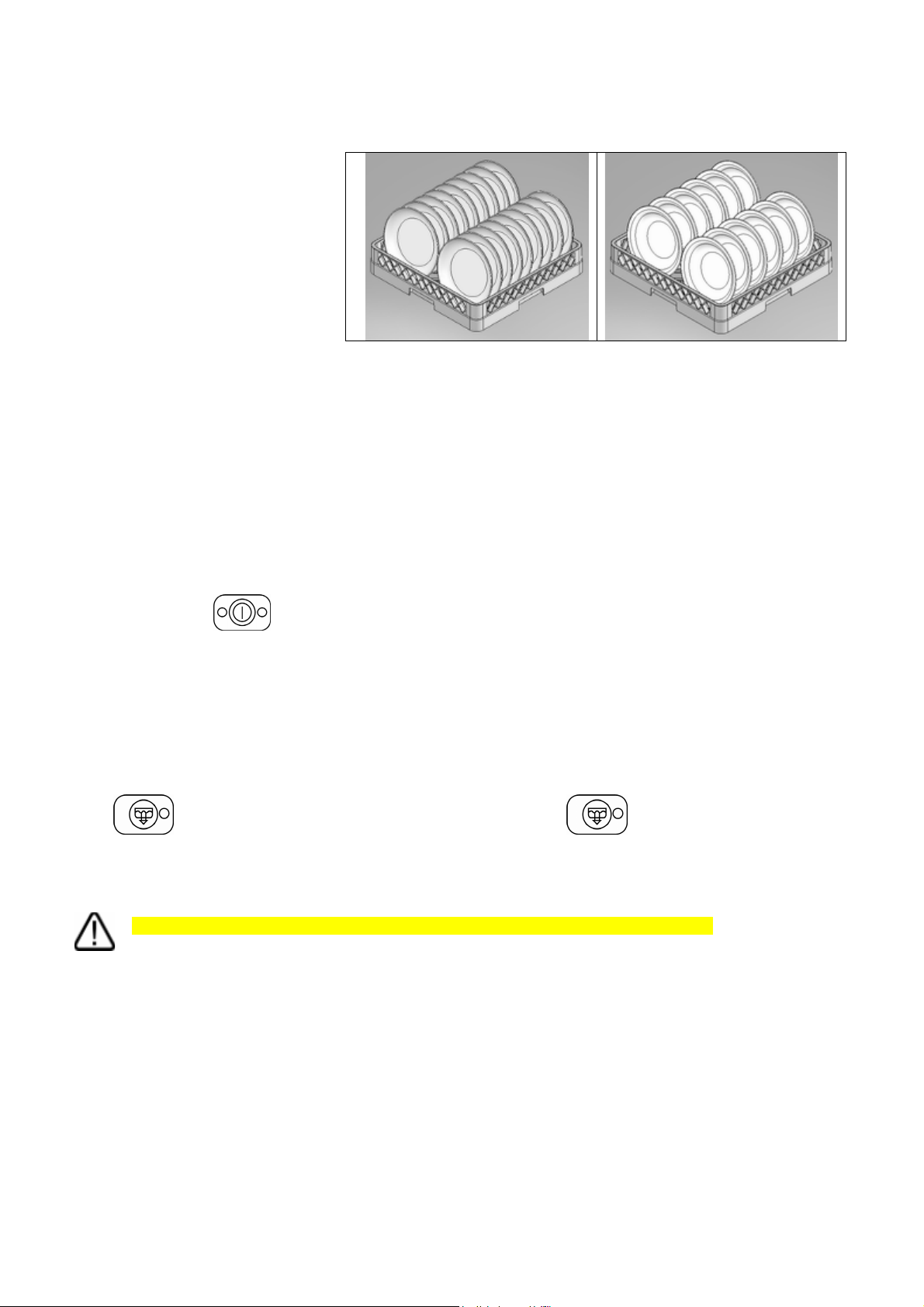
DISH LOADING
Plates
The basket can contain
12 bowls or 18 flat plates.
Remove solid residues from the dishes
(bones, peels, cores, etc.); before
washing, let dishes with residues of
dried-on cheese, egg…… etc. soak in
cold water.
Glasses
Cups should be positioned upside down.
Silverware
Use the appropriate basket(s). It is preferable to arrange large amounts of silverware with the handles facing down,
taking care to avoid injury from fork prongs and knife blades.
Total drainage at the end of the day
When all washing operations have been completed, do the following:
- turn the main switch
- turn off the main wall switch;
- close the water supply faucet;
- remove the overflow (the machine begins to drain) ;
- remove the filter once the machine is empty;
- wash the inside of the Tank and the filters with suitable products;
- reposition the filters and the overflow in their respective lodgings.
At the end of the working day, for models with a drain pump (optional), remove the overflow and press the drain
button
the automatic shutdown of the machine.
The cleaning of the filters is recommended after a complete draining, as described in the previous paragraph.
for 4 seconds. Drainage will begin once the led indicator turns on and will terminate with
Do not turn off the washing machine while the Tank is full. Always drain it first.
to the "OFF" position;
10 MAINTENANCE AND CLEANING
Notwithstanding that special, programmed maintenance is not required, we recommend having the dishwasher
checked by a specialized technician twice a year.
Note: intentional damage or that derived from carelessness, negligence, lack of respect for the regulations,
instructions and norms or erred connections are not to be considered the responsibility of the manufacturer.
10.1 Daily cleaning
The dishwasher has an IPX4 protection rating, but the use of direct streams of water for its cleaning is forbidden.
11
Cleaning of the filter during the day
In case of particularly heavy usage it is recommended to perform a cleaning of the filter every 30-40 wash cycles in
order to maintain the machine in operative conditions; Use “partial Tank draining” in order to perform these
cleanings.
Remove the filters (it is sufficient to lift them out of their lodgings as shown
in the figure), making sure that greasy residues do not fall into the opening
underneath the filters. Clean away the residues and rinse the filters
abundantly before correctly replacing them; Do not utilize pointy or sharp
objects for cleaning.
Be sure to remove eventual hardened calcium deposits in order to avoid
their accumulation;
- Clean the surfaces well and frequently with a damp rag; use neutral,
non-abrasive detergents which do not contain chlorine-based
substances. Corrosive products can damage stainless steel.
In order to avoid drops or vapors damaging the steel surfaces, do not even use the above-indicated products for
the cleaning of the flooring beneath or around the dishwasher.
10.2 Periodic checks
Disassemble the sprinklers (lower and upper 2-4) by removing the central screw (4); unscrew the caps at the two
far ends of the rinsing sprinklers (7).
Clean the holes and the nozzles under a stream of clean water. Do not use utensils which could cause damage.
Carefully reassemble the sprinklers.
Clean the outside of the machine with neutral soap and a damp cloth. Rinse and dry with care.
10.3 Prolonged disuse
If the use of the dishwasher is not foreseen for a relatively long period of time it is necessary to drain the
detergent and rinse-aid dispenser in order to avoid crystallization and pump damage: Remove the suction
tubes from the detergent and rinse-aid containers and emerge them in a container filled with clean water. Perform a
few wash cycles and drain the machine completely.
Finally, turn off the main switch and close the water supply faucet. The detergent and rinse-aid suction tubes will be
placed back in the containers when the machine is ready to be put back in use, taking care so as not to invert
the tubes (red tube = detergent; transparent tube = rinse-aid).
Do not leave the device on, inactive and in disuse for long periods of time.
12
 Loading...