


INSTRUCTIONS FOR USE
DESCRIPTION OF PRODUCT AND SYMBOLS
BURNER OPERATION
PRACTICAL ADVICE FOR USING THE BURNERS
GRID POSITIONING
DIMENSIONS AND DISTANCES TO BE
RESPECTED (mm)
INJECTOR TABLE
PRECAUTIONS AND GENERAL
RECOMMENDATIONS
PROTECTING THE ENVIRONMENT
INSTALLATION (FLUSH OR SEMI-FLUSH)
GAS CONNECTION
ELECTRICAL CONNECTION
FIXING TO THE SUPPORT STRUCTURE - CONVENTIONAL FITTED MODEL (SEMI-FLUSH)
FIXING TO THE SUPPORT STRUCTURE - FLUSH-MOUNTING MODEL
CONVERSION TO DIFFERENT TYPES OF GAS
REPLACING INJECTORS
COCK MINIMUM SETTING ADJUSTMENT
CLEANING AND MAINTENANCE
CARE AND CLEANING OF HOB COMPONENTS
TROUBLESHOOTING GUIDE
AFTER-SALES SERVICE
17
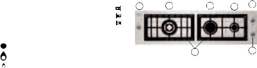
DESCRIPTION OF PRODUCT AND SYMBOLS
1. |
Removable grids |
|
|
|
|
|
|
|
|
|
|
|
2. |
4-crown burner |
|
|
|
|
|
|
|
|
|
|
|
3. |
Semi-rapid burner |
|
|
|
|
|
|
|
|
|
|
|
4. |
Auxiliary burner |
5 |
2 |
3 |
4 |
6 |
||||||
5. |
4-crown burner control knob |
|||||||||||
|
|
|
|
|
|
|
|
|
|
|||
6. |
Semi-rapid burner control knob |
|
|
|
|
|
|
|
|
|
|
|
7. |
Auxiliary burner control knob |
|
|
|
|
|
|
|
|
|
|
|
|
|
|
|
|
|
|
|
|
|
|||
Symbols
Cock closed
1 7
Max. flame Min. flame
BURNER OPERATION
1.Turn the corresponding knob anticlockwise to the max. flame symbol.
2.Press the knob against the control panel to light the burner.
3.When the burner is lit, keep the knob pressed for about 5 seconds to allow the thermocouple (provided for each burner) to heat up.
This safety device shuts off the gas if the flame goes out accidentally (draughts, interruption of gas, liquids boiling over, etc.).
The device must not be operated for more than 15 sec. If the burner does not remain lit after this time, wait at least one minute before trying to light it again.
It may happen that the burner goes out when the knob is released. This means that the thermocouple has not heated up enough.
In this case, repeat the operations described above.
18

PRACTICAL ADVICE FOR USING THE BURNERS
For maximum burner efficiency, comply with the following rules:
•Use pots and pans of suitable size for each burner (see table opposite).
•Only use flat-bottomed pots and pans.
•Use the right amount of water for cooking foods and keep the lid on.
•Do not use pots and pans that protrude over the edge of the hob
Do not use:
•Two burners at the same time with only one pot (e.g. fish kettle).
Important:
Do not place and/or drag the grids upside down on the hob as they could scratch it.
Burner |
Pot Ø |
|
|
4-crown |
from 24 to 26 cm |
semi-rapid |
from 16 to 22 cm |
auxiliary |
8 to 14 cm |
GRID POSITIONING
Position the grids and WOK pot adapter as shown in the following figures.
To avoid deterioration of the hob, it is provided with a raised grid for placing under pots wider than 26 cm.
19
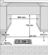
DIMENSIONS AND DISTANCES TO BE
RESPECTED (mm)
If a hood is installed above the hob, refer to the hood instructions for the correct distance.
INJECTOR TABLE
INJECTOR TABLE |
|
|
|
|
|
CATEGORY: II2H3+ |
IT + UK |
||||||||
|
|
|
|
|
|
Nominal |
|
|
|
Reduced |
Gas pressure |
||||
Type of gas |
|
Type of |
Injector |
heating |
Nominal |
heating |
|
(mbar) |
|
||||||
used |
|
|
burner |
marking |
capacity |
consumption |
capacity |
|
|
|
|
||||
|
min. |
nom. |
max. |
||||||||||||
|
|
|
|
|
|
[kW] |
|
|
|
[kW] |
|||||
|
|
|
|
|
|
|
|
|
|
|
|
|
|||
|
|
|
|
|
|
|
|
|
|
|
|
|
|
|
|
NATURAL GAS |
|
4-crown |
92 |
|
3.70 |
|
269 l/h |
1.40 |
|
|
|
|
|
||
(Methane) G20 |
|
semi-rapid |
95 |
|
1.65 |
|
157 l/h |
0.40 |
|
17 |
20 |
|
25 |
||
|
|
auxiliary |
78 |
|
1.00 |
|
95 l/h |
0.30 |
|
|
|
|
|
||
|
|
|
|
|
|
|
|
|
|
|
|
|
|
|
|
LIQUEFIED |
|
4-crown |
92 |
|
3.70 |
|
269 g/h |
1.40 |
|
|
|
|
|
||
PETROLEUM |
|
semi-rapid |
65 |
|
1.65 |
|
120 g/h |
0.40 |
|
25 |
30 |
|
35 |
||
GAS |
|
auxiliary |
50 |
|
1.00 |
|
73 g/h |
0.30 |
|
|
|||||
|
|
|
|
|
|
|
|
||||||||
(Butane) G30 |
|
|
|
|
|
|
|
|
|
|
|
|
|
|
|
|
|
|
|
|
|
|
|
|
|
|
|
|
|
|
|
LIQUEFIED |
|
4-crown |
92 |
|
3.70 |
|
269 g/h |
1.40 |
|
|
|
|
|
||
PETROLEUM |
|
semi-rapid |
65 |
|
1.65 |
|
118 g/h |
0.40 |
|
25 |
30 |
|
35 |
||
GAS |
|
auxiliary |
50 |
|
1.00 |
|
71 g/h |
0.30 |
|
|
|||||
|
|
|
|
|
|
|
|
||||||||
(Propane) G31 |
|
|
|
|
|
|
|
|
|
|
|
|
|
|
|
|
|
|
|
|
|
|
|
|
|
|
|
|
|
|
|
|
|
|
|
|
|
|
|
|
|
|
|
||||
|
|
|
Model |
|
Nominal |
|
Nominal total |
|
Air necessary (m) |
||||||
Type of gas used |
|
|
heating |
|
|
for combustion of |
|||||||||
|
configuration |
|
|
consumption |
|
||||||||||
|
|
|
|
capacity kW |
|
|
1 m3 of gas |
|
|||||||
|
|
|
|
|
|
|
|
|
|
|
|||||
|
|
|
|
|
|
|
|
|
|
|
|
|
|||
G20 20 mbar |
|
3 burners |
|
6.35 |
|
|
604 l/h |
|
|
9.52 |
|
|
|||
G30 30 mbar |
|
3 burners |
|
6.35 |
|
|
462 g/h |
|
|
30.94 |
|
|
|||
G31 30 mbar |
|
3 burners |
|
6.35 |
|
|
453 g/h |
|
|
23.80 |
|
|
|||
|
|
|
|
|
|
|
|
|
|
|
|
|
|
|
|
POWER SUPPLY: 230 V ~ 50 Hz
20
 Loading...