


Model No. WEBE37331
Serial No.
Write the serial number in the space above for future reference.
Serial Number Decal (Under Seat)
QUESTIONS?
As a manufacturer, we are committed to providing complete customer satisfaction. If you have questions, or if there are missing or damaged parts, we will guarantee complete satisfaction through direct assistance from our factory.
TO AVOID DELAYS, PLEASE CALL DIRECT TO OUR TOLLFREE CUSTOMER HOT LINE. The trained technicians on our customer hot line will provide immediate assistance, free of charge.
CUSTOMER HOT LINE:
1-800-999-3756
Mon.–Fri., 6 a.m.–6 p.m. MST
 CAUTION
Read all precautions and instructions in this manual before using this equipment. Save this manual for future reference.
USER’S MANUAL

 Visit our website at
www.weiderfitness.com
new products, prizes, fitness tips, and much more!

TABLE OF CONTENTS
WARNING DECAL PLACEMENT . . . . . . . . . . . . . . . . . . . . . . . . . . . . . . . . . . . . . . . . . . . . . . . . . . . . . . . . . . 3 IMPORTANT PRECAUTIONS . . . . . . . . . . . . . . . . . . . . . . . . . . . . . . . . . . . . . . . . . . . . . . . . . . . . . . . . . . . . . 4 BEFORE YOU BEGIN . . . . . . . . . . . . . . . . . . . . . . . . . . . . . . . . . . . . . . . . . . . . . . . . . . . . . . . . . . . . . . . . . . . 5 ASSEMBLY . . . . . . . . . . . . . . . . . . . . . . . . . . . . . . . . . . . . . . . . . . . . . . . . . . . . . . . . . . . . . . . . . . . . . . . . . . . 6 ADJUSTMENTS . . . . . . . . . . . . . . . . . . . . . . . . . . . . . . . . . . . . . . . . . . . . . . . . . . . . . . . . . . . . . . . . . . . . . . 19 CABLE DIAGRAMS . . . . . . . . . . . . . . . . . . . . . . . . . . . . . . . . . . . . . . . . . . . . . . . . . . . . . . . . . . . . . . . . . . . .23 EXERCISE GUIDELINES . . . . . . . . . . . . . . . . . . . . . . . . . . . . . . . . . . . . . . . . . . . . . . . . . . . . . . . . . . . . . . . 24 ORDERING REPLACEMENT PARTS . . . . . . . . . . . . . . . . . . . . . . . . . . . . . . . . . . . . . . . . . . . . . . . .Back Cover LIMITED WARRANTY . . . . . . . . . . . . . . . . . . . . . . . . . . . . . . . . . . . . . . . . . . . . . . . . . . . . . . . . . . . Back Cover
Note: A PART IDENTIFICATION CHART and a PART LIST/EXPLODED DRAWING is attached in the center of this manual. Remove the PART IDENTIFICATION CHART and PART LIST/EXPLODED DRAWING before beginning assembly.
WEIDER is a registered trademark of ICON Health & Fitness, Inc.
2
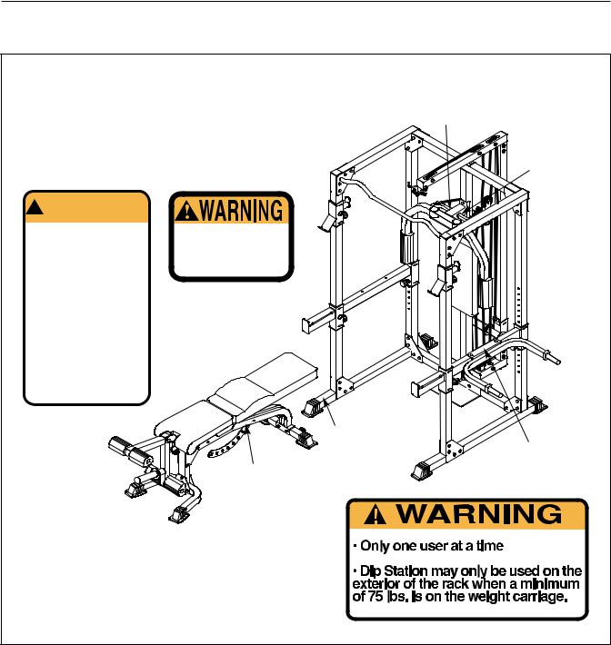
WARNING DECAL PLACEMENT
The decals shown here have been placed on the weight bench. If a decal is missing or
illegible, please call our Customer Service
Department toll-free at 1-800-999-3756, Decal 2 Monday through Friday, 6 a.m. until 6 p.m.
Mountain Time, to order a free replacement decal. Apply the decal in the location shown.
!WARNING
•Misuse of this product may result in serious injury.
•Read user’s manual and follow all warnings and operating instructions prior to use.
•Do not allow children on or around machine.
•Replace label if damaged, illegible, or removed.
Decal 1
Keep hands and fingers clear of this area.
Decal 2
 Decal 1
Decal 2
Decal 3
Decal 2
Decal 3
3

IMPORTANT PRECAUTIONS
 WARNING: To reduce the risk of serious injury, read the following important precautions before using the weight bench.
1.Read all instructions in this manual before using the weight bench. Use the weight bench only as described in this manual.
2.It is the responsibility of the owner to ensure that all users of the weight bench are adequately informed of all precautions.
3.The weight bench is intended for home use only. Do not use the weight bench in any commercial, rental, or institutional setting.
4.Use the weight bench only on a level surface. Cover the floor beneath the weight bench to protect the floor.
5.Make sure all parts are properly tightened each time the weight bench is used. Replace any worn parts immediately.
6.Keep children under 12 and pets away from the weight bench at all times.
7.Keep hands and feet away from moving parts.
8.Always wear athletic shoes for foot protection while exercising.
9.Make sure that the cables remain on the pulleys at all times. If the cables bind as you are exercising, stop immediately and make sure that the cables are on the pulleys.
10.Always set both weight rests and both safety spotters at the same height.
11.The weight bench is designed to support a maximum user weight of 300 pounds and a maximum total weight of 610 pounds. Do not place more than 310 pounds, including the barbell, on the weight rests. Do not place more than 150 pounds on the weight carriage. Note: The weight bench does not include a barbell or weights.
12.Always place an equal amount of weight on each side of the weight carriage or barbell.
13.Always secure the weights with the weight clips when they are mounted on the weight carriage.
14.Always exercise with a partner. Your partner should be ready to catch the barbell if you cannot complete a repetition.
15.Always disconnect the lat bar from the weight rack when performing an exercise that does not require the lat bar.
16.Always move the bench out of the way when performing squat exercises.
17.If you feel pain or dizziness while exercising, stop immediately and begin cooling down.
 WARNING: Before beginning this or any exercise program, consult your physician. This is especially important for persons over the age of 35 or persons with pre-existing health problems. Read all instructions before using. ICON assumes no responsibility for personal injury or property damage sustained by or through the use of this product.
4
BEFORE YOU BEGIN
Thank you for selecting the versatile WEIDER® CLUB C670 weight bench. The weight bench offers a selection of weight stations designed to develop every major muscle group of the body. Whether your goal is to tone your body, build dramatic muscle size and strength, or improve your cardiovascular system, the weight bench will help you to achieve the specific results you want.
For your benefit, read this manual carefully before using the weight bench. If you have questions after reading this manual, please call our Customer Service
Department toll-free at 1-800-999-3756, Monday through Friday, 6 a.m. until 6 p.m. Mountain Time (excluding holidays). To help us assist you, please note the product model number and serial number before calling. The model number is WEBE37331. The serial number can be found on a decal attached to the weight bench (see the front cover of this manual).
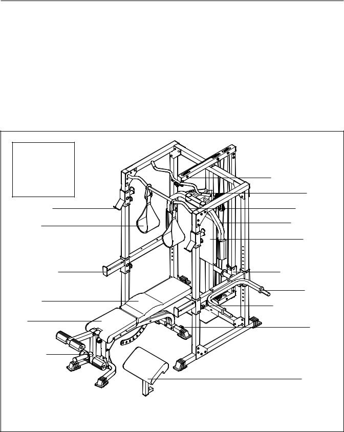
Before reading further, please review the drawing below and familiarize yourself with the parts that are labeled.
ASSEMBLED |
|
|
DIMENSIONS: |
|
|
Height: |
83 in. |
|
Width: |
66 in. |
High Pulley Station |
Depth: |
90 in. |
|
|
|
Lat Bar |
Weight Rest |
Pull-up Bar |
|
Ab Sling |
|
Butterfly Arm |
|
|
|
|
Right Side |
Backrest |
|
|
|
Safety Spotter |
Weight Carriage |
|
|
|
Dip Arm |
Backrest
Low Pulley Station
Seat
|
Wheel |
Leg Lever |
Left Side |
|
|
|
Curl Pad |
Note: The terms “right side” and “left side” are determined relative to a person sitting on the bench; they do not correspond to right and left on the drawings in this manual.
5
ASSEMBLY
Make Things Easier for Yourself
Everything in this manual is designed to ensure that the weight bench can be assembled successfully by anyone. However, it is important to realize that the versatile weight bench has many parts and that the assembly process will take time. Most people find that by setting aside plenty of time, assembly will go smoothly.
Before beginning assembly, carefully read the following information and instructions:
•Assembly requires two people.
•Place all parts in a cleared area and remove the packing materials. Do not dispose of the packing materials until assembly is completed.
•Tighten all parts as you assemble them, unless instructed to do otherwise.
•As you assemble the weight bench, make sure all parts are oriented as shown in the drawings.
•For help identifying small parts, use the PART IDENTIFICATION CHART.
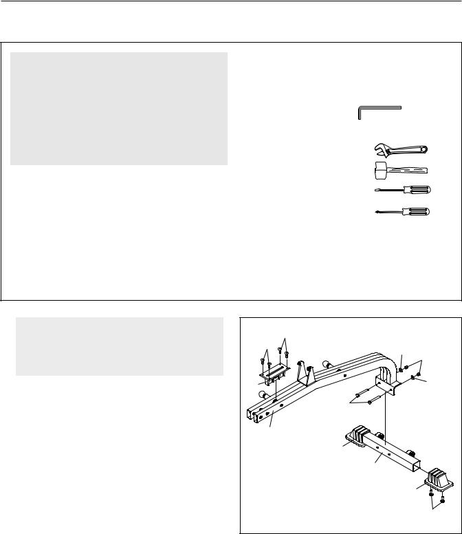
The included Allen wrench and the following tools (not included) are required for assembly:
• Two adjustable wrenches
• One rubber mallet
• One standard screwdriver
• One Phillips screwdriver
•Lubricant, such as grease or petroleum jelly, and soapy water.
Assembly will be more convenient if you have a socket set, a set of open-end or closed-end wrenches, or a set of ratchet wrenches.
1. |
1 |
|
|
|
Before beginning assembly, make sure you |
|
36 |
|
|
understand the information in the box |
|
|
|
|
|
36 |
|
|
|
above. For help identifying small parts, use |
|
35 |
|
|
|
|
34 |
||
the PART IDENTIFICATION CHART. |
|
|
|
|
|
|
|
|
|
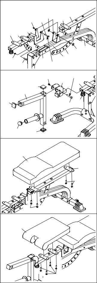
Attach a Small Base Cap (20) to the Stabilizer (2) |
93 |
|
|
35 |
|
|
|
|
|
with two M4 x 16mm Screws (36). Attach anoth- |
|
|
100 |
|
er Small Base Cap in the same manner. |
|
|
|
|
Pull the Small Adjustment Knob (23) out and slide |
|
1 |
|
|
|
|
|
|
|
the Seat Bracket Sleeve (93) between the tubes |
|
|
20 |
|
in the Bench Frame (1) as shown. Engage the |
|
|
2 |
|
Knob into the Sleeve and Bench Frame. Attach |
|
|
|
|
|
|
|
|
|
the Sleeve to the Bench Frame with four M4 x |
|
|
|
|
16mm Screws (36). |
|
|
20 |
|
Attach the Bench Frame (1) to the Stabilizer (2) |
|
|
|
36 |
with two M10 x 65mm Bolts (100), two M10 |
|
|
|
|
Washers (35), and two M10 Nylon Locknuts (34). |
|
|
|
|
Do not tighten the Locknuts yet. |
|
|
|
|
6
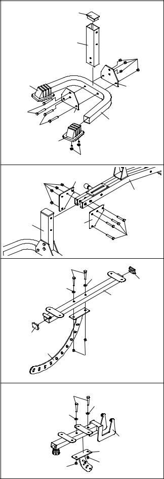
2. Attach a Small Base Cap (20) to the Bench Base |
2 |
|
|
|
(3) with two M4 x 16mm Screws (36). Attach the |
|
14 |
|
|
|
|
|
||
other Small Base Cap in the same manner. |
|
|
|
|
Press the 51mm x 76mm Inner Cap (14) into the |
|
|
4 |
|
indicated end of the Bench Leg (4). |
|
|
|
|
Attach the Bench Leg (4) to the Bench Base (3) |
|
|
|
34 |
|
|
|
|
|
with four M10 x 71mm Bolts (31), two Bench |
|
|
|
|
Base Joint Plates (25), and four M10 Nylon |
20 |
|
|
|
Locknuts (34). Do not tighten the Locknuts yet. |
|
|
25 |
|
|
|
|
|
|
|
31 |
|
25 |
|
|
|
|
3 |
|
|
|
31 |
|
|
|
|
|
|
|
|
|
|
20 |
|
|
|
|
36 |
|
3. Attach the Bench Leg (4) to the Bench Frame (1) |
3 |
|
|
|
with four M10 x 94mm Bolts (98), two Bench Joint |
|
24 |
|
|
|
34 |
|
||
Plates (24), and four M10 Nylon Locknuts (34). |
|
|
|
|
|
|
|
|
|
Tighten the M10 Nylon Locknuts (34) used in |
|
|
|
1 |
|
|
|
|
|
steps 1–3. |
|
|
|
|
|
4 |
|
24 |
|
|
|
|
|
98 |
4. Press two 38mm x 50mm Inner Caps (15) into |
4 |
|
30 |
|
the Backrest Frame (6). |
|
|
||
|
|
|
||
|
|
|
35 |
|
|
|
|
|
|
Attach the Backrest Bracket (16) to the Backrest |
|
|
35 |
15 |
|
|
|
||
Frame (6) with two M10 x 56mm Bolts (30), two |
|
|
|
6 |
M10 Washers (35), and two M10 Nylon Locknuts |
|
|
|
|
|
|
|
|
|
(34). |
|
|
|
|
|
15 |
|
|
|
|
|
16 |
|
|
|
|
|
34 |
|
5. Attach the Seat Bracket (17) to the Seat Frame |
5 |
|
|
|
(7) with two M10 x 56mm Bolts (30), two M10 |
|
30 |
|
|
|
|
|
||
Washers (35), and two M10 Nylon Locknuts (34). |
|
|
|
35 |
Do not tighten the Locknuts yet. |
|
|
35 |
|
|
|
|
|
|
|
|
|
|
7 |
|
|
|
|
17 |
|
|
|
34 |
34 |
|
|
|
|
7
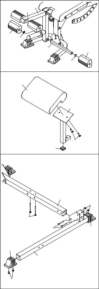
6. Pull out the Small Adjustment Knob (23) that is |
6 |
|
|
|
|
|
|
|
nearer the Stabilizer (2). Insert the Backrest |
|
|
|
|
|
|
|
|
|
|
|
|
|
|
|
|
|
Bracket (16) between the tubes on the Bench |
|
|
|
|
|
|
6 |
|
Frame (1) and engage the Small Adjustment Knob |
|
|
|
|
35 |
23 |
|
|
|
|
34 |
99 |
|
|
|||
into one of the holes in the Bracket. |
|
|
|
|
|
|||
|
|
|
|
|
|
|||
Pull out the Small Adjustment Knob (23) by the |
7 |
17 |
23 |
|
|
|
|
|
Seat Bracket Sleeve (93). Insert the Seat Bracket |
|
|
|
|
|
|
||
(17) into the Seat Bracket Sleeve and engage the |
|
|
|
|
|
|
|
|
Small Adjustment Knob into one of the holes in the |
|
|
|
|
|
|
|
2 |
Bracket. |
|
|
|
|
|
|
35 |
|
|
|
|
|
|
|
|
||
Lubricate the M10 x 102mm Bolt (99) with grease. |
34 |
|
|
93 |
|
1 |
16 |
|
102 |
Lubricate |
|
|
|||||
Attach the Seat Frame (7) and the Backrest Frame |
|
|
|
|
||||
(6) to the Bench Frame (1) with the Bolt, two M10 |
|
|
|
|
|
|
|
|
Washers (35), and an M10 Nylon Locknut (34). Do |
7 |
|
|
|
34 |
|
Lubricate |
|
not overtighten the Locknut; the Seat and |
|
|
|
|
18 |
|
||
|
|
|
|
|
7 |
|
||
Backrest Frames must be able to pivot easily. |
|
|
|
|
|
|
||
|
|
13 |
|
|
|
|
||
|
|
|
|
|
|
|
|
|
Attach an M10 x 19mm Bolt (102) to the round |
|
|
5 |
|
|
|
|
|
hole in the Seat Bracket (17) with an M10 Nylon |
13 |
|
|
|
|
|
22 |
|
Locknut (34). |
|
|
|
|
|
|
||
|
|
|
|
|
103 |
|
||
|
|
|
|
|
|
|
||
Tighten the M10 Nylon Locknuts (34) used in |
|
|
|
|
|
|
|
|
step 5. |
|
|
|
|
|
|
|
|
7. Press three 50mm Square Inner Caps (13) and a |
|
19 |
|
|
|
|
|
|
48mm Round Inner Cap (19) into the Leg Lever |
|
13 |
|
|
|
|
|
|
(5). |
|
|
|
|
|
|
|
|
Lubricate the M10 x 85mm Bolt (103) with |
8 |
|
|
|
|
|
|
|
|
|
|
|
|
|
|
|
|
grease. Attach the Leg Lever (5) to the Leg Lever |
|
11 |
|
|
|
|
|
|
Bracket (18) with the Bolt and an M10 Nylon |
|
|
|
|
|
|
|
|
Locknut (34). |
|
|
|
|
|
|
|
|
Loosen the Adjustment Knob (22) by turning it |
|
|
|
|
|
|
6 |
|
|
|
|
|
|
|
|
|
|
counterclockwise several turns. Pull the Knob out |
|
|
|
|
|
|
|
|
and slide the Leg Lever Bracket (18) into the Seat |
|
|
|
|
|
|
29 |
|
Frame (7). Tighten the Adjustment Knob into the |
|
|
|
|
|
|
|
|
Leg Lever Bracket. |
|
|
|
|
|
|
|
|
8. Attach the Backrest (11) to the Backrest Frame |
|
|
|
|
|
|
|
|
(6) with four M6 x 16mm Screws (29) |
|
|
|
|
|
|
|
|
|
|
|
29 |
|
|
|
|
|
9. Attach the Seat (10) to the Seat Frame (7) with |
9 |
|
|
|
|
|
|
|
four M6 x 16mm Screws (29) |
|
|
|
|
|
|
|
|
|
|
|
|
|
|
|
|
|
|
|
10 |
|
|
|
|
|
|
|
|
|
|
|
|
29 |
|
|
8
10.Press two 25mm Square Inner Caps (28) into a Pad Tube (27). Slide the Pad Tube into a hole in the Leg Lever (5). Slide two Foam Pads (26) onto the Pad Tube.
Assemble the other Pad Tube (27) in the same manner.
11.Press a 45mm Square Inner Cap (12) into the bottom of the Curl Post (8).
Attach the Curl Pad (9) to the Curl Post (8) with two M6 x 16mm Screws (29).
12.Attach a Large Base Cap (70) to the Left Base (40) with two M4 x 16mm Screws (36). Attach another Large Base Cap to the other end of the Left Base in the same manner.
Attach the Left Base (40) to the Center Base (39) with two M10 x 78mm Bolts (32) and two M10 Nylon Locknuts (34). Do not tighten the
Locknuts yet.
Repeat this step with the Right Base (not shown).
Insert two M10 x 75m Carriage Bolts (90) up through the Center Base (39).
10 |
5 |
|
|
27 |
|
26 |
28 |
|
|
|
|
|
27 |
26 |
|
|
28 |
11 |
|
|
|
9 |
|
|
|
8 |
|
|
29 |
|
12 |
|
12 |
|
|
|
|
39 |
|
|
34 |
|
90 |
|
|
32 |
70 |
70 |
|
|
|
40 |
|
36 |
|
|
9
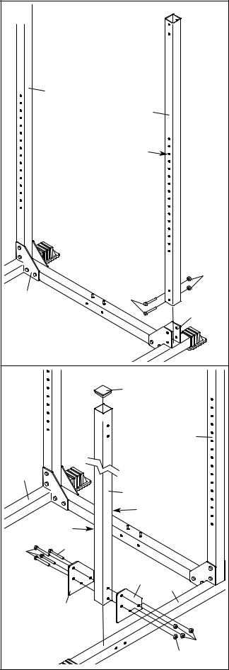
13. Attach a Rear Upright (43) to the Left Base (40) |
13 |
|
with two M10 x 78mm Bolts (32) and two M10 |
|
|
|
|
|
Nylon Locknuts (34). Note: The Rear Uprights |
|
|
are shorter than the Front Uprights (not |
|
|
shown). Make sure the holes are on the side |
|
|
shown. Do not tighten the Locknuts yet. |
|
|
Repeat this step with the other Rear Upright |
|
43 |
(43) and the Right Base (38). |
|
|
|
|
|
|
|
43 |
|
|
Holes |
|
|
34 |
|
38 |
32 |
|
|
40 |
14. Press a 60mm Square Inner Cap (64) into the top |
14 |
|
of the Left Front Upright (44). |
|
|
|
64 |
|
|
|
|
Attach the Left Front Upright (44) to the Left Base |
|
|
(40) with four M10 x 78mm Bolts (32), two Rack |
|
|
Joint Plates (85), and two M10 Nylon Locknuts |
|
43 |
(34). Do not tighten the Locknuts yet. |
|
|
Make sure the holes on the Left Front Upright |
|
|
(44) face the holes on the Rear Upright (43), |
38 |
|
and that the numbers on the Left Front |
|
|
|
44 |
|
Upright face the numbers on the Right Front |
|
|
Upright (not shown). |
|
Holes |
|
|
|
Repeat this step with the right Front Upright |
|
Numbers |
(not shown) and the Right Base (38). |
32 |
32 |
|
||
|
|
|
|
|
85 |
|
|
40 |
|
|
85 |
|
|
34 |
|
|
34 |
10
15.Loosen the two Adjustment Knobs (22) on the Left Safety Spotter (51) by turning them counterclockwise. Pull both Knobs out at the same time and slide the Left Safety Spotter (51) onto the Left Uprights (43, 44) and engage and tighten the Adjustment Knobs (22) into a set of holes in the Uprights.
Repeat this step with the Right Safety Spotter (50) and Right Uprights (not shown).
16.Loosen the Adjustment Knob (22) on the Right Weight Rest (52) by turning it counterclockwise. Pull the Knob out and slide the Right Weight Rest (52) onto the Right Front Upright (110). Engage and tighten the Adjustment Knob (22) into a hole in the Upright.
Repeat this step with the Left Weight Rest (not shown) and the Left Front Upright (not shown).
17.Press a 60mm Square Inner Cap (64) into the indicated end of the Right Top Frame (47).
Attach the Right Top Frame (47) to the right Rear Upright (43) with two M10 x 78mm Bolts (32) and two M10 Nylon Locknuts (34). Do not tighten the
Locknuts yet.
Repeat this step with the Left Top Frame (not shown) and the left Rear Upright (not shown).
15 |
|
|
51 |
|
22 |
|
22 |
|
43 |
50 |
44 |
16 |
|
52 |
|
|
22 |
|
110 |
17 |
64 |
|
|
|
34 |
|
47 |
|
32 |
|
43 |
11
 Loading...