


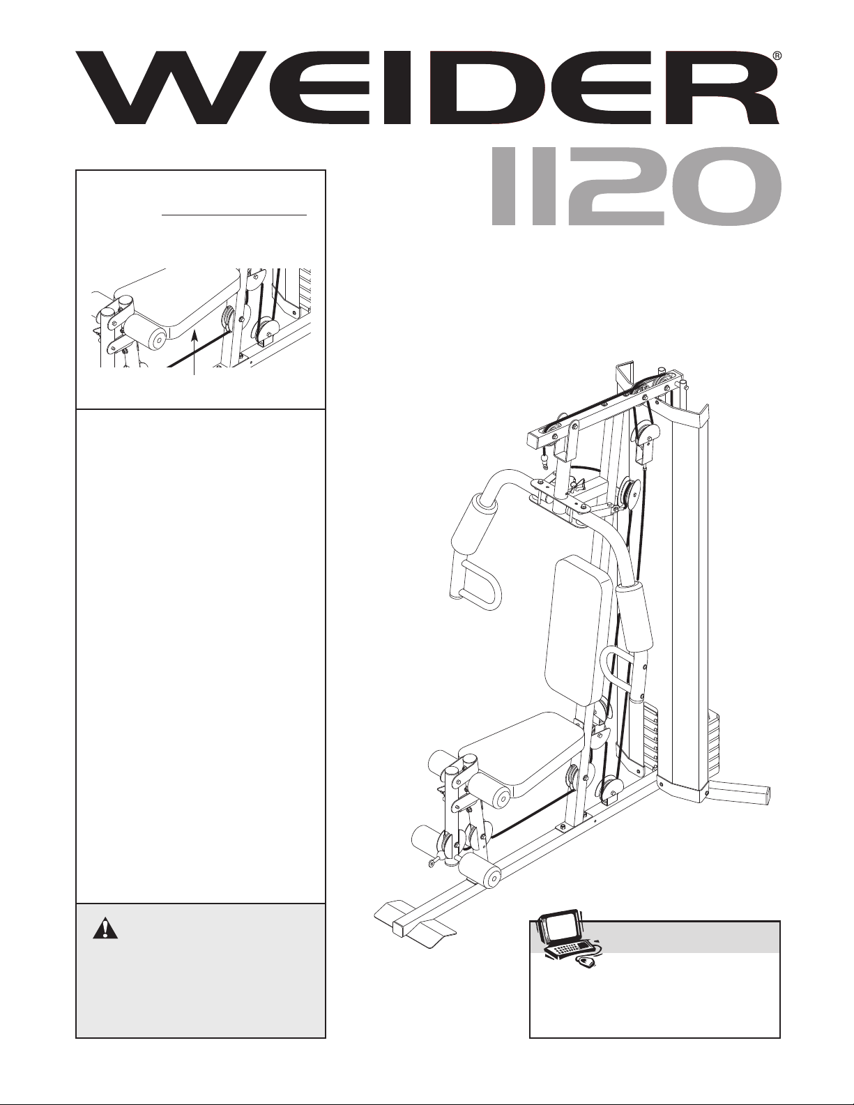
1120
CAUTION
Read all precautions and instruc
-
tions in this manual before using
this equipment. Save this manual
for future reference.
Model No. WESY19540
Serial No.
Write the serial number in the
space above for future reference.
Serial Number Decal (Under Seat)
QUESTIONS?
As a manufacturer, we are com-
mitted to providing complete
customer satisfaction. If you
have questions, or if there are
missing or damaged parts, we
will guarantee complete satis-
faction through direct assis-
tance from our factory.
TO AVOID DELAYS, PLEASE
CALL DIRECT TO OUR TOLL-
FREE CUSTOMER HOT LINE.
The trained technicians on our
customer hot line will provide
immediate assistance, free of
charge.
CUSTOMER HOT LINE:
1-877-992-5999
Mon.–Fri., 6 a.m.–6 p.m. MST
USER’S MANUAL
Visit our website at
www.weiderfitness.com
new products, prizes,
fitness tips, and much more!
Patent Pending
2
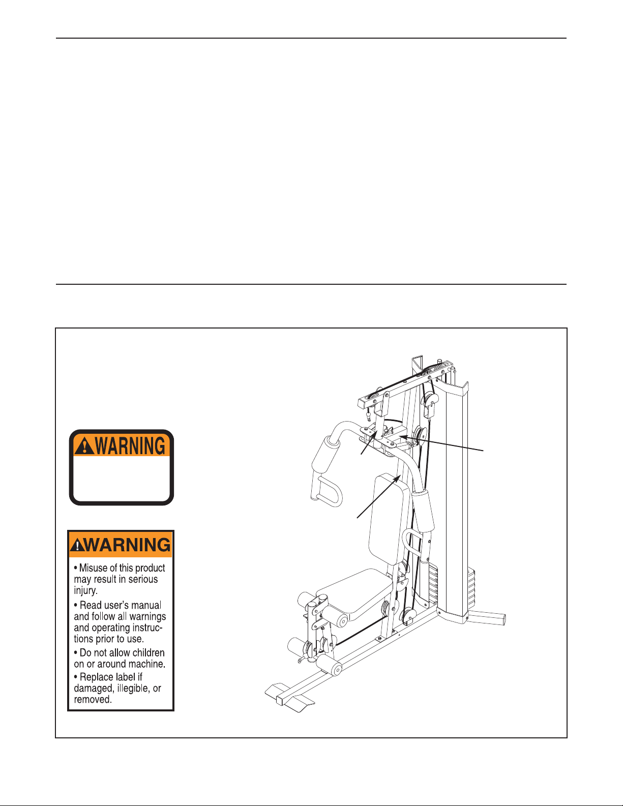
WARNING DECAL PLACEMENT
WARNING DECAL PLACEMENT . . . . . . . . . . . . . . . . . . . . . . . . . . . . . . . . . . . . . . . . . . . . . . . . . . . . . . . . . . . . . 2
IMPOR
TANT PRECAUTIONS . . . . . . . . . . . . . . . . . . . . . . . . . . . . . . . . . . . . . . . . . . . . . . . . . . . . . . . . . . . . . . . . 3
BEFORE YOU BEGIN . . . . . . . . . . . . . . . . . . . . . . . . . . . . . . . . . . . . . . . . . . . . . . . . . . . . . . . . . . . . . . . . . . . . . . 4
ASSEMBLY . . . . . . . . . . . . . . . . . . . . . . . . . . . . . . . . . . . . . . . . . . . . . . . . . . . . . . . . . . . . . . . . . . . . . . . . . . . . . . 5
ADJUSTMENTS . . . . . . . . . . . . . . . . . . . . . . . . . . . . . . . . . . . . . . . . . . . . . . . . . . . . . . . . . . . . . . . . . . . . . . . . . . 17
WEIGHT RESISTANCE CHART . . . . . . . . . . . . . . . . . . . . . . . . . . . . . . . . . . . . . . . . . . . . . . . . . . . . . . . . . . . . . .19
CABLE DIAGRAMS . . . . . . . . . . . . . . . . . . . . . . . . . . . . . . . . . . . . . . . . . . . . . . . . . . . . . . . . . . . . . . . . . . . . . . .20
MAINTENANCE . . . . . . . . . . . . . . . . . . . . . . . . . . . . . . . . . . . . . . . . . . . . . . . . . . . . . . . . . . . . . . . . . . . . . . . . . .21
EXERCISE GUIDELINES . . . . . . . . . . . . . . . . . . . . . . . . . . . . . . . . . . . . . . . . . . . . . . . . . . . . . . . . . . . . . . . . . . 22
ORDERING REPLACEMENT PARTS . . . . . . . . . . . . . . . . . . . . . . . . . . . . . . . . . . . . . . . . . . . . . . . . . .Back Cover
LIMITED WARRANTY . . . . . . . . . . . . . . . . . . . . . . . . . . . . . . . . . . . . . . . . . . . . . . . . . . . . . . . . . . . . . . Back Cover
Note: A PART IDENTIFICATION CHART and a PART LIST/EXPLODED DRAWING are attached in the center of
this manual. Remove the PART IDENTIFICATION CHART and PART LIST/EXPLODED DRAWING before begin-
ning assembly.
WEIDER is a registered trademark of ICON IP
, Inc.
TABLE OF CONTENTS
The decals shown here have been placed on
the weight system. If a decal is missing or illegi-
ble, please call our Customer Service
Department toll-free at 1-877-992-5999, Monday
through Friday, 6 a.m. until 6 p.m. Mountain
Time, to order a free replacement decal. Apply
the decal in the location shown.
Decal 1
Keep hands and
fingers clear of
this area.
Decal 2
Decal 1
Decal 1—This
decal is placed
on both sides
of the upright
Decal 2

1. Read all instructions in this manual before
using the weight system. Use the weight sys-
tem only as described in this manual.
2. It is the responsibility of the owner to ensure
that all users of the weight system are ade-
quately informed of all precautions.
3. The weight system is intended for home use
only. Do not use the weight system in any
commercial, rental, or institutional setting.
4. Use the weight system only on a level sur-
face. Cover the floor beneath the weight sys-
tem to protect the floor.
5. Make sure all parts are properly tightened
each time the weight system is used.
Replace any worn parts immediately.
6. Keep children under 12 and pets away from
the weight system at all times.
7. Always wear athletic shoes for foot protec-
tion while exercising.
8. Keep hands and feet away from moving parts.
9. The weight system is designed to support a
maximum user weight of 300 pounds.
10. Always secure the weight stack with the lock
pin and lock after exercising to prevent
unauthorized use of the weight system (see
LOCKING THE WEIGHT STACK on page 18).
11. Make sure that the cables remain on the pul-
leys at all times. If the cables bind as you are
exercising, stop immediately and make sure
that the cables are on the pulleys.
12. Always stand on the foot plate when per-
forming an exercise that could cause the
weight system to tip.
13. Never release the arms, leg lever, lat bar, or
handle strap while weights are raised. The
weights will fall with great force.
14.
Always disconnect the lat bar from the
weight system when performing an exercise
that does not use the lat bar.
15. If you feel pain or dizziness while exercising,
stop immediately and begin cooling down.
WARNING: Before beginning this or any exercise program, consult your physician. This
is especially important for persons over the age of 35 or persons with pre-existing health problems.
Read all instructions before using. ICON assumes no responsibility for personal injury or property
damage sustained by or through the use of this product.
WARNING: To reduce the risk of serious injury, read the following important precautions
before using the weight system.
IMPORTANT PRECAUTIONS
3
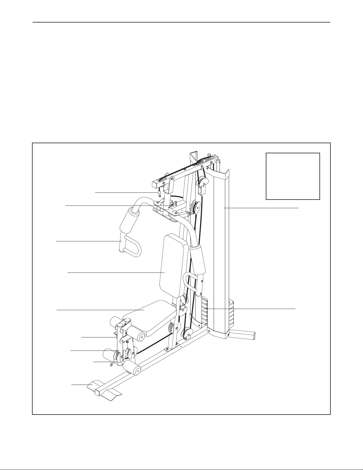
ASSEMBLED
DIMENSIONS:
Height: 90 in.
Width: 87 in.
Depth: 77 in.
4
Shroud
High Pulley Station
Low Pulley Station
Right Side
Left Side
Note: The terms “right side” and “left side” are determined
relative to a person sitting on the seat; they do not corre-
spond to right and left on the drawings in the manual.
Backrest
Weights
Leg Lever
Foot Plate
Seat
Arm
Arm Pin
Leg Lever Pin
BEFORE YOU BEGIN
Thank you for selecting the versatile WEIDER
®
1120
weight system. The weight system offers a selection of
weight stations designed to develop every major mus-
cle group of the body. Whether your goal is to tone
your body
, build dramatic muscle size and strength, or
improve your cardiovascular system, the weight sys-
tem will help you to achieve the specific results you
want.
For your benefit, read this manual carefully before
using the weight system. If you have questions after
reading this manual, please call our Customer Service
Department toll-free at 1-877-992-5999, Monday
through Friday, 6 a.m. until 6 p.m. Mountain Time
(excluding holidays). To help us assist you, please
note the product model number and serial number
before calling.
The model number is WESY19540. The
serial number can be found on a decal attached to the
weight system (see the front cover of this manual).
Before reading further, please review the drawing
below and familiarize yourself with the parts that are
labeled.
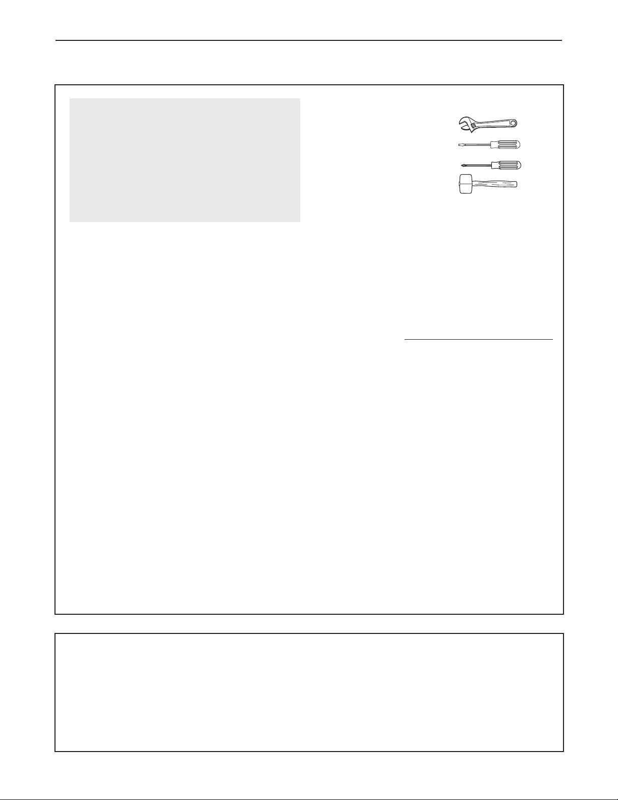
Make sure you have the following tools:
• Two adjustable wrenches
• One standard screwdriver
• One phillips screwdriver
• One rubber mallet
• You will also need grease or petroleum jelly, a
small amount of soapy water, and clear tape or
masking tape.
Note: Assembly will be more convenient if you have
a socket set, a set of open-end or closed-end
wrenches, or a set of ratchet wrenches.
How to Identify Parts
To help you identify the small parts used in assembly,
we have included a P
ART IDENTIFICATION CHART
in the center of this manual. Place the chart on the
floor and use it to easily identify parts during each
assembly step. Note: Some small parts may have
been pre-attached. If a part is not in the parts
bag, check to see if it has been pre-attached.
How to Orient Parts
As you assemble the weight system, make sure that
all parts are oriented exactly as shown in the draw-
ings.
Tightening Parts
Tighten all parts as you assemble them, unless
instructed to do otherwise.
Questions?
If you have questions after reading the assembly
instructions, please call our Customer Service
Department at 1-877-992-5999.
5
Assembly Requires Two Persons
For your convenience and safety, assemble the
weight system with the help of another person.
Set Aside Enough Time
Due to the many features of the weight system, the
assembly process will require several hours. By
setting aside plenty of time and by deciding to
make the task enjoyable, assembly will go smoothly.
You may want to assemble the weight system over
a couple of evenings.
Select a Location for the Weight System
Because of its weight and size, the weight system
should be assembled in the location where it will be
used. Make sure that there is enough room to walk
around the weight system as you assemble it.
How to Unpack the Box
To make assembly as easy as possible, we have
divided the assembly process into four stages.
The
parts needed for each stage are found in individual
bags.
Important: Wait until you begin each stage
to open the parts bag for that stage. Place all
parts of the weight system in a cleared area and
remove the packing materials. Do not dispose
of
the packing materials until assembly is completed.
Make Assembly Easier for Yourself
Everything in this manual is designed to
ensure that the weight system can be assem-
bled successfully by anyone. Before begin-
ning assembly, make sure to read the
information on this page. This brief intro-
duction will save you much more time than
it takes to read it.
The Four Stages of the Assembly Process
Frame Assembly—You will begin by assembling
the base and the uprights that form the skeleton of
the weight system.
Arm Assembly—During this stage you will
assemble the arms and the leg lever.
Cable Assembly—During this stage you will
attach the cables and pulleys that connect the
arms to the weights.
Seat Assembly—During the final stage you will
assemble the seats and the backrests.
ASSEMBLY
6
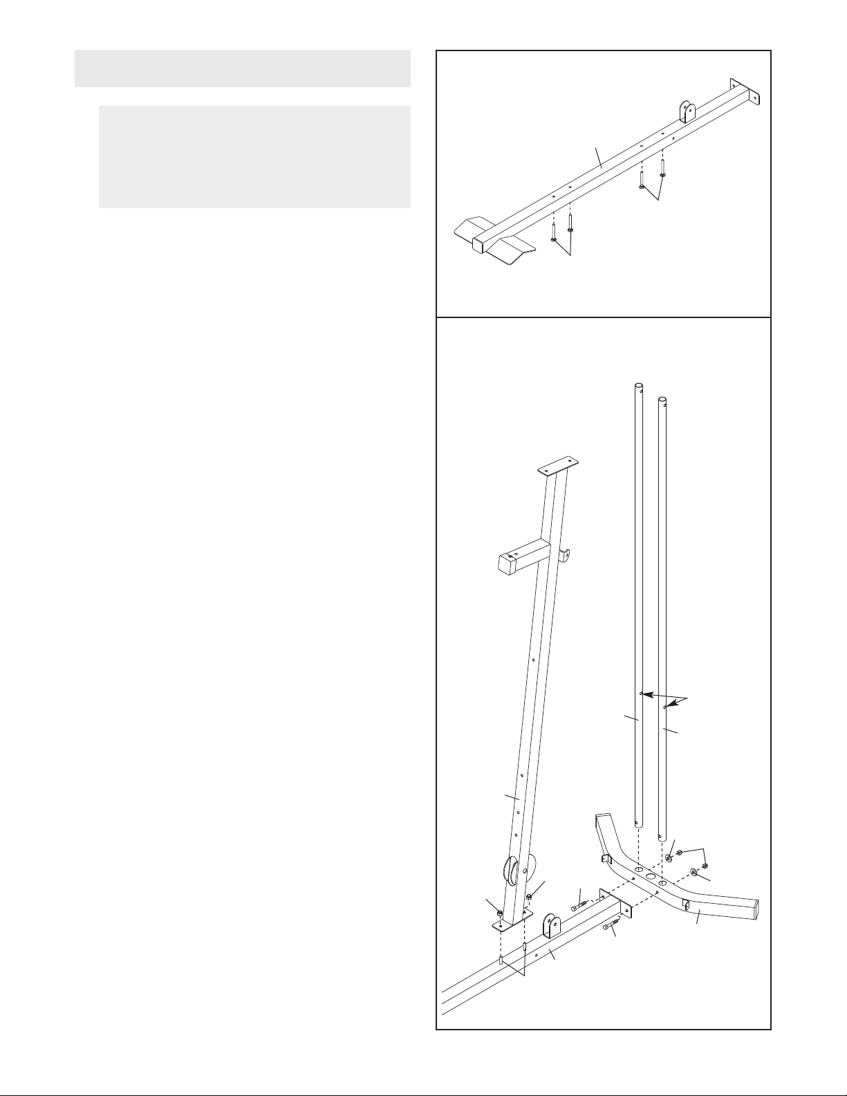
2. Attach the Base (1) and the two Weight Guides
(21) to the Stabilizer (2) with two M10 x 67mm
Bolts (71), two M10 Washers (57), and two M10
Nylon Locknuts (56). Make sure the indicated
holes in the Weight Guides are nearer the bot-
tom.
Attach the Upright (3) to the Base (1) with the two
M10 x 65mm Carriage Bolts (78) and two M10
Nylon Locknuts (56). Do not tighten the
Locknuts yet.
1.
Insert two M10 x 65mm Carriage Bolts (78) and
two M8 x 63mm Carriage Bolts (87) up through
the Base (1). Note: It may be helpful to place a
piece of tape over the bolt heads to hold them
in place.
Before beginning assembly, make sure you
understand the information in the box on
page 5. Refer to the PART IDENTIFICATION
CHART in the center of this manual for help
identifying small parts.
Frame Assembly
1
1
78
87
2
78
56
56
3
1
56
71
71
2
57
57
21
Holes
21
7
3. Attach the Front Leg (7) to the Base (1) with the
two M8 x 63mm Carriage Bolts (87) and two M8
Nylon Locknuts (58).
Do not tighten the
Locknut yet.
Attach the Leg Bumper (60) to the Front Leg (7)
with an M4 x 20mm Self-tapping Screw (69) and
an M4 Washer (33). Make sure the end of the
Bumper is pointing up.
4. Attach the Seat Frame (6) to the Upright (3) with
two M8 x 65mm Bolts (68), two M8 Washers (59),
and two M8 Nylon Locknuts (58).
Do not tighten
the Locknuts yet.
Attach the Seat Frame (6) to the Front Leg (7)
in the same manner.
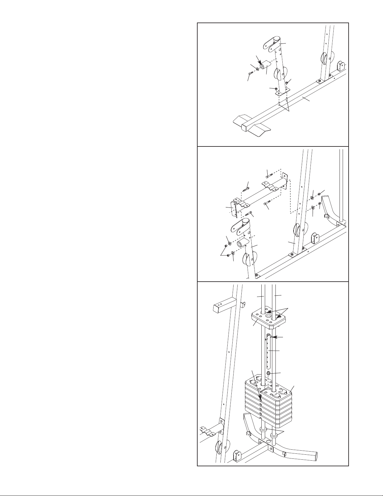
5. Slide the two Weight Bumpers (27) onto the
Weight Guides (21). Slide the six Weights (22)
onto the Weight Guides, with the pin holes on the
bottom as shown.
Insert the Weight Tube Bumper (23) into the
Weight Tube (24). Insert the Weight Tube into the
weight stack. Make sure the pin on the W
eight
T
ube is oriented as shown.
Lubricate the indicated holes in the Top Weight
(25) with the included grease packet. Slide the
Top Weight onto the Weight Guides (21).
3
4
87
58
58
69
33
Up
60
7
1
6
68
68
68
59
59
59
59
3
7
58
58
58
68
5
25
21
21
22
27
23
24
Pin
Pin
Hole
Grease
8
6. Attach the Top Frame (4) to the Upright (3) with
two M10 x 67mm Bolts (71), two M10 Washers
(57), and two M10 Nylon Locknuts (56).
Do not
tighten the Locknuts yet.
Attach the Top Frame (4) between the Weight
Guides (21) with an M10 x 155mm Bolt (74), two
M10 Washers (57), two 19mm Spacers (76), and
an M10 Nylon Locknut (56). Do not tighten the
Locknuts yet.
7. Attach the Left Cap (19) and the Right Cap (20)
to the bottom of the Shroud (17) with two M5 x
20mm Self-tapping Screws (64) and two M5
Washers (72).
Attach the Top Cap (18) to the top of the Shroud
(17) with two M6 x 16mm Screws (62), four M6
Washers (82), and two M6 Locknuts (92).
6
7
4
3
56
56
74
21
21
57
57
57
57
76
76
71
56
18
62
62
82
92
82
17
20
19
64
72
72
9
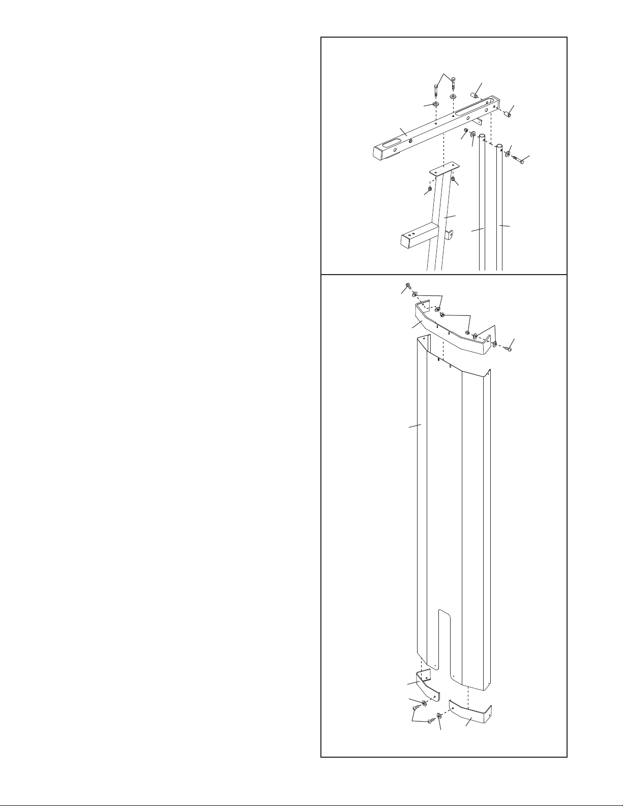
8. Attach the Shroud (17) to the Top Frame (4) with
two M6 x 16mm Screws (62) and two M6
W
ashers (82).
Attach the Shroud (17) to the brackets on the
Stabilizer (2) with two M6 x 16mm Screws (62)
and two M6 Washers (82).
Make sure the brack-
ets are inside the Shroud.
Tighten the Nylon Locknuts (56, 58) used in
steps 2–7.
9. Grease the M10 x 77mm Bolt (79). Orient the Leg
Lever (8) as shown. Attach the Leg Lever to the
Front Leg (7) with the Bolt and an M10 Nylon
Locknut (56). Do not overtighten the Locknut;
the Leg Lever must be able to pivot easily.
10.
Grease the M10 x 80mm Bolt (80). Attach the
Pivot Frame (5) to the
T
op Frame (4) with the Bolt
and an M10 Nylon Locknut (56).
Do not over-
tighten the Locknut; the Pivot Frame must be
able to pivot easily
.
Attach the two Arm Pins (40) to the Pivot Frame
(5) with two M4 x 20mm Self-tapping Screws
(69). Insert the
Arm Pins into the two holes in the
Upright (3).
8
9
10
62
82
17
4
62
62
82
82
Bracket
2
56
79
Grease
Welded
Support
7
8
Grease
Holes
5
56
80
69
69
3
40
40
4
Arm Assembly
 Loading...