


 Loading...
Dual-Channel
Arbitrary Waveform Generator
User Manual
FG-30802T
FG-31602T
FG-32502T
General Warranty
We warrant that the product will be free from defects in materials and workmanship for a period of 3 years from the date of purchase of the product by the original purchaser from our company. The warranty period for accessories such as probes, battery is 12 months. This warranty only applies to the original purchaser and is not transferable to a third party.
If the product proves defective during the warranty period, we will either repair the defective product without charge for parts and labour, or will provide a replacement in exchange for the defective product. Parts, modules and replacement products used by our company for warranty work may be new or reconditioned like new. All replaced parts, modules and products become the property of our company.
In order to obtain service under this warranty, the customer must notify our company of the defect before the expiration of the warranty period. Customer shall be responsible for packaging and shipping the defective product to the designated service centre, a copy of the customers proof of purchase is also required.
This warranty shall not apply to any defect, failure or damage caused by improper use or improper or inadequate maintenance and care. We shall not be obligated to furnish service under this warranty a) to repair damage resulting from attempts by personnel other than our company representatives to install, repair or service the product; b) to repair damage resulting from improper use or connection to incompatible equipment; c) to repair any damage or malfunction caused by the use of not our supplies; or d) to service a product that has been modified or integrated with other products when the effect of such modification or integration increases the time or difficulty of servicing the product.
Please contact the nearest Sales and Service Offices for services.
Excepting the after-sales services provided in this summary or the applicable warranty statements, we will not offer any guarantee for maintenance definitely declared or hinted, including but not limited to the implied guarantee for marketability and special-purpose acceptability. We should not take any responsibilities for any indirect, special or consequent damages.
Table of Contents |
|
1. General Safety Requirement ................................................................ |
1 |
2. Safety Terms and Symbols.................................................................... |
2 |
3. Quick start............................................................................................ |
3 |
Front panel .................................................................................................................................. |
3 |
Rear Panel ................................................................................................................................... |
5 |
Power On..................................................................................................................................... |
6 |
User Interface.............................................................................................................................. |
7 |
Use Build-in Help......................................................................................................................... |
8 |
4. Panel Operation ................................................................................... |
9 |
Channel Setting ........................................................................................................................... |
9 |
Select the channel for configuration .................................................................................. |
9 |
Turn On/Off Channel Output .............................................................................................. |
9 |
Channel Copy ...................................................................................................................... |
9 |
Waveform Setting........................................................................................................................ |
9 |
Output Sine Wave ............................................................................................................. |
10 |
Set the frequency/period ......................................................................................... |
10 |
Set the amplitude ..................................................................................................... |
11 |
Set the offset............................................................................................................. |
11 |
Set the high level....................................................................................................... |
11 |
Set the low level........................................................................................................ |
11 |
Set the start phase.................................................................................................... |
12 |
Output Square Wave......................................................................................................... |
12 |
Output Ramp Wave........................................................................................................... |
13 |
Set the symmetry...................................................................................................... |
13 |
Output Pulse Wave ........................................................................................................... |
14 |
Set the pulse width/duty cycle ................................................................................. |
17 |
Set the rising/falling time ......................................................................................... |
18 |
Output Noise Wave........................................................................................................... |
18 |
Output Arbitrary Wave ..................................................................................................... |
19 |
Choose build-in waves .............................................................................................. |
20 |
Output Harmonic Wave .................................................................................................... |
25 |
Harmonic wave function overview........................................................................... |
25 |
Select the harmonic type.......................................................................................... |
25 |
Set the harmonic times............................................................................................. |
26 |
Set the harmonic number......................................................................................... |
26 |
Set the harmonic amplitude..................................................................................... |
26 |
Set the harmonic phase............................................................................................ |
26 |
Output the modulated waves................................................................................................... |
27 |
Amplitude Modulation(AM) ............................................................................................. |
27 |
i
Frequency Modulation (FM)............................................................................................. |
29 |
Phase Modulation (PM) .................................................................................................... |
31 |
Pulse Width Modulation (PWM) ...................................................................................... |
32 |
Amplitude shift keying (ASK) ............................................................................................ |
33 |
Phase Shift Keying (PSK).................................................................................................... |
35 |
Frequency Shift Keying (FSK) ............................................................................................ |
37 |
Hexadecimal frequency shift keying (3FSK).............................................................................. |
38 |
Quaternary frequency shift keying (4FSK)................................................................................ |
39 |
Binary phase shift keying (BPSK)............................................................................................... |
40 |
Oscillating keying (OSK)............................................................................................................. |
41 |
Output the sweep frequency (Sweep)...................................................................................... |
43 |
Output the burst (Burst) ........................................................................................................... |
44 |
Set N cycle burst ............................................................................................................... |
45 |
Set the gated burst ........................................................................................................... |
46 |
Counter...................................................................................................................................... |
47 |
Utility function setting .............................................................................................................. |
48 |
Display Setting................................................................................................................... |
48 |
Brightness Control..................................................................................................... |
48 |
Screen Saver.............................................................................................................. |
49 |
Separator................................................................................................................... |
49 |
Date........................................................................................................................... |
49 |
CH1/2 Settings................................................................................................................... |
49 |
Synchronize ............................................................................................................... |
49 |
Output Setting................................................................................................................... |
50 |
Set the load ............................................................................................................... |
50 |
Interface Setting................................................................................................................ |
51 |
System Setting................................................................................................................... |
52 |
Select the language................................................................................................... |
52 |
Buzzer........................................................................................................................ |
52 |
Clock source .............................................................................................................. |
52 |
Clock Output ............................................................................................................. |
53 |
Firmware update....................................................................................................... |
53 |
Restore to factory setting ......................................................................................... |
53 |
Edit the Arbitrary Wave (Edit) .................................................................................................. |
57 |
File system (Store)..................................................................................................................... |
58 |
Save Current Arbitrary Wave ............................................................................................ |
59 |
Bring up arbitrary wave files in internal/external memory.............................................. |
59 |
Clear waveform from memory ......................................................................................... |
60 |
Save/recall instrument settings (Preset) .................................................................................. |
60 |
Use build-in help (Help) ............................................................................................................ |
61 |
5. Communicate with PC........................................................................ |
62 |
Using USB Port .......................................................................................................................... |
62 |
Using LAN Port .......................................................................................................................... |
62 |
ii
|
Connect Directly................................................................................................................ |
62 |
|
Connect through a Router ................................................................................................ |
63 |
6. |
Troubleshooting ................................................................................. |
65 |
7. |
Specification....................................................................................... |
66 |
8. Appendix............................................................................................ |
73 |
|
|
Appendix A: Accessories ........................................................................................................... |
73 |
|
Appendix B: Maintenance and cleaning................................................................................... |
73 |
iii

1.General Safety Requirement
1. General Safety Requirement
Before use, please read the following safety precautions to avoid any possible bodily injury and to prevent this product or any other connected products from damage. In order to avoid any contingent danger, ensure this product is only used within the range specified.
Only the qualified technicians can implement the maintenance.
To avoid Fire or Personal Injury:
Use Proper Power Cord. Use only the power cord supplied with the product and certified to use in your country.
Product Grounded. This instrument is grounded through the power cord grounding conductor. To avoid electric shock, the grounding conductor must be grounded. The product must be grounded properly before any connection with its input or output terminal.
Check all Terminal Ratings. To avoid fire or shock hazard, check all ratings and markers of this product. Refer to the user's manual for more information about ratings before connecting to the instrument.
Do not operate without covers. Do not operate the instrument with covers or panels removed.
Use Proper Fuse. Use only the specified type and rating fuse for this instrument.
Avoid exposed circuit. Do not touch exposed junctions and components when the instrument is powered.
Do not operate if in any doubt. If you suspect damage occurs to the instrument, have it inspected by qualified service personnel before further operations.
In well-ventilated area. Make sure the instrument installed with proper ventilation, refer to the user manual for more details.
Do not operate in wet conditions.
Do not operate in an explosive atmosphere.
Keep product surfaces clean and dry.
1

2.Safety Terms and Symbols
2. Safety Terms and Symbols
Safety Terms
Terms in this manual. The following terms may appear in this manual:
Warning: Warning indicates the conditions or practices that could result in
injury or loss of life.
 Caution : Caution indicates the conditions or practices that could result in damage to this product or other property.
Terms on the product. The following terms may appear on this product: Danger: It indicates an injury or hazard may immediately happen. Warning: It indicates an injury or hazard may be accessible potentially.
Caution: It indicates a potential damage to the instrument or other property might occur.
Safety Symbols
Symbols on the product. The following symbol may appear on the product:
2
3.Quick start
3. Quick start
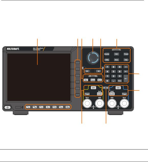
Front panel
1 |
2 3 |
4 |
5 |
6 |
7
8
|
|
|
|
|
|
|
|
|
|
|
|
|
|
|
|
|
|
|
|
|
|
|
|
|
|
|
|
|
|
|
|
|
|
13 |
12 |
10 |
9 |
||||
17 |
16 |
15 |
14 |
|
|
|
11 |
|
|
|
|||
|
|
|
|
Figure 3-1 Front Panel overview |
|
|
|
|
|||||
|
|
|
|
|
|
|
|
|
|
||||
1 |
|
Display Area |
Display user interface |
|
|
|
|
|
|
||||
2Menu Selection Includes 6 buttons to select the corresponding menu softkey
Button
3 |
Mode Button |
Modulation (Mod): Output modulation waveform |
|
Area |
Sweep: Scan a sine wave, square wave, ramp wave or |
|
|
arbitrary wave |
|
|
Burst: A burst that produces a sine wave, square wave, ramp |
|
|
wave, pulse wave, or arbitrary wave. |
|
|
|
4 |
Knob |
Change the currently selected value, also used to select the |
|
|
character in the soft keyboard when the file location or file |
|
|
name is entered. |
|
|
|
5 |
Direction Button |
Move the cursor of the selected parameter |
|
|
|
6 |
Function Button |
Counter: Enter the frequency meter interface |
Area |
|
|
Wave Edit (Edit): enter the waveform editing interface |
||
|
||
|
|
|
|
Preset: Enter the preset menu, set the reset parameters or |
|
|
|
|
|
3 |

3.Quick start
power-on parameters; save or read the settings file.
Utility: Set the auxiliary system function
Store: Save/recall arbitrary waveform data
|
|
Help: To get context help for any front panel button or menu |
||||||||
|
|
softkey, press the button and then press the button for which |
||||||||
|
|
you need help. |
|
|
|
|
|
|||
|
|
|
|
|
|
|
|
|
|
|
7 |
Numerical Keypad |
Input the parameter |
|
|
|
|
|
|||
|
|
|
|
|
|
|
|
|||
8 |
CH2 Button Area |
CH2 key: Enter the waveform interface and select the CH2 |
||||||||
|
|
channel (the backlight of the button lights up). After |
||||||||
|
|
selecting, the waveform and parameters of CH2 can be set. |
||||||||
|
|
|
|
|
|
|
|
|||
|
|
Blue Trigger button: CH2 manual trigger button. In sweep or |
||||||||
|
|
burst mode, when the trigger source is selected as “Manual”, |
||||||||
|
|
each press of this button will initiate a trigger. |
|
|||||||
|
|
|
|
|
|
|
|
|||
|
|
On/Off key: Turns the output of the CH2 channel on or off. |
||||||||
|
|
When the output is turned on, the backlight of the button |
||||||||
|
|
lights up. |
|
|
|
|
|
|||
|
|
|
|
|
|
|
|
|||
9 |
CH2 Sync Output |
|
|
|
|
|
|
|
|
|
When |
Utility |
→ |
CH1/2 Set |
→ |
CH2 Sync |
turned on, this |
||||
|
Terminal |
terminal outputs a sync signal that matches the current |
||||||||
|
|
|||||||||
|
|
configuration of CH2. |
|
|
|
|||||
|
|
|
|
|
|
|
|
|||
10 |
CH2 Output |
Output CH2 signal |
|
|
|
|
|
|||
|
Termnial |
|
|
|
|
|
|
|
|
|
|
|
|
||||||||
11 |
CH1 CH2 Button |
Display channel copy menu and menu of frequency |
||||||||
|
|
synchronization, |
amplitude |
synchronization, |
phase |
|||||
|
|
alignment, etc. |
|
|
|
|
|
|||
|
|
|
|
|
|
|
|
|||
12 |
CH1 Output |
Output CH1 signal |
|
|
|
|
|
|||
|
Terminal |
|
|
|
|
|
|
|
|
|
|
|
|
||||||||
13 |
CH1 Sync Output |
|
|
|
|
|
|
|
|
|
When |
Utility |
→ |
CH1/2 Set |
→ |
CH1 Sync |
turned on, this |
||||
|
Terminal |
terminal outputs a sync signal that matches the current |
||||||||
|
|
|||||||||
|
|
configuration of CH1. |
|
|
|
|||||
|
|
|
||||||||
14 |
CH1 Button Area |
CH1 key: Enter the waveform interface and select the CH1 |
||||||||
|
|
channel (the backlight of the button lights up). After |
||||||||
|
|
selecting, the waveform and parameters of CH1 can be set. |
||||||||
Yellow Trigger button: CH1 manual trigger button. In sweep or burst mode, when the trigger source is selected as “Manual”, each press of this button will initiate a trigger.
On/Off key: Turns the output of the CH1 channel on or off.
When the output is turned on, the backlight of the button
4

3.Quick start
lights up.
15 |
Waveform |
Including: sine |
|
, square |
, ramp |
, |
pulse |
|
Selection Area |
, noise |
, |
arbitrary wave |
, harmonic |
waves |
|
|
|
. When one waveform is selected, the corresponding |
|||||
|
|
backlight will be lit. |
|
|
|
|
|
|
|
|
|||||
16 |
USB Interface |
Connect to an external USB Host device, such as a USB flash |
|||||
|
|
drive. |
|
|
|
|
|
|
|
|
|
|
|
||
17 |
Power Button |
Turn on/off the waveform generator |
|
|
|
||
|
|
|
|
|
|
|
|
Rear Panel
1 |
2 |
10 |
|
|
|
|
|
|
|
|
|
|
|
|
|
|
|
|
|
|
|
|
|
|
|
|
|
|
|
|
|
9 |
|
|
|
|
|
|
|
|
|
|
|
3 |
||
|
|
|
|
|
|
|
|
|
|
|
||||
|
|
|
|
|
|
|
|
|
||||||
|
|
|
|
|
|
|
|
|||||||
|
|
|
|
|
|
|
|
4 |
||||||
|
|
|
|
|
|
|
||||||||
|
|
|
|
|
|
|
|
|
|
|
|
|
|
5 |
|
|
|
|
|
|
|
|
|
|
|
|
|
|
|
|
|
|
|
|
|
|
||||||||
|
|
|
|
|
|
|
|
|
|
|
|
|
||
|
|
|
|
|
|
|
|
|
|
|
|
|
|
|
|
8 |
7 |
6 |
|
|
|
|
|
|
|||||
|
|
Figure 3-2 Rear Panel Overview |
||||||||||||
|
|
|
|
|
|
|
|
|
|
|
|
|
||
1 |
Retractable Handle |
|
|
|
|
|
|
|
|
|
|
|
||
|
|
|
|
|
|
|
|
|
|
|
|
|
||
2 |
Vents |
|
|
|
|
|
|
|
|
|
|
|
||
|
|
|
||||||||||||
3 |
Power Input Socket |
AC power input interface. |
||||||||||||
|
|
|
||||||||||||
4 |
Fuse Box |
The place to install the fuse. |
||||||||||||
|
|
|
||||||||||||
5 |
Stool |
Tilting the signal generator for easy operation. |
||||||||||||
|
|
|
||||||||||||
6 |
LAN Interface |
The signal generator is connected to the local area |
||||||||||||
|
|
|
|
network through this interface for remote control. |
||||||||||
|
|
|
|
|
|
|
|
|
|
|
|
|
||
|
|
|
|
|
|
5 |
|
|
|
|
|
|
||
|
|
|
3.Quick start |
|
|
|
|
|
|
|
7 |
USB Device Interface |
Used to connect a USB type B controller. The PC |
|
|
|
|
can be connected to communicate with the signal |
|
|
|
|
generator through the host computer software. |
|
|
|
|
|
|
|
8 |
Keyhole |
A safety lock (please buy it yourself) can be used |
|
|
|
|
to lock the instrument in a fixed position to secure |
|
|
|
|
the instrument. |
|
910MHz
In/Out/Counter(Reference clock input / output / frequency meter input) connector
The default is to receive the frequency meter input signal. Used to receive a 10MHz clock signal when the instrument is set to an internal clock source
and Utility → System → CLK output is On; it is
used to receive an external 10MHz clock signal when the instrument is set to an external clock source.
10 Mod/FSK/Trig |
When modulating the waveform, outputting the |
(modulation/trigger |
sweep frequency, and the burst, the signal |
input) connector |
accessed here can be used as an external source. |
|
Note: If one channel turns on AM, FM, PM, PWM |
|
or OSK, and the other channel turns on ASK, FSK, |
|
PSK, sweep or burst, and both channels are set to |
|
external trigger, then the channel that sets the |
|
trigger source can be set later. With an external |
|
trigger, the other channel automatically cancels |
|
the external trigger because of the different |
|
external modulation signal types. |
|
|
Power On
(1)Connect the instrument to an AC power source using the power cord supplied with the accessory
Warning:
To prevent electric shock, make sure the instrument is properly grounded.
(2)Press the power button on the front panel and the screen will display the booting screen.
6

3.Quick start
User Interface
Figure 3-3 User Interface
1Display channel name and channel status
2Current waveform or current mode
3Trigger source.
Internal: internal modulation or internal trigger source External: external modulation or external trigger source Manual: manual trigger source
4Load, High Z indicates high resistance
5This icon is lit when the network is connected through the LAN
This icon is lit when connected to the USB Host via the USB DEVICE
6interface.
7When the instrument detects the USB flash drive, the icon lights.
8Current menu name
9Current waveform or mode setting menu
Frequency meter brief information, displays the frequency value,
10period and the duty value
11Display a schematic of the current waveform
12Display the current starting phase
13Offset / low level, depending on the right highlighted menu item
14Amplitude / high level, depending on the right highlighted menu item
7

3.Quick start
15 Frequency/cycle, depending on the right highlighted menu item
Use Build-in Help
(1)To get help on any front panel button or menu softkey, press the front panel Help function button first, then press the button you need help.
(2)Press the Help function key again to exit the help interface.
8

4.Panel Operation
4. Panel Operation
Channel Setting
Select the channel for configuration
Before configuring waveform parameters, you must select the channel you want to configure. Press CH1 or CH2 to select the corresponding channel, and the corresponding channel area in the user interface will light up
Turn On/Off Channel Output
Press the front panel CH1 On/Off or CH2 On/Off button to turn the output of the
corresponding channel on/off. When the output is turned on, the backlight of the button lights up.
Channel Copy
(1)Press CH1 CH2 on front panel to display copy menu.
(2)Select CH2 to CH1 softkey or CH1 to CH2 softkey to copy the channel.
Waveform Setting
Sine, square, ramp, pulse, noise, arbitrary or harmonic waves can be set and output. Press the waveform selection button on the instrument front panel: sine  , square
  , ramp
  , pulse
  , noise
  , arbitrary wave
  , harmonic
  , and enter the corresponding waveform setting interface. The waveform is different and the parameters that can be set are different.
Note: The following setting waveform uses CH1 channel as an example. If you need
to set CH2 channel, please refer to CH1 channel specific operation.
9
4.Panel Operation
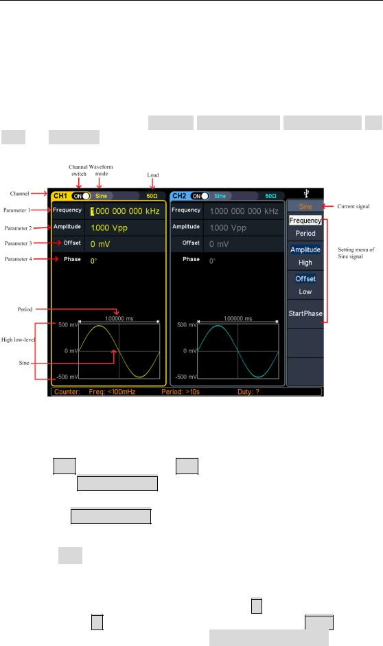
Output Sine Wave
Press  , the screen displays the user interface of the sine wave. By operating the sine wave menu on the right side of the screen, you can set the output waveform parameters of the sine wave.
The sine wave menu includes: frequency/period, amplitude/high level, offset/low level, and start phase. The menu can be operated by the menu selection button on the right.
Figure 4-1: Sine wave user interface
Set the frequency/period
Press CH1, all currently selected CH1 menu items are highlighted
Press the Frequency/Period soft key, the currently selected menu item is highlighted, and the corresponding parameter item is displayed in parameter 1. Press the Frequency/Period softkey again to switch the frequency and period.
There are two ways to change the selected parameter value:
Turn the knob to increase or decrease the value at the cursor. Press the  /
/ arrow key to move the cursor left or right.
Press a number key on the numeric keypad directly, the screen will pop out the data input box, input the desired value. Press the X soft key to delete the last digit, press the ← soft key to cancel the input, and press the Enter soft key to indicate the default unit input. Press the MHz, kHz, Hz, mHz, mHz soft keys to
10

4.Panel Operation
select the unit of the parameter. Press the Cancel softkey to cancel the current input parameter value.
Figure 4-2: Use the numeric keypad to set the frequency
Set the amplitude
Press the Amplitude/High Level softkey to confirm whether the Amplitude menu item is highlighted; if not, press the Ampl/High button to switch to Amplitude. In parameter 2 of Figure 5-1, the parameter value of the amplitude appears as a blinking cursor. Use the knob or numeric keypad to set the desired value.
Set the offset
Press the Offset/Low Level softkey to confirm whether the Offset menu item is highlighted; if not, press the Offset/Low level key to switch to Offset. In parameter 3 of Figure 5-1, the parameter value of the offset appears as a blinking cursor. Use the knob or numeric keypad to set the desired value.
Set the high level
Press the Amplitude/High level button to confirm whether the “High level” menu item is highlighted; if not, press the Ampl/High level button to switch to “High level”. In parameter 2 of Figure 5-1, a high-level parameter value appears as a blinking cursor. Use the knob or numeric keypad to set the desired value.
Set the low level
Press the Off/Low level button to confirm whether the “Low level” menu item is highlighted; if not, press the Offset/Low level button to switch to “Low level”. In
11
4.Panel Operation
parameter 3 of Figure 5-1, a low-level parameter value appears as a blinking cursor. Use the knob or numeric keypad to set the desired value.
Set the start phase
Press the Start Phase softkey to confirm whether the Start Phase menu item is highlighted; if not, press the Start Phase key. In parameter 4 of Figure 5-1, the parameter value of the starting phase appears as a blinking cursor. Use the knob or numeric keypad to set the desired value
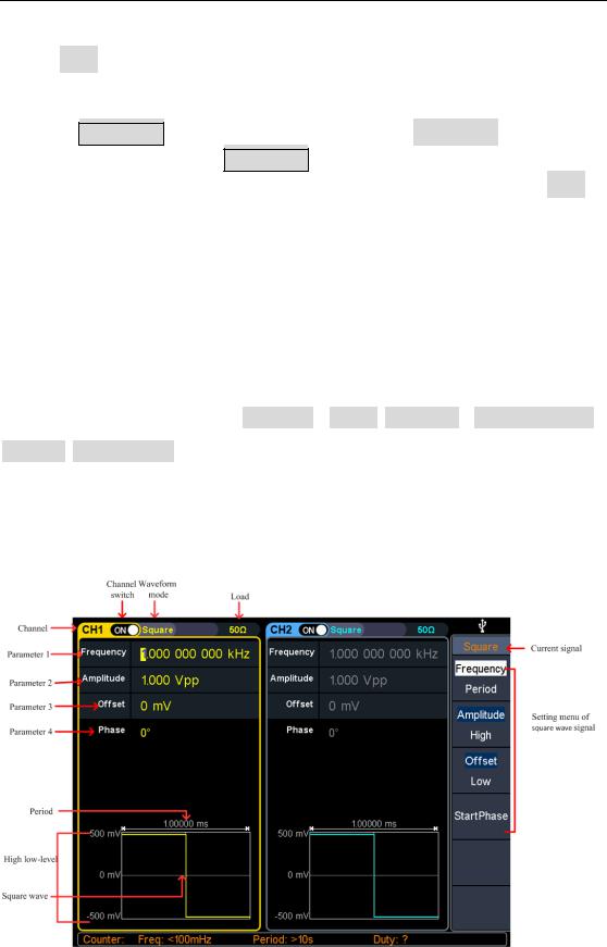
Output Square Wave
Press  , the screen displays the square wave user interface. By operating the square wave menu on the right side of the screen, you can set the square wave output waveform parameters.
The square wave menu includes: frequency / period, amplitude / high level, offset / low level, starting phase.
For the setting frequency/period, amplitude/high level, offset/low level, and starting phase, please refer to Output Sine Wave on page 10.
Figure 4-3: Square wave user interface
12
4.Panel Operation
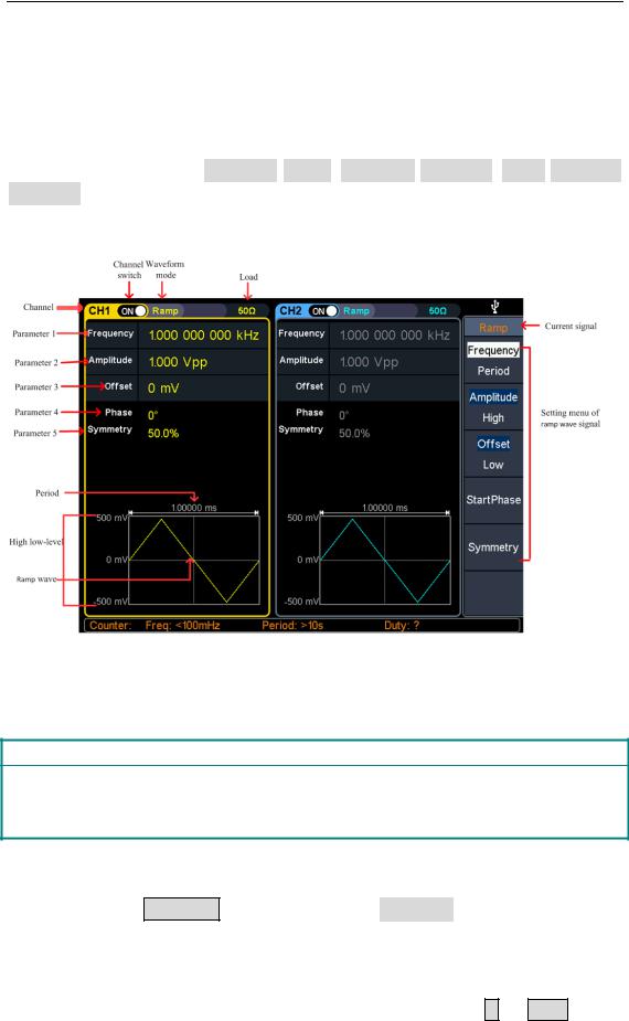
Output Ramp Wave
Press  , the screen displays the user interface of the ramp wave. By operating
the ramp menu on the right side of the screen, you can set the output waveform parameters of the ramp wave.
The ramp menu includes: frequency/period, amplitude/high level, offset/low level, symmetry.
For the setting frequency/period, amplitude/high level, offset/low level, and starting phase, please refer to Output Sine Wave on page 10.
Figure 4-4: Ramp wave user interface
Glossary
Symmetry: Sets the percentage of the period during which the ramp waveform is rising.
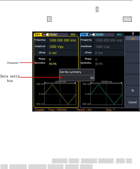
Set the symmetry
(1)Press the Symmetry softkey to select the Symmetry menu item. Figure 5-6
Parameter 1 shows the current value of the symmetry;
(2)Use the knob to change directly, the value in parameter 1 of Figure 5-6; Or use the numeric keypad to enter the value, press the % or Enter key to
13
4.Panel Operation
display the symmetrical value of the input, press the X soft key to delete the
last digit, press the ← soft key to cancel the input, and press the Enter
softkey to indicate the default input.
Figure 4-5: Set the symmetry of ramp wave
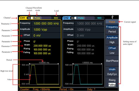
Output Pulse Wave
Press  , the screen displays the user interface of the pulse wave. By operating
the pulse wave menu on the right side of the screen, the output waveform parameters of the pulse wave can be set.
The pulse wave menu includes: frequency/period, amplitude/high level, offset/low level, start phase, pulse width/duty cycle, rise time/fall time.
For the setting frequency/period, amplitude/high level, offset/low level, and starting phase, please refer to Output Sine Wave on page 10.
14
4.Panel Operation
Figure 4-6: Pulse wave user interface
15
4.Panel Operation
Glossary
Pulse Width
PW is an abbreviation for pulse width and is divided into positive pulse width and negative pulse width.
The positive pulse width is the time interval from 50% of the rising edge to 50% of the adjacent falling edge.
The negative pulse width is the time interval from 50% of the falling edge to 50% of the adjacent rising edge.
The pulse width is determined by the period and duty cycle of the signal. The calculation formula is pulse width = period * duty cycle.
Duty Cycle
In a series of ideal pulse sequences (such as a square wave), the ratio of the duration of the positive pulse to the total pulse period.
Pulse/Duty Cycle
The pulse width is defined as the time interval from the 50% threshold of the amplitude of the rising edge of the pulse to the 50% threshold of the amplitude of the next falling edge, as shown in the following figure.
The settable range of pulse width is limited by the "minimum pulse width" and "pulse period"
Pulse width ≥ minimum pulse width
Pulse width ≤ pulse period - minimum pulse width
The pulse duty cycle is defined as the pulse width as a percentage of the pulse period.
The pulse duty cycle is associated with the pulse width, and modifying one of the parameters will automatically modify the other parameter. The pulse duty cycle is limited by the "minimum pulse width" and "pulse period".
Pulse duty cycle ≥ minimum pulse width ÷ pulse period × 100%
Pulse duty cycle ≤ (1 - 2 × minimum pulse width ÷ pulse period) × 100%
16
4.Panel Operation
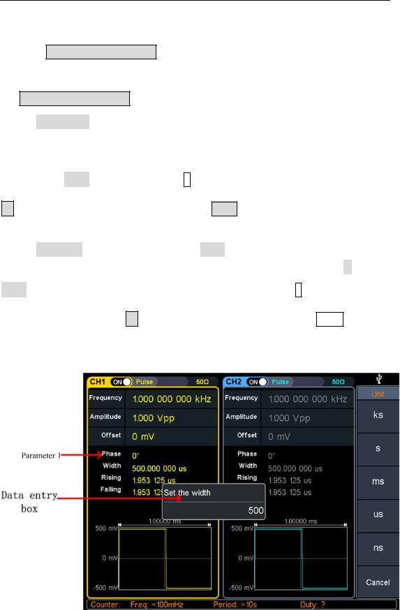
Set the pulse width/duty cycle
Press the Pulse Width/Duty Cycle softkey to select the Pulse Width menu item. As
shown in Figure 5-7, parameter 1 displays the current value of the pulse width. Press
the Pulse Width/Duty Cycle button to display the duty cycle.
Set the pulse width parameter value, use the knob to directly change the value of
the pulse width in parameter 1 of Figure 5-7; or use the numeric keypad to enter the value, then select the desired unit from the right menu, press the desired unit (ks, s,
ms, us, ns) or Enter the value; press the X soft key to delete the last digit, press the
← soft key to cancel the input, and press the Enter soft key to indicate the default
input.
Set the duty cycle parameter value, use the knob to directly change the value of the
graph duty cycle; or use the numeric keypad to enter the value, then press % or
Enter from the right menu to enter the demand value; press the X soft key to delete
the last one. Bit, press the ← soft key to cancel the input, press the Enter soft key
to indicate the default input.
Figure 4-7: Set the pulse width
17
4.Panel Operation
Set the rising/falling time
Press the rise time / fall time soft key to select the "rise time / fall time" menu item,
as shown in Figure 5-6, parameter 6 shows the current value of the rise/fall time; press the rise time / fall time key to switch between the current display. Parameter value.
Set the rise time/fall time parameter value Use the knob or use the numeric keypad to enter the value, then select the desired unit from the right menu, press the
desired unit (ks, s, ms, us, ns) or Enter the value; press the X soft key to delete the
last digit, press the ← soft key to cancel the input, press the Enter softkey to
indicate the default input.
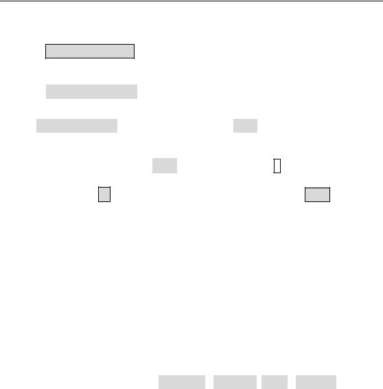
Output Noise Wave
The noise wave output by the system is white noise. Press  , the screen displays
the user interface of the noise wave. By operating the noise wave menu on the right side of the screen, the output waveform parameters of the noise wave can be set.
The noise wave has no frequency and periodic parameters, and the bandwidth is 120 MHz of Gaussian noise.
The menu of noise waves includes: amplitude / high level, offset / low level.
For the setting of amplitude/high level, offset/low level, please refer to Output Sine Wave on page 10.
18

4.Panel Operation
Figure 4-8: noise wave user interface
Output Arbitrary Wave
Press  , the screen displays the user interface of the arbitrary wave. By
operating the arbitrary wave menu on the right side of the screen, the output waveform parameters of the arbitrary wave can be set.
Arbitrary wave menus include: frequency/period, amplitude/high level, offset/low level, start phase, built-in waveform.
For the setting frequency/period, amplitude/high level, offset/low level, and starting phase, please refer to Output Sine Wave on page 10.
Arbitrary waves include two kinds of arbitrary waveforms: system built-in waveforms and user-edited waveforms.
19
Loading...