


 Loading...
VOLTCRAFT DSO-1084E, DSO-1104E, DSO-1204E, DSO-1254E, DSO-1084F User guide
...DSO1000E/F Series
Digital Storage Oscilloscope
User Manual
(Version 1.3)

Copyright Declaration
All rights reserved; no part of this document may be reproduced or transmitted in any form or by any means, electronic or mechanical, without prior written permission from our company.
Our company reserves all rights to modify this document without prior notice. Please contact our company for the latest version of this document before placing an order. Our company has made every effort to ensure the accuracy of this document but does not guarantee the absence of errors. Moreover, Our company assumes no responsibility in obtaining permission and authorization of any third party patent, copyright or product involved in relation to the use of this document.
Digital Storage Oscilloscope |
I |

General Safety Summary
Read the following safety precautions to avoid injury and prevent damage to this product or any products connected to it. To evade potential hazards, use this product only as specified.
Only qualified personnel should perform maintenance. Avoid fire or personal injury.
Use suitable power cord. Use only the power cord specified for this product and certified for the country of use.
Connect and disconnect properly. Connect a probe with the oscilloscope before it is connected to measured circuits; disconnect the probe from the oscilloscope after it is disconnected from measured circuits.
Ground the product. This product is grounded through the grounding conductor of the power cord. To avoid electric shock, the grounding conductor must be connected to earth ground. Before making connections to the input or output terminals of the product, ensure that the product is properly grounded.
Connect the probe in a right way. The probe ground lead is at ground potential. Do not connect the ground lead to an elevated voltage.
Check all terminal ratings. To avoid fire or shock hazard, check all ratings and markings on the product. Refer to the product manual for detailed information about ratings before making connections to the product.
Do not operate without covers. Do not operate this product with covers or panels removed.
Avoid exposed circuitry. Do not touch exposed connections and components when power is present.
Do not operate with suspected failures. If you suspect there is damage to this product, have it inspected by qualified service personnel.
Assure good ventilation.
Do not operate in wet/damp environments. Do not operate in an explosive atmosphere. Keep product surfaces clean and dry.
Digital Storage Oscilloscope |
II |

Safety Terms and Symbols
Terms on the product. The following terms may appear on the product:
Danger It represents that harms may be caused to you at once if you perform the operation.
Warning It represents that latent harms may be caused to you if you perform the operation.
Notice It represents the damage possibly caused to the product or other properties if you perform the operation.
Characters on the product. The following characters may appear on the product:
Notice |
Protective |
Measuring |
Chassis |
Please read |
ground terminal |
ground terminal |
ground terminal |
the manual |
|
|
|
|
|
|
|
Product Scrapping
Device Recycling
We need extract and utilize natural resources to produce this device. If you do not reclaim the device in a proper way, some substances it contains may become harmful or poisonous to environments or human bodies. To avoid them being released outside and to minimize the waste of natural resources, we suggest you reasonably call back this device to ensure proper recovery and recycling of most materials within it.
Digital Storage Oscilloscope |
III |

Brief Introduction to the Series of digital
storage oscilloscope
DSO1000E/F Series oscilloscopes cover the bandwidths from 80MHz to 200MHz, and provide the real-time up to 1GSa/s. In addition, they have 7 inch color TFT LCD as well as WINDOWS-style interfaces and menus for easy operation.
What’s more, the plenty menu information and the easy-to-operate buttons allow you to gain information as much as possible in measurement; the multifunctional knobs and the powerful shortcut keys help you save a lot of time in operation; the Auto Scale function lets you detect sine and square waves automatically; By using the three methods the oscilloscope provides (context-sensitive, hyperlinks, and an index), you may master all operations on the device in quite a short time so as to greatly improve your efficiency in production and development.
Model |
Channels |
Bandwidth |
Sample Rate |
AFG |
DSO-1084E |
4 |
80MHz |
1GS/s |
- |
|
|
|
|
|
DSO-1104E |
4 |
100MHz |
1GS/s |
- |
|
|
|
|
|
DSO-1204E |
4 |
200MHz |
1GS/s |
- |
|
|
|
|
|
DSO-1254E |
4 |
250MHz |
1GS/s |
- |
|
|
|
|
|
DSO-1084F |
4 |
80MHz |
1GS/s |
Yes |
|
|
|
|
|
DSO-1104F |
4 |
100MHz |
1GS/s |
Yes |
|
|
|
|
|
DSO-1204F |
4 |
200MHz |
1GS/s |
Yes |
|
|
|
|
|
DSO-1254F |
4 |
250MHz |
1GS/s |
Yes |
|
|
|
|
|
Digital Storage Oscilloscope |
IV |

|
Contents |
|
Copyright Declaration................................................................................................ |
I |
|
General Safety Summary ....................................................................................... |
II |
|
Safety Terms and Symbols .................................................................................... |
III |
|
Product Scrapping................................................................................................. |
III |
|
Brief Introduction to the Series of digital storage oscilloscope............................... |
IV |
|
Contents ................................................................................................................... |
|
V |
Chapter 1 |
Introduction........................................................................................ |
1 |
1.1 |
General Inspection ................................................................................... |
2 |
1.2 |
Prepare Instrument for Use....................................................................... |
3 |
1.3 |
Accidence of the user interface................................................................. |
4 |
1.4 |
Functional Check...................................................................................... |
5 |
1.4.1 |
Connect the oscilloscope...................................................................... |
5 |
1.4.2 |
Observe the waveform ......................................................................... |
5 |
1.5 |
Probe Introduction .................................................................................... |
6 |
1.5.1 |
Safety................................................................................................... |
6 |
1.5.2 |
Probe Check Wizard............................................................................. |
6 |
1.5.3 |
Manual Probe Compensation ............................................................... |
6 |
1.5.4 |
Probe Attenuation Setting..................................................................... |
7 |
Chapter 2 |
Function Introduction ........................................................................ |
9 |
2.1 |
Menu and Control Keys .......................................................................... |
10 |
2.2 |
Connector............................................................................................... |
11 |
2.3 |
Universal Knobs and Softkeys ................................................................ |
11 |
2.4 |
Oscilloscope Setup................................................................................. |
12 |
2.5 |
Horizontal Controls ................................................................................. |
13 |
2.6 |
Vertical System....................................................................................... |
14 |
2.6.1 |
Vertical Controls ................................................................................. |
14 |
2.6.2 |
Math Operation................................................................................... |
16 |
2.7 |
Trigger System ....................................................................................... |
20 |
|
Digital Storage Oscilloscope |
V |
2.7.1 |
|
Edge Trigger....................................................................................... |
22 |
2.7.2 |
|
Pulse Trigger ...................................................................................... |
22 |
2.7.3 |
|
Video Trigger...................................................................................... |
24 |
2.7.4 |
|
Slope Trigger...................................................................................... |
25 |
2.7.5 |
|
Overtime Trigger................................................................................. |
26 |
2.7.6 |
|
Window Trigger .................................................................................. |
27 |
2.7.7 |
|
Pattern Trigger.................................................................................... |
27 |
2.7.8 |
|
Interval Trigger ................................................................................... |
29 |
2.7.9 |
|
Under Amp Trigger ............................................................................. |
30 |
2.7.10 |
UART Triggering................................................................................. |
31 |
|
2.7.11 |
LIN Triggering..................................................................................... |
34 |
|
2.7.12 |
CAN Triggering................................................................................... |
35 |
|
2.7.13 |
SPI Triggering..................................................................................... |
36 |
|
2.7.14 |
IIC Trigger .......................................................................................... |
37 |
|
2.8 |
Save/Recall ............................................................................................ |
39 |
|
2.8.1 |
|
Internal Save and Recall..................................................................... |
40 |
2.8.2 |
|
External save and recall ..................................................................... |
41 |
2.9 |
Measure System..................................................................................... |
42 |
|
2.9.1 |
|
Scale measurement............................................................................ |
42 |
2.9.2 |
|
Cursor measurement.......................................................................... |
42 |
2.9.3 |
|
Automatic Measurement..................................................................... |
43 |
2.10 |
Acquire ................................................................................................... |
47 |
|
2.10.1 |
XY Mode ............................................................................................ |
50 |
|
2.10.2 |
Roll Mode ........................................................................................... |
51 |
|
2.11 |
Display ................................................................................................... |
51 |
|
2.12 |
Utility System.......................................................................................... |
52 |
|
2.12.1 |
Update Firmware................................................................................ |
52 |
|
2.12.2 |
Self Calibration................................................................................... |
53 |
|
2.12.3 |
Pass/Fail ............................................................................................ |
53 |
|
2.13 |
Fast Action Buttons................................................................................. |
54 |
|
2.13.1 |
AUTO SCALE..................................................................................... |
55 |
|
2.13.2 |
Default Setup...................................................................................... |
56 |
|
|
|
|
|
|
|
Digital Storage Oscilloscope |
VI |

Chapter 3 |
Waveform Generator........................................................................ |
59 |
3.1 |
Set Wave Type and Parameters ............................................................. |
59 |
3.2 |
Edit Arbitrary Waveform .......................................................................... |
60 |
3.3 |
Output Arbitrary Waveform...................................................................... |
62 |
Chapter 4 |
Troubleshooting............................................................................... |
63 |
4.1 |
Problem Settlement ................................................................................ |
63 |
Chapter 5 |
General Care and Cleaning ............................................................. |
65 |
5.1 |
General Care.......................................................................................... |
65 |
5.2 |
Cleaning ................................................................................................. |
65 |
Appendix A: Technical Specifications ................................................................... |
66 |
|
Appendix B: Accessories ....................................................................................... |
73 |
|
Appendix C Harmful and Poisonous Substances or Elements............................ |
74 |
|
Appendix D To replace the fuse........................................................................... |
75 |
|
Appendix E Open Source Information............................................................ |
77 |
|
Digital Storage Oscilloscope |
VII |

Chapter 1 Introduction
General Inspection
Prepare Instrument for Use
Accidence of the user interface
Functional Check
Probe Introduction
Digital Storage Oscilloscope |
1 |

1.1 General Inspection
Please check the instrument as following steps after receiving an oscilloscope:
Check the shipping container for damage:
Keep the damaged shipping container or cushioning material until the contents of the shipment have been checked for completeness and the instrument has been checked mechanically and electrically.
Check the accessories:
Accessories supplied with the instrument are listed in "Accessories" in this manual. If the contents are incomplete or damaged, please notify the franchiser.
Check the instrument:
In case there is any mechanical damage or defect, or the instrument does not operate properly or fails performance tests, please notify the franchiser.
Digital Storage Oscilloscope |
2 |
1.2 Prepare Instrument for Use
Adjust the Supporting Legs
Adjust the supporting legs properly to use them as stands to tilt the oscilloscope upwards for stable placement of the oscilloscope as well as better operation and observation.
Connect the Power Cord
Connect the power cord as desired. Turn the instrument on by pressing the power switch in the lower left corner of front panel.
If the instrument does not turn on, verify that the power cord is firmly connected (power-line voltage is automatically sensed at power-on). Also make sure that the instrument is connected to an energized power source.
Power Switch:
To turn off the instrument, please press power switch.
Digital Storage Oscilloscope |
3 |
1.3 Accidence of the user interface
This section will make you understand the front operation panel of this series of digital oscilloscope at first before use.
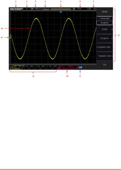
Figure 1-2 Interface display
1.Voltcraft logo
2.Trigger Status
Auto: The oscilloscope works in auto mode and is acquiring waveforms in the absence of triggers.
Ready: All pre-triggered data have been acquired and the oscilloscope is ready to accept a trigger.
Roll: The oscilloscope is acquiring and displaying waveform data continuously in roll mode.
Stop: The oscilloscope has stopped acquiring waveform data.
3.Readout shows main time base setting.
4.Sample rate.
5.Main Time Base Window
Digital Storage Oscilloscope |
4 |
6.Tigger time
7.Trigger level, Readout tells trigger level.
8.Operating Menu shows different information for respective function keys.
9.If this icon lights up/active, it means the USB disk has been connected.
10.If this icon lights up/active, it means the wave generator works
11.The information of coupling, Bandwidth and volt/div of CH1~CH4.
12.Channel Marker
13.Window displays waveform.
1.4 Functional Check
Follow the steps below to perform a quick functional check to your oscilloscope.
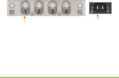
1.4.1Connect the oscilloscope
Set the switch on the probe to 10X and connect the probe to Channel 1 on the oscilloscope. First, align the slot in the probe connector with the protuberance on the CH1 BNC and push to connect; then, turn to right to lock the probe in place; after that, connect the probe tip and reference lead to the PROBE COMP connectors. There is a mark on the panel: Probe COMP ~2V@1KHz.
CH1: to connect with the probe |
PROBE COMP |
|
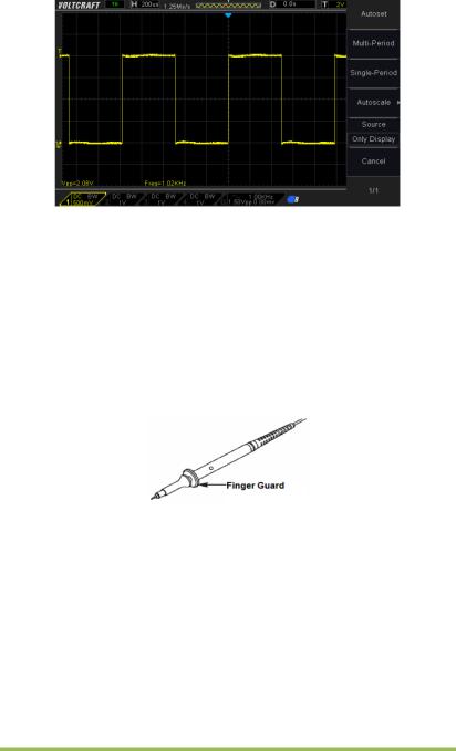
1.4.2Observe the waveform
Press the [Auto Scale] button and you should see within a few seconds a square wave of about 2V peak-to-peak at 1KHz in the display. Press the CH1 MENU button twice to remove Channel 1. Push the CH2 MENU button and repeat the steps to observe CH2, CH3 and CH4.
Digital Storage Oscilloscope |
5 |
1.5 Probe Introduction
1.5.1Safety
When using the probe, keep your fingers behind the guard on the probe body to avoid electric shock. Do not touch metallic portions of the probe head while it is connected to a voltage source. Connect the probe to the oscilloscope and connect the ground terminal to ground before you start any measurements.
1.5.2Probe Check Wizard
Every time you connect a probe to an input channel, you should use the probe check wizard to verify that this probe is operating correctly.
Use the vertical menu (for example, push the CH1 MENU button) to set the Probe attenuation factor.
1.5.3Manual Probe Compensation
Upon the first connection of a probe and an input channel, you should manually perform this adjustment to match the probe to the input channel. Uncompensated or
Digital Storage Oscilloscope |
6 |
miscompensated probes may lead to errors or faults in measurement. To adjust the probe compensation, follow the steps below.
1.Set the Probe option attenuation in the channel menu to 10X. Set the switch on the probe to 10X and connect the probe to Channel 1 on the oscilloscope. If you use the probe hook-tip, ensure it is firmly inserted onto the probe. Attach the probe tip to the PROBE COMP ~2V@1KHz connector and the reference lead to the PROBE COMP Ground connector. Display the channel and then press the Auto Scale button.
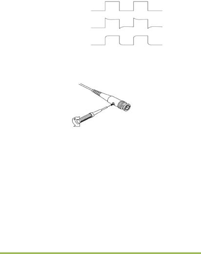
2.Check the shape of the displayed waveform.
Compensated correctly
Overcompensated
Undercompensated
3.If necessary, use a nonmetallic screwdriver to adjust the variable capacity of your probe until the shape of the waveform turns to be the same as the above figure. Repeat this step as necessary. See the figure below for the way of adjustment.
1.5.4Probe Attenuation Setting
Probes are of various attenuation factors which affect the vertical scale of the signal. The Probe Check function is used to verify if the Probe attenuation option matches the attenuation of the probe.
You can push a vertical menu button (such as the CH1 MENU button) and select the Probe option that matches the attenuation factor of your probe.
Make sure that the Attenuation switch on the probe matches the Probe option in the oscilloscope. Switch settings are 1X and 10X.
When the Attenuation switch is set to 1X, the probe limits the bandwidth of the oscilloscope to 6MHz. To use the full bandwidth of the oscilloscope, be sure to set the
Digital Storage Oscilloscope |
7 |

switch to 10X.
Digital Storage Oscilloscope |
8 |

Chapter 2 Function Introduction
This chapter provides some general information that you need to learn before using an oscilloscope. It contains:
Menu andCcontrol Keys
Connector
Universal Knobs and Softkeys
Oscilloscope Setup
Horizontal Controls
Vertical System
Trigger System
Save/Recall
Measure System
Acquire
Display
Utility System
Fast Action Buttons
Digital Storage Oscilloscope |
9 |

2.1 Menu and Control Keys
As shown in the figure below:
Figure 2-1 Control keys
All the keys are described as follows:
[CH1], [CH2], [CH3], [CH4]: display setup menus of channel 1 and channel 2.
[Math]: display “Arithmetical operation” waveform menu.
[Horizontal]: Set Horizontal system.
[Trig Menu]: display Trigger control menu.
[Force Trig]: It is used for finishing acquisition of the current waveform no matter whether the oscilloscope detects trigger, and it is mainly applied to “Normal” and “Single” in the trigger mode.
[Default]: recall the default factory setup.
[Help]: enter the on-line help system.
[Utility]: display “UTILITY FUNCTION” menu.
[Cursors]: display the “CURSOR” menu. The [V0] knob can be used for regulating the position of the cursor when the “CURSOR” menu is displayed and the cursor is triggered.
[Meas]: show the “Measure” menu.
[Wave Gen]: show the waveform generator menu.
[Save Recall]: show the “Save/Recall” menu of setups and waveform.
[Display]: show the “Display” menu.
[Auto Scale]: automatically set the control state of the oscilloscope so as to display suitable waveform.
Digital Storage Oscilloscope |
10 |

[Run/Stop]: continuously acquire waveform or stop acquisition
[Single]: Acquire a single trigger, finish acquisition and then stop.
2.2 Connector
Figure 2-2 Connector
CH1, CH2, CH3, CH4: for an input connector of a measured signal.
EXT TRIG: be used as an input connector of an external trigger source. Use [Trig Menu] button to select “External” trigger source (only for Edge trigger), and the trigger signal source can be used for triggering in the third channel while acquiring data.
Gen Out: Waveform signal output.
Probe compensation: The probe compensation signal is output and grounded so that the probe is matched with the channels of the oscilloscope.
2.3 Universal Knobs and Softkeys
V0: Universal Knob. Under different menu options, it supports selecting menu options (MEASURE), moving cursors and levels (Slope Trigger). Press this knob to reset data (trigger holdoff, overtime of the overtime trigger and slope trigger), select menu options and so on. Easy to operate.
Press the Wave Gen button on the front panel to open the arbitrary waveform generator function.
Digital Storage Oscilloscope |
11 |

 Hide/Show softkey. Push it to hide the menu options on the right side of the screen and give a full screen display of waveforms. Push it again to show the menu options.
F1-F5: These five softkeys are all multi-functional. They are in charge of selecting corresponding menu options on the screen in different menu modes.
 This functional softkey is mainly used to turn pages and confirm a selection, such as ‘next page’, ‘previous page’.
2.4 Oscilloscope Setup
While operating the oscilloscope, you may often use three features: Auto Scale, saving a setup and recalling a setup. Hereinafter they are introduced one by one.
Auto Scale: This function can be used to adjust the horizontal and vertical scales of the oscilloscope automatically and set the trigger coupling, type, position, slope, level and mode, etc., to acquire a stable waveform display.
Saving a Setup: By default, the oscilloscope will save the setup each time before being closed, and automatically recall the setup once being turned on. (Note: If you modify the setup, please wait for more than 1 second before turning off the oscilloscope to ensure the proper storage of new settings.) You can save 10 settings permanently in the oscilloscope and reset them as necessary.
Recalling a Setup: The oscilloscope can recall any of your saved setups or the default factory setup.
Default Setup: The oscilloscope is preset for normal operations when it is shipped from the factory. This is the default setup. You may recall this setup at any time for your requirements.
Digital Storage Oscilloscope |
12 |
2.5 Horizontal Controls
Use the horizontal controls to change the horizontal scale and position of waveforms. The horizontal position readout shows the time represented by the center of the screen, using the trigger time as zero. When you change the horizontal scale, the waveform will expand or contract to the screen center. The readout near the upper right of the screen shows the current horizontal position in second. The oscilloscope also has an arrow icon at the top of the graticule to indicate the horizontal position.
1. Horizontal Position Knob: Used to control the trigger position against the screen center. Push this button to reset the trigger point back to the screen center.
AN: Used to set the horizontal position as zero.
Universal Knob
2.SEC/DIV Knob: Used to change the horizontal time scale so as to magnify or compress the waveform horizontally. If the waveform acquisition is stopped (by using the [Run/Stop] or [Single] button), the SEC/DIV control will expand or compress the waveform.
Note: Press SEC/DIV Knob to enter Dual-window Mode.
Digital Storage Oscilloscope |
13 |
Single-window Mode
Dual-window Mode (Full Screen)
Location of expanded window data in memory
Major Window
Minor Window
(Expanded Window)
Press SEC/DIV Knob again to exit Dual-window Mode.
2.6 Vertical System
2.6.1Vertical Controls
Vertical controls can be used to display and remove waveforms, adjust vertical scale and position, set input parameters and perform math calculations. Each channel has a separate vertical menu to set. See below for menu description.
Digital Storage Oscilloscope |
14 |

Vertical Position
Volts/div
1.Vertical Position Knob: Move the channel waveform up and down on the screen. In dual-window mode, move the waveforms in both windows at the same time in a same direction. Push this knob to return waveforms to the vertical center position on the screen. Two channels correspond to two knobs.
2.VOLTS/DIV Knob
Control the oscilloscope to magnify or attenuate the source signal of the channel waveform. The vertical size of the display on the screen will change (increase or decrease) to the ground level. Also you may use this knob to switch between coarse and fine.
3.Menu (CH1, CH2, CH3, CH4): Display vertical menu options; turn on or off the display of channel waveforms.
Options |
Settings |
Comments |
|
|
|
DC Coupling AC
GND
DC passes both DC and AC components of the input signal.
AC blocks the DC component of the input signal and attenuates signals below 10Hz.
Ground disconnects the input signal.
|
BW 20MHz |
OFF |
Limits the bandwidth to reduce display noise; filters |
||
|
the signal to eliminate noise and other unnecessary |
||||
|
ON |
||||
|
|
HF components. |
|
|
|
|
|
|
|
|
|
|
|
|
|
|
|
|
|
Coarse |
Selects the resolution of the VOLTS/DIV knob. |
|
|
|
Div |
Coarse defines a 1-2-5 sequence. Fine changes the |
|||
|
Fine |
resolution to small steps between the Coarse |
|||
|
|
||||
|
|
|
settings. |
|
|
|
|
|
|
|
|
|
|
1X |
Selects a value according to the probe attenuation |
||
|
|
10X |
|||
|
Probe |
factor so as to ensure correct vertical readouts. |
|||
|
100X |
||||
|
|
Reduce bandwidth to 6MHz when using a 1X probe. |
|||
|
|
1000X |
|||
|
|
|
|
|
|
|
|
|
|
|
|
|
|
|
|
|
|
|
|
|
Digital Storage Oscilloscope |
15 |
|

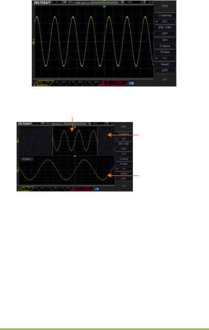
Invert |
OFF |
|
ON |
||
|
The invert function turns the displayed waveform 180 degrees, with respect to the ground level. When the oscilloscope is triggered on the inverted signal, the trigger is also inverted.
Coupling
If the channel adopts a DC coupling mode, you can quickly measure the DC component of the signal by observing the difference between the waveform and the signal ground.
If the channel adopts an AC coupling mode, the DC component in the signal is filtered. By this mode, the AC component of the signal is displayed at a higher sensitivity.
If the channel adopts a GND coupling mode, cut off the input signal. Inside the channel, the channel input is connected with a zero volt reference electric level.
Fine Resolution
In the fine resolution setting, the vertical scale readout displays the actual VOLTS/DIV setting. The vertical scale changes only after you adjust the VOLTS/DIV control and set to coarse.
Remove Waveform Display
To remove a waveform from the screen, first push the menu button to display the vertical menu, then push again to remove the waveform. A channel waveform which is unnecessary to be displayed can be used as a trigger source or for math operations.
2.6.2Math Operation
The series of scope supports many math operations between analog channels waveforms, including addition (+), subtraction (-), multiplication (*), division (/) and FFT. You can use cursors to measure it. The contents of this chapter:
•Units for Math Waveforms
•Math Operators
•To Adjust the Math Waveform Scale and Offset
Note: If the analog channel or the math function display is truncated (waveforms do not display on the screen completely), the resulting math will also be truncated.
Operation |
Unit |
|
|
Digital Storage Oscilloscope |
16 |

Addition (+)or subtraction (-) |
V |
|
|
multiplication (*) |
V 2 |
|
|
division (/) |
None |
|
|
FFT |
dB, Vrms, |
|
|
Addition or Subtraction
Math operators perform arithmetic operations - add or subtract operation - on any two analog input channels. When you select addition or subtraction, the Source A and Source B values are added or subtracted point by point, and the result is displayed.
1.Press the [Math] button on the front panel to enter the MATH function menu.
2.Press the Source 1 and Source 2 softkey respectively, and then turn the Universal Knob to select the source to do math operation. Analog channels (CH1~CH4) can be used as Source 1 or source 2.
3.Press the Operation softkey and then turn the universal to select + or -to make addition or subtraction operation. The resulting math waveform is displayed on the screen and labeled with “M”.
Scale: Press the Scale softkey, and then turn the Universal Knob to select the vertical scale.
Digital Storage Oscilloscope |
17 |

Multiplication and Division
Math operators perform arithmetic operations multiplication or division operation on any two analog input channels. When you select multiplication or division, the Source 1 and Source 2 values are multiplied or divided point by point and the result is displayed.
1.Press the [Math] button on the front panel to enter the MATH function menu.
2.Press the Source 1and Source 2 softkey respectively, and then turn the Universal Knob to select the source to do math operation. Analog channels (CH1 ~CH4) can be used as Source 1 or source 2.
3.Press the Operation softkey and then turn the universal to select * or / to make multiplication or division operation. The resulting math waveform is displayed on the screen and labeled with “M”.
Scale: Press the Scale softkey, and then turn the Universal Knob to select the vertical scale.
FFT Operation
FFT is used to compute the fast Fourier transform using analog input channels or reference waveforms. FFT takes the digitized time record of the specified source and transforms it to the frequency domain. When the FFT function is selected, the FFT spectrum is plotted on the oscilloscope display as magnitude in dBV versus frequency. The readout for the horizontal axis changes from time to frequency (Hertz) and the vertical readout changes from volts to dB. FFT operation can facilitate the following works:
Measure harmonic components and distortion in the system
Measure the characteristics of the noise in DC power
Analyze vibration
To display a FFT waveform:
1.Press the [Math] button on the front panel to open the MATH function menu.
2.Press the Operation softkey and then turn the Universal Knob to select FFT. The resulting math waveform is displayed on the screen and labeled with “M”.
3.Press the Source softkey, and then turn the Universal Knob to select the source to do FFT operation. Analog channels (CH1~CH4) can be used as the source.
Digital Storage Oscilloscope |
18 |
4.Press Center softkey and then turn the Universal Knob to adjust the frequency of the frequency domain waveform corresponding to the horizontal center of the screen.
5.Press Span softkey and then turn the Universal Knob to adjust the the horizontal scale of the frequency domain waveform.
6.Press the Vertical Units softkey to select the unit of vertical axis. The units of the vertical axis can be dB or Vrms which use a logarithmic scale or a linear scale to display vertical amplitude respectively. If you need to display the FFT frequency spectrum in a relatively larger dynamic range, dBVrms is recommended.
7.Press the Scale softkey to select the vertical scale.
8.Press the Window softkey, and then turn the Universal Knob to select an appropriate window.
Spectral leakage can be considerably decreased when a window function is used. The series of scope provides six kinds of FFT window functions which have different characteristics and are applicable to measure different waveforms. You need to select the window function according to different waveforms and their characteristics. Please read the table below carefully to make an appropriate option according to the input signal.
|
Window |
Measurement |
Characteristics |
|
|
|
|
|
|
Pulse or |
Special-purpose window applicable to |
|
|
||
|
Rectangular |
Transient |
discontinuous waveforms. This is actually the |
|
|||
|
|
Waveform |
same as no windows. |
|
|
|
|
|
Hanning |
Periodic |
Better frequency, poorer amplitude accuracy than |
|
|||
|
Waveform |
Flattop |
|
|
|
|
|
|
|
|
|
|
|
||
|
Hamming |
Transient or |
A litter bit better frequency resolution than |
|
|||
|
short pulse |
Hanning. |
|
|
|
|
|
|
|
|
|
|
|
||
|
|
|
|
|
|
|
|
|
|
Single frequency |
|
|
|
|
|
|
Blackman |
signal, search for |
The best amplitude resolution; the poorest |
|
|||
|
|
|
|||||
|
higher order |
frequency resolution |
|
|
|
||
|
|
|
|
|
|||
|
|
|
|
|
|
||
|
|
harmonics. |
|
|
|
|
|
|
|
|
|
|
|
|
|
|
Bartlett |
Narrow band |
|
|
|
|
|
|
|
signal with |
Better frequency resolution. |
|
|
|
|
|
(Triangle) |
stronger |
|
|
|
|
|
|
Flattop |
Periodic |
Better amplitude, |
poorer |
frequency |
accuracy |
|
|
Waveform |
than Hanning |
|
|
|
|
|
|
|
|
|
|
|
||
|
|
|
|
|
|
|
|
|
|
|
Digital |
Storage |
Oscilloscope |
19 |
|

9. Press the Show-Only softkey to select to display FFT operation results only and not display the source channel.
Note:
Signals with DC components or deviation would cause an error or deviation of the FFT waveform components. To reduce the DC components, set the Channel Coupling to AC.
To reduce the random noise and aliasing frequency components of repetitive or single pulse, set the Acquisition of the oscilloscope to Average.
Using Cursors to measure FFT waveform
To make cursor measurements, press the Cursors button to turn the cursors, and then press the Mode softkey to select Manual or Track, Use the AX and BX cursors to measure frequency values and the difference between two frequency values (BX-AX). Use the AY and BY cursors to measure amplitude in dB and difference in amplitude (BY-AY).
2.7 Trigger System
The trigger determines when the oscilloscope begins to acquire data and display a waveform. Once a trigger is properly set up, the oscilloscope can convert unstable displays or blank screens to meaningful waveforms. Here introduce some basic concepts about trigger.
Trigger Source: The trigger can be generated with multiple sources. The most common one is the input channel (CH1~CH4). Whether the input signal is displayed or not, it can trigger normal operations. Also the trigger source can be any signal connected to an external trigger channel (only for Edge trigger).
Trigger Mode: You can select the Auto or Normal mode to define how the oscilloscope acquires data when it does not detect a trigger condition. Auto Mode performs the acquisition freely in absence of valid trigger. It allows the generation of untriggered waveforms with the time base set to 100ms/div or slower. Normal Mode updates the displayed waveforms only when the oscilloscope detects a valid trigger condition.
Digital Storage Oscilloscope |
20 |
Before this update, the oscilloscope still displays the old waveforms. This mode shall be used when you want to only view the effectively triggered wveforms. In this mode, the oscilloscope displays waveforms only after the first trigger. To perform a single sequence acquisition, push the [Single] button.
Trigger Position: The horizontal position control establishes the time between the trigger position and the screen center.
Trigger Level: It sets the amplitude level the signal must cross to cause an acquisition when using the Edge or Pulse Width trigger.
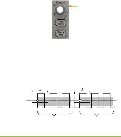
Force Trigger: Used to complete an acquisition regardless of an adequate trigger signal. This button becomes useless if the acquisition is already stopped.
Trigger Level
Holdoff: To use Trigger Holdoff, push the Trig Menu button and press Holdoff softkey. The Trigger Holdoff function can be used to generate a stable display of complex waveforms (such as pulse trains). Holdoff is the time between when the oscilloscope detects one trigger and when it is ready to detect another. During the holdoff time, the oscilloscope will not trigger. For a pulse train, the holdoff time can be adjusted to let the oscilloscope trigger only on the first pulse in the train.
Acquisition Interval |
Acquisition Interval |
Trigger Level
Indicates Trigger 

Points
Holdoff |
Holdoff |
Digital Storage Oscilloscope |
21 |
Loading...