


VC820/VC840 OPERATING MANUAL
Table of Contents
Title |
Page |
Overview
Unpacking Inspection
Safety Information
Rules For Safe Operation
Electrical Symbols
Functional Structure
Rotary Switch
Functional Buttons
Display Symbols
Manual Ranging and Autoranging
Measurement Operation
A.DC Voltage Measurement
B.AC Voltage Measurement
C.Measuring Resistance
D.Testing for Continuity
E.Testing Diode
F.Capacitance Measurement
G.Frequency or Duty Cycle Measurement
H.Temperature Measurement
I.DC or AC Current Measurement Operation of Hold Mode
The Use of Relative Value Mode POWER Button
1

VC820/VC840 OPERATING MANUAL
SELECT Button (blue)
General Specification
Accuracy Specification
A.DC Voltage
B.AC Voltage
C.Resistance
D.Continuity Test
E.Diode Test
F.Capacitance
G.Frequency & Duty Cycle
H.Temperature
I.DC Current
J.AC Current
Maintenance
A.General Maintenance & Service
B.Testing the Fuses
C.Replacing the Battery
D.Replacing the Fuses
RS232C Serial Port
A.Connect with computer
B.RS232C Port Cable
C.Setting of RS232C Serial Ports
D.System Requirements for Computer Interface Software
2

VC820/VC840 OPERATING MANUAL
Overview
This Operating Manual covers information on safety and cautions. Please read the relevant information carefully and observe all the warnings and notes strictly.
 Warning
Read the Rules for Safety Operation carefully before using the Meter
Digital Multimeter Model VC820 and VC840 (hereafter referred to as “the Meter”) has autorange and manual range options with maximum reading 3999. The enclosure structure design adopted advanced “co-injection” technique in order to provide sufficient insulation.
In addition to the conventional measuring functions, there is a RS232C standard serial port is equipped with this Meter for easy connection with computer to realize macro recording and monitoring and capture of transient dynamic data, displaying change of waveform during the measurement, providing data and evidence to engineering technicians for scientific research. This is also a highly applied digital multimeter of high performance with full input protection. VC840 also has true rms reading for AC voltage and AC current measurements.
Except where noted, the descriptions and instructions in this Operating Manual apply to both the VC820 and VC840.
Unpacking Inspection
Open the package case and take out the Meter. Check the following items carefully to see any missing or damaged part:
3

VC820/VC840 OPERATING MANUAL
|
Item |
Description |
Qty |
|
|
1 |
Operating Manual |
1 piece |
|
|
|
|
|
|
|
2 |
Test Lead |
1 pair |
|
|
|
|
|
|
|
3 |
RS232C (I) Interface cable |
1 piece |
|
|
|
|
|
|
|
4 |
Installation Guide & Software (CD-ROM) |
1 piece |
|
|
5 |
Test Clip |
1 piece |
|
|
|
|
|
|
|
6 |
Temperature Probe (VC840 ONLY) |
1 piece |
|
|
|
|
|
|
In the event you find any missing or damage, please contact your dealer immediately.
Safety Information
In this manual, a Warning identifies conditions and actions that pose hazards to the user, or may damage the Meter or the equipment under test.
This Meter complies with the standards GB4793.1 & IEC1010-1: In pollution degree 2, overvoltage category (CAT II 1000V, CAT III 600V) and double insulation.
CAT II: local classification of CAT II electronic equipment, portable units. Its transient overvoltage shall be less than that of CAT III.
CAT III: Distribution level, fixed installation, with smaller transient overvoltage than CAT IV
Rules For Safe Operation
4

VC820/VC840 OPERATING MANUAL
To avoid possible electric shock or personal injury, and to avoid possible damage to the Meter or to the equipment under test, adhere to the following rules:
1.Do not use this Meter in the event you find the test lead, LCD display, or insulation of the case is/are obviously broken, or you believe this Meter being malfunctioned.
2.If the test lead is/are damaged, replace new test lead with same model no. or identical electrical specifications.
3.When using the test leads, keep your fingers behind the finger guards.
4.Do not impose any effective voltage over 1000V on the terminal and earth of the Meter to prevent electric shock and damage to the Meter.
5.When the Meter working at an effective voltage over 60V in DC or 30V in AC, special care should be taken for there is danger of electric shock.
6.Do not operate the Meter with the case (or part of the case) removed; there is danger of electric shock.
7.When replacing fuse or battery, the test leads should be disconnected from the tested circuit and the POWER should be pressed off before opening the case.
8.Identical nominal fuse of quick response must be used for replacement of a broken fuse.
9.The rotary switch should be placed in the right position and no any changeover of range shall be made during measurement is conducted to prevent damage of the Meter.
10.The internal circuit of the Meter shall not be altered at will to avoid damage of the Meter and any accident.
11.Replace the battery as soon as the battery indicator 
 appears. With a low battery, the Meter might produce false readings that can lead to electric shock and personal injury.
12.Soft cloth and neutral detergent should be used to clean the surface of the Meter when servicing. No abrasive and solvent should be used to prevent the surface of the Meter from corrosion, damage and accident.
13.Do not use the Meter in an environment of high temperature, humidity, and storage of explosive or inflammable materials. Particularly not to put the Meter in a humid condition for storage. The performance of the Meter may deteriorate after dampened.
14.Use the proper terminals, function, and range for your measurements.
5

VC820/VC840 OPERATING MANUAL
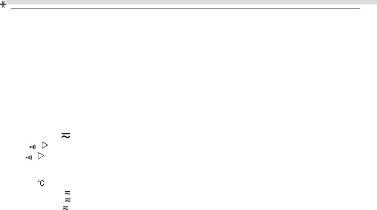
Electrical Symbols
AC (Alternating Current) |
Deficiency of Built-In Battery |
DC (Direct Current) |
Continuity Test |
AC or DC |
Diode |
Grounding |
Fuse |
Double Insulated |
Conforms to Standards of European Union |
Warning |
|
Functional Structure (see figure 1) 


LCD Display
6
VC820/VC840 OPERATING MANUAL
Functional Button
Rotary Switch
HzVΩ Input Terminal:
Insert the red test lead for testing voltage, frequency/duty cycle, resistance, diode, continuity and capacitance.
COM Terminal: Insert black test lead.
µAmA Input Terminal: (VC820 ONLY)
Insert red test lead for testing current µA or mA
or mA . µAmA0C Input Terminal: (VC840 ONLY)
Insert red test lead for testing current µA or mA
or mA or temperture.
20A Input Terminal:
Insert red test lead for testing current A
Rotary Switch
|
|
Switch Position |
Function |
|||
|
|
|
|
|
|
|
|
|
|
|
|
V |
AC or DC Voltage Measurement |
|
|
|
|
|
Ω (VC820 ONLY) |
Continuity or Diode or Resistance Test |
|
|
|
|
|
||
|
|
|
|
|
|
|
|
|
|
|
Ω (VC840 ONLY) |
Continuity or Diode or Resistance or Capacitance Test |
|
|
|
|
|
|||
|
|
|
|
|
||
|
|
|
|
(VC820 ONLY) |
Capacitance Test |
|
|
|
|
|
|
Hz |
Frequency Measurement |
|
|
|
(VC840 ONLY) |
Temperature in Celsius |
||
|
|
|
|
|
µA |
AC or DC Current Measurement from 0.1µA to 4000µA |
|
|
|
|
|
mA |
AC or DC Current Measurement from 0.01mA to 400.0mA |
|
|
|
|
|
A |
AC or DC Current Measurement from 0.001A to 20.00A |
7

VC820/VC840 OPERATING MANUAL
Functional Buttons
Button |
Function |
Operation Performed |
LCD Display |
POWER |
Power Switch |
Turn the power on and off. |
|
(the red button) |
|
|
|
|
|
|
|
SELECT |
Function Selector |
Press SELECT to select function when there is more |
|
(the blue button) |
|
than one function at one rotary switch position; the Meter |
|
|
|
beeps. |
|
|
|
|
|
RANGE |
Manual or Auto |
1. Press RANGE to enter the manual ranging mode; |
|
|
Range Selection |
the Meters beeps. |
|
|
|
Manually selecting a range causes the Meter to exit |
|
|
|
the Hold and REL modes. |
|
|
|
2. Press RANGE to step through the ranges available |
|
|
|
for the selected function; the Meter beeps. |
|
|
|
3. Press and hold RANGE for 2 seconds to return to |
|
|
|
autoranging; the Meter beeps. |
|
|
|
|
|
Hz % |
Frequency or Duty |
a. In frequency mode, press Hz % to toggle between |
Hz or % |
|
Cycle Test |
frequency measurement (Hz) and duty cycle (%) |
|
|
|
mode; the Meter beeps. |
|
|
|
b. In voltage or current mode, press Hz % to toggle |
|
|
|
V or µA or mA or |
|
|
|
between voltage (V) or current (A) measurement |
|
|
|
A or Hz or % |
|
|
|
and frequency measurement (Hz) and duty cycle (%) |
|
|
|
|
|
|
|
mode; the Meter beeps. |
|
|
|
|
|
8
VC820/VC840 OPERATING MANUAL
|
REL |
Relative |
Value |
Press REL to enter and exit the REL mode in any |
|
|
|
|
|
Mode |
|
mode; the Meter beeps. |
|
|
|
|
|
|
|
|
|
|
|
|
|
|
|
|
|
|
|
|
|
Data Holding |
|
Press HOLD to enter and exit the Hold mode in any |
|
|
|
|
HOLD H |
|
|
mode. |
|
|
|
|
|
|
|
|
|
||
|
|
|
|
|
|
|
|
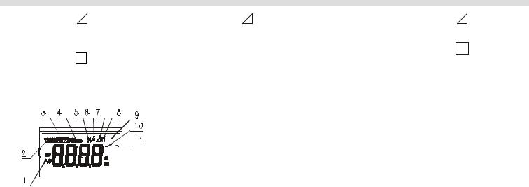
Display Symbols (see figure 2)
|
|
|
|
|
|
|
|
|
|
|
|
|
|
|
|
|
|
|
|
|
|
|
|
|
|
|
|
|
|
|
|
|
|
|
|
|
|
|
|
|
|
|
|
|
|
|
|
|
|
|
|
|
|
|
|
|
|
|
|
|
|
|
|
|
|
|
|
|
|
|
|
|
|
|
|
|
|
|
|
|
|
|
|
|
|
|
|
|
|
|
|
|
|
|
|
|
|
|
|
|
|
|
|
|
|
|
|
|
|
|
|
|
|
|
|
|
|
|
|
|
|
|
|
|
|
|
|
|
|
|
|
|
|
|
|
|
|
|
|
|
|
|
|
|
|
|
|
|
|
|
|
|
|
|
|
|
|
|
|
|
|
|
|
|
|
|
|
|
|
|
|
|
|
|
|
|
|
|
|
|
|
|
|
|
|
|
|
|
|
|
|
|
|
|
|
|
|
|
|
|
|
|
|
|
|
|
|
|
|
|
|
|
|
|
|
|
|
|
|
|
|
|
|
|
|
|
|
|
|
|
|
|
|
|
|
|
|
|
|
|
|
|
|
|
|
|
|
|
|
|
|
|
|
|
|
|
|
|
|
|
|
|
|
|
|
|
|
|
|
|
|
|
|
|
|
|
|
|
|
Number |
|
|
|
|
|
|
|
|
|
Symbol |
Meaning |
||||||||||||||||||
|
1 |
|
|
|
|
|
|
|
|
|
|
|
|
|
|
|
|
|
|
|
AC |
Indicator for AC voltage or current. |
||||||||
|
|
|
|
|
|
|
|
|
|
|
|
|
|
|
|
|
|
|
|
|
|
|
|
|
|
|
|
|
|
VC820: The displayed value is the mean value. |
|
|
|
|
|
|
|
|
|
|
|
|
|
|
|
|
|
|
|
|
|
|
|
|
|
|
|
TRMS |
VC840: The displayed value is the true rms value. |
||
|
2 |
|
|
|
|
|
|
|
|
|
|
|
|
|
|
|
|
|
|
|
Indicator for true rms value. |
|||||||||
|
|
|
|
|
|
|
|
|
|
|
|
|
|
|
|
|
|
|
|
|
(VC840ONLY) |
|
||||||||
9

VC820/VC840 OPERATING MANUAL
|
3 |
|
|
|
|
|
|
The Meter is in the auto range mode in which the Meter automatically selects the |
|
|
|
|
|
|
|
|
|
|
range with the best resolution. |
|
|
|
4 |
RS232C |
Data output is in progress. |
|
||||||
|
|
|
|
|
|
|
|
|
|
|
|
5 |
% |
|
|
Indicator for duty cycle. |
|
||||
|
6 |
|
|
|
|
|
|
Data hold is active. |
|
|
|
|
|
|
|
|
|
|
|||
|
|
|
|
|
|
|
|
|
|
|
|
7 |
|
|
|
|
|
|
The relative value mode is on to display the stored value minus the present value. |
|
|
|
|
|
|
|
|
|
|
|
|
|
|
8 |
|
|
|
|
|
|
The battery is low. |
|
|
|
|
|
|
|
|
|
|
Warning: To avoid false readings, which could lead to possible electric |
|
|
|
|
|
|
|
|
|
|
shock or personal injury, replace the battery as soon as the battery indicator |
|
|
|
|
|
|
|
|
|
|
appears. |
|
|
|
9 |
|
|
0C |
Centigrade. The unit of temperature. |
|
||||
|
10 |
|
|
|
|
|
|
Test of diode |
|
|
|
|
|
|
|
|
|
|
|
||
|
|
|
|
|
|
|
|
|
|
|
|
11 |
|
|
|
|
|
|
The continuity buzzer is on. |
|
|
|
12~16 |
Ω,kΩ,MΩ |
Ω: |
Ohm. The unit of resistance. |
|
|||||
|
|
|
|
|
|
|
|
kΩ: |
kilohm. 1 x 10³ or 1000 ohms. |
|
|
|
|
|
|
|
|
|
MΩ: |
Megohm. 1 x 10⁶ or 1,000,000 ohms. |
|
|
|
|
|
|
|
|||||
|
|
µF, nF |
F: |
Farad. The unit of capacitance. |
|
|||||
|
|
|
|
|
|
|
|
µF: |
Microfarad. 1 x 10⁻⁶ or 0.000001 farads. |
|
|
|
|
|
|
|
|
|
nF: |
Nanofarad. 1 x 10⁻⁹ or 0.000000001 farads. |
|
|
|
|
|
|
|
|||||
|
|
Hz, kHz, MHz |
Hz: |
Hertz. The unit of frequency. |
|
|||||
|
|
|
|
|
|
|
|
kHz: |
Kilohertz. 1 x 10³ or 1000 hertz. |
|
|
|
|
|
|
|
|
|
MHz: |
Meghertz. 1 x 10⁶ or1,000,000 hertz. |
|
|
|
|
|
|
|
|
|
|
|
|
10
VC820/VC840 OPERATING MANUAL
|
|
V, mV |
V: |
Volts. The unit of voltage. |
|
|
|
|
mV |
Millivolt. 1 x 10⁻³ or 0.001 volts. |
|
|
|
|
|
|
|
|
|
A, mA, µA |
A: |
Amperes (amps). The unit of current. |
|
|
|
|
mA: |
Milliamp. 1 x 10⁻³ or 0.001 amperes. |
|
|
|
|
µA: |
Microamp. 1x 10⁻⁶ or 0.000001 amperes. |
|
|
17 |
|
Indicates negative reading. |
|
|
|
|
|
|
|
|
|
18 |
OL |
The input value is too large for the selected range. |
|
|
Manual Ranging and Autoranging
The Meter has both manual range and autorange options:
zIn the autorange ( ) mode, the Meter selects the best range for input signals. This allows you to switch test points without having to reset the range.
zIn the manual range mode, you may select the range.
This allows you to override autorange and lock the Meter in a specific range.
The Meter defaults to the autorange mode in measurement functions that have more than one range. When the Meter is in the autorange mode,  is displayed.
To enter and exit the manual range mode:
1.Press RANGE.
The Meter enters the manual range mode and  turns off
11

VC820/VC840 OPERATING MANUAL
Each presses of RANGE increments the range. When the highest range is reached, The Meter wraps to the lowest range.
NOTE
If you manually change the measurement range after entering the REL or Hold recording modes, the Meter exits these modes..
2.To exit the manual range model, press and hold RANGE for two seconds. The Meter returns to the autorange mode and  is displayed.
Measurement Operation
A. DC Voltage Measurement
 Warning
To avoid harms to you or damages to the Meter from electric shock, please do not attempt to measure voltages higher than 1000V / 750V TRMS although readings may be obtained.
The DC Voltage ranges are: 400.0mV, 4.000V, 40.00V, 400.0V and 1000V. To measure DC Voltage, connect the Meter as follows:
1.Insert the red test lead into the HzVΩ terminal and the black test lead into the COM terminal.
2.Set the rotary switch to V (DC measurement is default)
3.Connect the test leads across with the object being measured.
12

VC820/VC840 OPERATING MANUAL
The measured value shows on the display.
In each range, the Meter has an input impedance of 10MΩ. This loading effect can cause measurement errors in high impedance circuits. If the circuit impedance is less than or equal to 10kΩ, the error is negligible (0.1% or less).
When DC voltage measurement has been completed, disconnect the connection between the testing leads and the circuit under test, and remove the testing leads away from the input terminals of the Meter.
B. AC Voltage Measurement
 Warning
To avoid harms to you or damages to the Meter from electric shock, please do not attempt to measure voltages higher than 1000V / 750V TRMS although readings may be obtained.
The AC Voltage ranges are: 400.0mV, 4.000V, 40.00V, 400.0V and 750V. To measure AC Voltage, connect the Meter as follows:
1.Insert the red test lead into the HzVΩterminal and the black test lead into the COM terminal.
2.Set the rotary switch to V and press SELECT (blue button) to select AC measurement.
3.Connect the test leads across with the object being measured. The measured value shows on the display.
In each range, the Meter has an input impedance of 10MΩ. This loading effect can cause measurement errors in high impedance circuits. If the circuit impedance is less than or equal to 10kΩ, the error is negligible (0.1% or less).
Effective value stability period:
13
 Loading...