


 Loading...
VOLTCRAFT DSO4084B, DSO4104B, DSO4204B, DSO4254B, DSO4084C User guide
...DSO4000B(C) Series
Digital Storage Oscilloscope
User Manual
Version 1.0
Digital Storage Oscilloscope |
I |

Copyright Declaration
All rights reserved; no part of this document may be reproduced or transmitted in any form or by any means, electronic or mechanical, without prior written permission from Hantek Technologies Co., Ltd (hereinafter referred to as ‘Hantek’).
Hantek reserves all rights to modify this document without prior notice. Please contact Hantek for the latest version of this document before placing an order.
Hantek has made every effort to ensure the accuracy of this document but does not guarantee the absence of errors. Moreover, Hantek assumes no responsibility in obtaining permission and authorization of any third party patent, copyright or product involved in relation to the use of this document.
Digital Storage Oscilloscope |
II |

General Safety Summary
Read the following safety precautions to avoid injury and prevent damage to this product or any products connected to it. To evade potential hazards, use this product only as specified.
Only qualified personnel should perform maintenance.
Avoid fire or personal injury.
Use suitable power cord. Use only the power cord specified for this product and certified for the country of use.
Connect and disconnect properly. Connect a probe with the oscilloscope before it is connected to measured circuits; disconnect the probe from the oscilloscope after it is disconnected from measured circuits.
Ground the product. This product is grounded through the grounding conductor of the power cord. To avoid electric shock, the grounding conductor must be connected to earth ground. Before making connections to the input or output terminals of the product, ensure that the product is properly grounded.
Connect the probe in a right way. The probe ground lead is at ground potential. Do not connect the ground lead to an elevated voltage.
Check all terminal ratings. To avoid fire or shock hazard, check all ratings and markings on the product. Refer to the product manual for detailed information about ratings before making connections to the product.
Do not operate without covers. Do not operate this product with covers or panels removed.
Avoid exposed circuitry. Do not touch exposed connections and components when power is present.
Do not operate with suspected failures. If you suspect there is damage to this product, have it inspected by qualified service personnel.
Assure good ventilation.
Do not operate in wet/damp environments.
Do not operate in an explosive atmosphere.
Keep product surfaces clean and dry.
Digital Storage Oscilloscope |
III |
Safety Terms and Symbols
Terms on the product. The following terms may appear on the product:
Danger It represents that harms may be caused to you at once if you perform the operation.
Warning It represents that latent harms may be caused to you if you perform the operation.
Notice It represents the damage possibly caused to the product or other properties if you perform the operation.
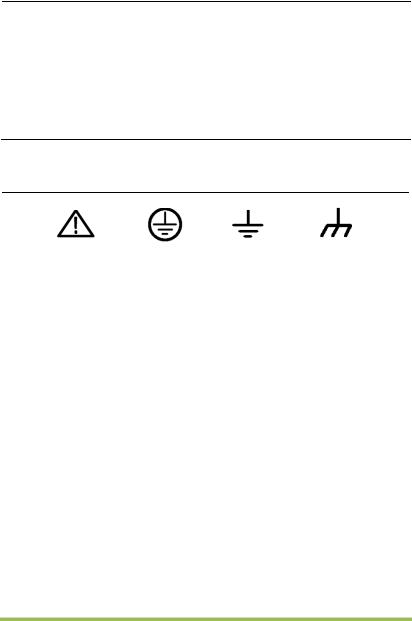
Characters on the product. The following characters may appear on the product:
Notice |
Protective |
Measuring |
Chassis |
|
|||
Please read |
ground terminal |
ground terminal |
ground terminal |
|
|||
the manual |
|
|
|
|
|
|
|
Product Scrapping
Device Recycling
We need extract and utilize natural resources to produce this device. If you do not reclaim the device in a proper way, some substances it contains may become harmful or poisonous to environments or human bodies. To avoid them being released outside and to minimize the waste of natural resources, we suggest you reasonably call back this device to ensure proper recovery and recycling of most materials within it.
Digital Storage Oscilloscope |
IV |

Brief Introduction to the Series of digital
storage oscilloscope
DSO4000B(C) Series oscilloscopes cover the bandwidths from 80MHz to 200MHz, and provide the real-time up to 1GSa/s. In addition, they have 7 inch color TFT LCD as well as WINDOWS-style interfaces and menus for easy operation.
What’s more, the plenty menu information and the easy-to-operate buttons allow you to gain information as much as possible in measurement; the multifunctional knobs and the powerful shortcut keys help you save a lot of time in operation; the Autoset function lets you detect sine and square waves automatically; the Probe Check Wizard guides you to adjust the probe compensation and set the Probe option attenuation factor. By using the three methods the oscilloscope provides (context-sensitive, hyperlinks, and an index), you may master all operations on the device in quite a short time so as to greatly improve your efficiency in production and development.
Model |
Channels |
Bandwidth |
Sample Rate |
AFG |
|
|
|
|
|
DSO4084B |
4 |
80MHz |
1GS/s |
- |
|
|
|
|
|
DSO4104B |
4 |
100MHz |
1GS/s |
- |
|
|
|
|
|
DSO4204B |
4 |
200MHz |
1GS/s |
- |
|
|
|
|
|
DSO4254B |
4 |
250MHz |
1GS/s |
- |
|
|
|
|
|
DSO4084C |
4 |
80MHz |
1GS/s |
Yes |
|
|
|
|
|
DSO4104C |
4 |
100MHz |
1GS/s |
Yes |
|
|
|
|
|
DSO4204C |
4 |
200MHz |
1GS/s |
Yes |
|
|
|
|
|
DSO4254C |
4 |
250MHz |
1GS/s |
Yes |
|
|
|
|
|
Digital Storage Oscilloscope |
IV |

|
Contents |
|
Copyright Declaration............................................................................................... |
II |
|
General Safety Summary ...................................................................................... |
III |
|
Safety Terms and Symbols ................................................................................... |
IV |
|
Product Scrapping................................................................................................ |
IV |
|
Brief Introduction to the Series of digital storage oscilloscope............................... |
IV |
|
Contents ................................................................................................................... |
|
V |
Chapter 1 |
Introduction........................................................................................ |
1 |
1.1 |
General Inspection ................................................................................... |
2 |
1.2 |
Prepare Instrument for Use....................................................................... |
3 |
1.3 |
Accidence of front panel and the user interface ........................................ |
1 |
1.3.1 |
User Interface ...................................................................................... |
1 |
1.4 |
Functional Check...................................................................................... |
3 |
1.4.1 |
Connect the oscilloscope ..................................................................... |
3 |
1.4.2 |
Observe the waveform ......................................................................... |
3 |
1.5 |
Probe Introduction .................................................................................... |
4 |
1.5.1 |
Safety .................................................................................................. |
4 |
1.5.2 |
Use of Probe Check Wizard ................................................................. |
4 |
1.5.3 |
Manual Probe Compensation............................................................... |
4 |
1.5.4 |
Probe Attenuation Setting..................................................................... |
5 |
Chapter 2 |
Function Introduction ........................................................................ |
7 |
2.1 |
Menu and control keys.............................................................................. |
8 |
2.2 |
Connector................................................................................................. |
9 |
2.3 |
Default setups........................................................................................... |
9 |
2.4 |
Multi-functional Knobs and Buttons......................................................... |
10 |
2.5 |
Oscilloscope Setup................................................................................. |
10 |
2.6 |
Horizontal Controls ................................................................................. |
11 |
2.6.1 |
Scan Mode Display (Roll Mode) ......................................................... |
12 |
2.7 |
Vertical System....................................................................................... |
12 |
|
Digital Storage Oscilloscope |
V |
2.7.1 |
|
Vertical Controls................................................................................. |
12 |
|
2.7.2 |
|
Math FFT ........................................................................................... |
|
15 |
2.8 |
Trigger System ....................................................................................... |
|
20 |
|
2.8.1 |
|
Trigger Controls ................................................................................. |
21 |
|
2.8.2 |
|
Holdoff ............................................................................................... |
|
40 |
2.9 |
SAVE/RECALL ....................................................................................... |
|
40 |
|
2.10 |
MEASURE System ................................................................................. |
42 |
||
2.10.1 |
Scale measurement....................................................................... |
42 |
||
2.10.2 |
Cursor measurement..................................................................... |
43 |
||
2.10.3 |
Automatic Measurement................................................................ |
44 |
||
2.11 |
ACQUIRE ............................................................................................... |
|
47 |
|
2.12 |
DISPLAY ................................................................................................ |
|
51 |
|
2.12.1 |
XY Format ..................................................................................... |
51 |
||
2.13 |
UTILITY System ..................................................................................... |
52 |
||
2.13.1 |
Firmware51B |
Update........................................................................... |
52 |
|
2.13.2 |
Self52B Calibration .............................................................................. |
53 |
||
2.13.3 |
Pass/fail56B ........................................................................................ |
|
53 |
|
2.14 |
Fast Action Buttons................................................................................. |
55 |
||
2.14.1 |
AUTOSET ..................................................................................... |
55 |
||
2.14.2 |
Default Setup ................................................................................ |
57 |
||
Chapter 3 |
|
Waveform Generator........................................................................ |
60 |
|
Chapter 4 |
|
Troubleshooting............................................................................... |
62 |
|
4.1 |
Problem Settlement ................................................................................ |
62 |
||
Chapter 5 |
|
Services and Support ...................................................................... |
90 |
|
Chapter 6 |
|
General Care and Cleaning ............................................................. |
91 |
|
6.1 |
General Care .......................................................................................... |
|
91 |
|
6.2 |
Cleaning ................................................................................................. |
|
91 |
|
Appendix A: Technical Specifications ................................................................... |
92 |
|||
Appendix B: Accessories ....................................................................................... |
|
99 |
||
|
|
|
|
|
|
|
|
Digital Storage Oscilloscope |
VI |

Appendix C Harmful and Poisonous Substances or Elements .......................... |
100 |
Digital Storage Oscilloscope |
VII |
Chapter 1 Introduction
General Inspection
Prepare Instrument for Use
Accidence of front panel and the user interface
Functional Check
Probe Introduction
1.1 General Inspection
Please check the instrument as following steps after receiving an oscilloscope:
Check the shipping container for damage:
Keep the damaged shipping container or cushioning material until the contents of the shipment have been checked for completeness and the instrument has been checked mechanically and electrically.
Check the accessories:
Accessories supplied with the instrument are listed in "Accessories" in this guide. If the contents are incomplete or damaged, please notify the franchiser.
Check the instrument:
In case there is any mechanical damage or defect, or the instrument does not operate properly or fails performance tests, please notify the franchiser.
1.2 Prepare Instrument for Use
Adjust the Supporting Legs
Adjust the supporting legs properly to use them as stands to tilt the oscilloscope upwards for stable placement of the oscilloscope as well as better operation and observation.
Connect the Power Cord
Connect the power cord as desired. Turn the instrument on by pressing the power switch in the lower left corner of front panel.
If the instrument does not turn on, verify that the power cord is firmly connected (power-line voltage is automatically sensed at power-on). Also make sure that the instrument is connected to an energized power source.
Power Switch:
To turn off the instrument, please press power switch.

1.3 Accidence of front panel and the user
interface
This section will make you understand the front operation panel of this series of digital oscilloscope at first before use.
1.3.1User Interface
Figure 1-2 Interface display
1.Hantek logo
2.Trigger Status:
Auto: The oscilloscope works in auto mode and is acquiring waveforms in the absence of triggers.
Ready: All pre-triggered data have been acquired and the oscilloscope is ready to accept a trigger.
Roll: The oscilloscope is acquiring and displaying waveform data continuously in roll mode.
Stop: The oscilloscope has stopped acquiring waveform data.
Digital Storage Oscilloscope |
1 |

3.Readout shows main time base setting.
4.Sample rate.
5.Main Time Base Window
6.Tigger time
7.Trigger level, Readout tells trigger level
8.Operating Menu shows different information for respective function keys.
9.If this icon lights up/active, it means the USB disk has been connected.
10.If this icon lights up/active, it means the wave generator works
11.The information of coupling, Bandwidth and volt/div of CH1~CH4.
12.Channel Marker
13.Window displays waveform.
Digital Storage Oscilloscope |
2 |
1.4 Functional Check
Follow the steps below to perform a quick functional check to your oscilloscope.
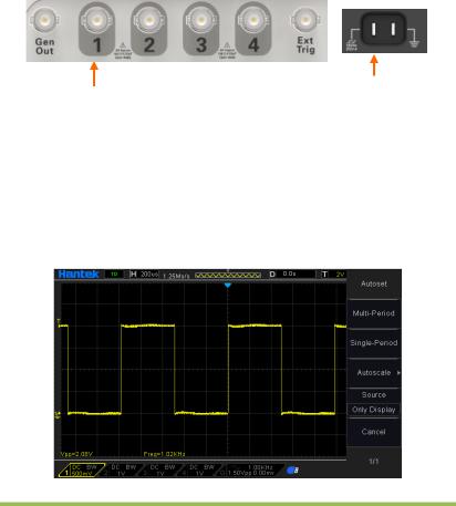
1.4.1Connect the oscilloscope
Set the switch on the probe to 10X and connect the probe to Channel 1 on the oscilloscope. First, align the slot in the probe connector with the protuberance on the CH1 BNC and push to connect; then, turn to right to lock the probe in place; after that, connect the probe tip and reference lead to the PROBE COMP connectors. There is a mark on the panel: Probe COMP ~2V@1KHz.
CH1: to connect with the probe |
PROBE COMP |
|
1.4.2Observe the waveform
Press the AUTOSET button and you should see within a few seconds a square wave of about 2V peak-to-peak at 1KHz in the display. Press the CH1 MENU button twice to remove Channel 1. Push the CH2 MENU button and repeat Step 2 and Step 3 to observe CH2, CH3 and CH4.
Digital Storage Oscilloscope |
3 |

1.5 Probe Introduction
1.5.1Safety
When using the probe, keep your fingers behind the guard on the probe body to avoid electric shock. Do not touch metallic portions of the probe head while it is connected to a voltage source. Connect the probe to the oscilloscope and connect the ground terminal to ground before you start any measurements.
1.5.2Use of Probe Check Wizard
Every time you connect a probe to an input channel, you should use the probe check wizard to verify that this probe is operating correctly. There are two ways to do this: Use the vertical menu (for example, push the CH1 MENU button) to set the Probe option attenuation factor.
Press the PROBE CHECK button to use the Probe Check Wizard and configure the probe option attenuation factor properly following menu prompts.
1.5.3Manual Probe Compensation
Upon the first connection of a probe and an input channel, you should manually perform this adjustment to match the probe to the input channel. Uncompensated or miscompensated probes may lead to errors or faults in measurement. To adjust the probe compensation, follow the steps below.
1.Set the Probe option attenuation in the channel menu to 10X. Set the switch on the probe to 10X and connect the probe to Channel 1 on the oscilloscope. If you use the probe hook-tip, ensure it is firmly inserted onto the probe. Attach the probe tip to the PROBE COMP ~2V@1KHz connector and the reference lead to
Digital Storage Oscilloscope |
4 |
the PROBE COMP Ground connector. Display the channel and then press the AUTOSET button.
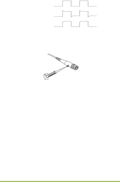
2. Check the shape of the displayed waveform.
Compensated correctly
Overcompensated
Undercompensated
3.If necessary, use a nonmetallic screwdriver to adjust the variable capacity of your probe until the shape of the waveform turns to be the same as the above figure. Repeat this step as necessary. See the figure below for the way of adjustment.
1.5.4Probe Attenuation Setting
Probes are of various attenuation factors which affect the vertical scale of the signal. The Probe Check function is used to verify if the Probe attenuation option matches the attenuation of the probe.
As an alternative method to Probe Check, you can push a vertical menu button (such as the CH 1 MENU button) and select the Probe option that matches the attenuation factor of your probe.
Make sure that the Attenuation switch on the probe matches the Probe option in the oscilloscope. Switch settings are 1X and 10X.
When the Attenuation switch is set to 1X, the probe limits the bandwidth of the oscilloscope to 6MHz. To use the full bandwidth of the oscilloscope, be sure to set the
Digital Storage Oscilloscope |
5 |

switch to 10X.
Digital Storage Oscilloscope |
6 |

Chapter 2 Function Introduction
This chapter provides some general information that you need to learn before using an
oscilloscope. It contains:
Menu and control keys
Connector
Default setups
Multi-functional Knobs and Buttons
Oscilloscope Setup
Horizontal Controls
Vertical System
Trigger System
SAVE/RECALL
MEASURE System
ACQUIRE
DISPLAY
UTILITY System
Fast Action Buttons
Digital Storage Oscilloscope |
7 |
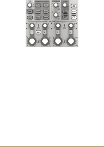
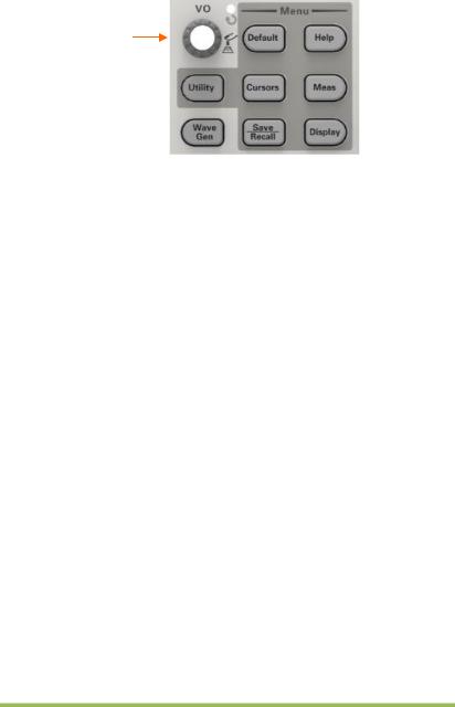
2.1 Menu and control keys
As shown in the figure below:
Figure 2-1 Control keys
All the keys are described as follows:
[CH1], [CH2], [CH3], [CH4]: display setup menus of channel 1 and channel 2.
[Math]: display “Arithmetical operation” waveform menu.
[Horizontal]: display “HORIZONTAL” menu.
[Trig Menu]: display “TRIGGER” control menu.
[Force Trig]: It is used for finishing acquisition of the current waveform no matter whether the oscilloscope detects trigger, and it is mainly applied to “NORMAL” and “SINGLE” in the trigger mode.
[Default]: recall the default factory setup.
[Help]: enter the on-line help system.
[Utility]: display “UTILITY FUNCTION” menu.
[Cursors]: display the “CURSOR” menu. The [V0] knob can be used for regulating the position of the cursor when the “CURSOR” menu is displayed and the cursor is triggered.
[Meas]: show the “Measure” menu.
[Wave Gen]: show the waveform generator menu.
[Save Recall]: show the “Save/Recall” menu of setups and waveform..
[Display]: show the “Display” menu.
[Auto Scale]: automatically set the control state of the oscilloscope so as to display suitable waveform.
Digital Storage Oscilloscope |
8 |

[Run/STtop]: continuously acquire waveform or stop acquisition
[Single]: Acquire a single trigger, finish acquisition and then stop.
2.2 Connector
Figure 2-2 Connector
CH1, CH2, CH3, CH4: for an input connector of a measured signal.
EXT TRIG: be used as an input connector of an external trigger source. Use [TRIG MENU] to select “EXT” trigger source, and the trigger signal source can be used for triggering in the third channel while acquiring data in two channels.
Gen Out: Waveform signal output.
Probe compensation: The probe compensation signal is output and grounded so that the probe is matched with the channels of the oscilloscope.
2.3 Default setups
The [DEFAULT] key represents the default setup function, most of the options and control setups of the factory are recalled by pressing them, some setups are not changed, and the following setups are not reset:
Language Option
Saved Reference Waveforms
Saved Settings
Display Contrast
Calibration Data
Digital Storage Oscilloscope |
9 |
2.4 Multi-functional Knobs and Buttons
V0: Multi-functional knob. Under different menu options, it supports selecting menu options (MEASURE), moving cursors and levels (Slope Trigger).
Press this knob to reset data (trigger holdoff, overtime of the overtime trigger
and slope trigger), select menu options and so on. Easy to operate.
F7: Push this button in single-window mode to switch between dotted line
F0: Hide/Show button. Push it to hide the menu options on the right side of the screen and give a full screen display of waveforms. Push it again to show the menu options.
F1-F5: These five buttons are all multi-functional. They are in charge of selecting corresponding menu options on the screen in different menu modes. For example, in the UTILITY menu, F1-F5 respectively correspond to
‘System Info’ – ‘Advance’.
F6: This functional button is mainly used to turn pages and confirm a selection, such as ‘next page’, ‘previous page’, and ‘press F6 to confirm’ appearing when you push Self Calibration option.
2.5 Oscilloscope Setup
While operating the oscilloscope, you may often use three features: Autoset, saving a setup and recalling a setup. Hereinafter they are introduced one by one.
Autoset: This function can be used to adjust the horizontal and vertical scales of the
Digital Storage Oscilloscope |
10 |
oscilloscope automatically and set the trigger coupling, type, position, slope, level and mode, etc., to acquire a stable waveform display.
Saving a Setup: By default, the oscilloscope will save the setup each time before being closed, and automatically recall the setup once being turned on. (Note: If you modify the setup, please wait for more than 5 seconds before turning off the oscilloscope to ensure the proper storage of new settings.) You can save 10 settings permanently in the oscilloscope and reset them as necessary.
Recalling a Setup: The oscilloscope can recall any of your saved setups or the default
factory setup.
Default Setup: The oscilloscope is preset for normal operations when it is shipped from the factory. This is the default setup. You may recall this setup at any time for your requirements.
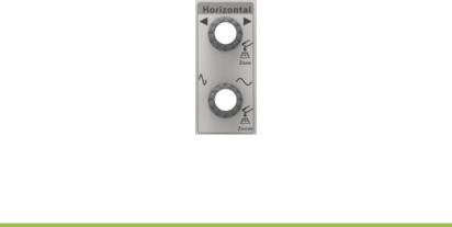
2.6 Horizontal Controls
Use the horizontal controls to change the horizontal scale and position of waveforms. The horizontal position readout shows the time represented by the center of the screen, using the trigger time as zero. When you change the horizontal scale, the waveform will expand or contract to the screen center. The readout near the upper right of the screen shows the current horizontal position in second. M represents ‘Main Time Base’, and W indicates ‘Window Time Base’. The oscilloscope also has an arrow icon at the top of the graticule to indicate the horizontal position.
1. Horizontal Position Knob: Used to control the trigger position against the screen center. Push this button to reset the trigger point back to the screen center.
AN: Used to set the horizontal position as zero.
Digital Storage Oscilloscope |
11 |
Multi-functional
Knob
2.SEC/DIV Knob: Used to change the horizontal time scale so as to magnify or compress the waveform horizontally. If the waveform acquisition is stopped (by using the RUN/STOP or SINGLE SEQ button), the SEC/DIV control will expand or compress the waveform. In dual-window mode, push this knob to select major or minor window. When the major window is selected, this knob provides the same functions as it provides in single-mode window. When the minor window is selected, turn this knob to scale the waveform whose magnification is up to 1000.
Notes:
1.For more information of the trigger holdoff, see Section Trigger Controls.
2.6.1Scan Mode Display (Roll Mode)
With the SEC/DIV control set to 80ms/div or slower and the trigger mode set to Auto, the oscilloscope works in the scan acquisition mode. In this mode, the waveform display is updated from left to right without any trigger or horizontal position control.
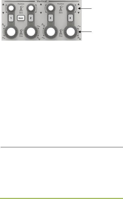
2.7 Vertical System
2.7.1Vertical Controls
Vertical controls can be used to display and remove waveforms, adjust vertical scale and position, set input parameters and perform math calculations. Each channel has a separate vertical menu to set. See below for menu description.
Digital Storage Oscilloscope |
12 |
Position
Volt/div
1.Vertical Position Knob: Move the channel waveform up and down on the screen. In dual-window mode, move the waveforms in both windows at the same time in a same direction. Push this knob to return waveforms to the vertical center position on the screen. Two channels correspond to two knobs.
2.VOLTS/DIV Knob
Control the oscilloscope to magnify or attenuate the source signal of the channel waveform. The vertical size of the display on the screen will change (increase or decrease) to the ground level. Also you may use this knob to switch between coarse and fine.
3.Menu (CH1, CH2, Ch3, CH4): Display vertical menu options; turn on or off the display of channel waveforms.
Options |
Settings |
Comments |
|
|
|
DC Coupling AC
GND
DC passes both DC and AC components of the input signal.
AC blocks the DC component of the input signal and attenuates signals below 10Hz.
Ground disconnects the input signal.
20MHz |
Limit Off |
Limits the bandwidth to reduce display noise; filters |
|
Bandwidth |
the signal to eliminate noise and other unnecessary |
||
Limit On |
|||
Limit |
HF components. |
||
|
|||
|
|
|
|
|
|
Selects the resolution of the VOLTS/DIV knob. |
|
DIV |
Coarse |
Coarse defines a 1-2-5 sequence. Fine changes the |
|
Fine |
resolution to small steps between the Coarse |
||
|
|||
|
|
settings. |
|
|
|
|
Digital Storage Oscilloscope |
13 |
|
1X |
Selects a value according to the probe attenuation |
|
Probe |
10X |
||
factor so as to ensure correct vertical readouts. |
|||
Attenuation |
100X |
||
Reduce bandwidth to 6MHz when using a 1X probe. |
|||
|
1000X |
||
|
|
||
|
|
|
|
Invert |
Off |
Inverts the waveform relative to the reference level. |
|
On |
|||
|
|
||
|
|
|
Coupling
If the channel adopts a DC coupling mode, you can quickly measure the DC component of the signal by observing the difference between the waveform and the signal ground.
If the channel adopts an AC coupling mode, the DC component in the signal is filtered. By this mode, the AC component of the signal is displayed at a higher sensitivity.
If the channel adopts a GND coupling mode, cut off the input signal. Inside the channel, the channel input is connected with a zero volt reference electric level.
Fine Resolution
In the fine resolution setting, the vertical scale readout displays the actual VOLTS/DIV setting. The vertical scale changes only after you adjust the VOLTS/DIV control and set to coarse.
Remove Waveform Display
To remove a waveform from the screen, first push the menu button to display the vertical menu, then push again to remove the waveform. A channel waveform which is unnecessary to be displayed can be used as a trigger source or for math operations.
4.MATH MENU: Display the waveform math operations. See the table below for details.
The MATH menu contains source options for all math operations.
|
Operations |
|
Source |
|
Comments |
|
|
|
Options |
|
|
||
|
|
|
|
|
|
|
|
|
|
|
|
|
|
Operator |
+, -, *, /, FFT |
|
||||
|
|
|
|
|
|
|
|
|
|
|
|
Five types of window available for selection: |
|
|
|
|
CH1, CH2 |
|
||
FFT |
|
|
Hanning, Flattop, Rectangular,Bartletta |
and |
||
|
|
|
CH3, CH4 |
|
||
|
|
|
|
|
Blackman |
|
|
|
|
|
|
|
|
|
|
|
|
|
|
|
|
|
|
|
|
Digital Storage Oscilloscope |
14 |

Zoom: Use the FFT Zoom button to adjust the window size.
Scale: x1, x2, x5, x10.
Note: All selected menus are highlighted in orange.
2.7.2Math FFT
This chapter elaborates how to use the Math FFT (Fast Fourier Transform). You can use the Math FFT mode to convert a time-domain (YT) signal into its frequency components (spectrum), and to observe the following types of signals:
Analyze harmonics in power cords;
Measure harmonic content and distortion in systems;
Characterize noise in DC power supplies;
Test impulse response of filters and systems;
Analyze vibration.
To use the Math FFT mode, perform the following tasks:
Set the source (time-domain) waveform;
Display the FFT spectrum;
Choose a type of FFT window;
Adjust the sample rate to display the fundamental frequency and harmonics without aliasing;
Use zoom controls to magnify the spectrum;
Use cursors to measure the spectrum.
2.7.2.1 Setting Time-domain Waveform
It is necessary to set the time-domain (YT) waveform before using the FFT mode.
Follow the steps below.
1.Push the AUTOSET button to display a YT waveform.
2.Turn the VERTICAL POSITION knob to vertically move the YT waveform to the center (zero division) so as to ensure the FFT will display a true DC value.
3.Turn the HORIZONTAL POSITION knob to position the part of the YT waveform to be analyzed in the center eight divisions of the screen. The oscilloscope uses the 2048 center points of the time-domain waveform to calculate the FFT spectrum.
Digital Storage Oscilloscope |
15 |
Loading...