


LIGHTING – LIGHTING SYSTEM |
LI–1 |
|
LIGHTING SYSTEM
PRECAUTION
1.PRECAUTION FOR USING BATTERY DURING INSPECTION
(a)While using the battery during inspection, do not bring the positive and negative tester probes too close to each other as a short circuit may occur.
2.PRECAUTION FOR HEADLIGHT BULB REPLACEMENT
(a)If even a thin film of oil is left on the surface of the halogen light, the bulb may be damaged because the light will burn at a higher temperature.
(b)Handle any halogen light with great care. Dropping, hitting or damaging the bulb, in any way, may result in exploding and shattering because the internal pressure is high.
(c)Always prepare a new bulb for immediate replacement. While replacing the bulb, the lens may attract dust and moisture if removed from the vehicle for too long.
(d)Always use a bulb of the same wattage for replacement.
(e)Firmly reinstall the socket after bulb replacement. The lens may become cloudy or the light cavity may fill with water through the gaps around the socket.
3.EXPRESSIONS OF IGNITION SWITCH
(a)The type of ignition switch used on this model differs according to the specifications of the vehicle.
The expressions listed in the table below are used in this section.
Switch Type |
Ignition Switch (position) |
Engine Switch (condition) |
|
|
|
|
|
|
|
|
|
|
Ignition switch off |
LOCK |
Off |
|
|
|
|
|
|
|
|
Expression |
Ignition switch on (IG) |
ON |
On (IG) |
|
|
|
|
|
|
|
|
Ignition switch on (ACC) |
ACC |
On (ACC) |
|
|
|
|
|
|
|||
|
|
|
|
|
|
|
Engine start |
START |
Start |
|
LI |
|
|
|
|||
|
|
|
|
|
|
|
|
|
|
|
|
LI–2 |
LIGHTING – LIGHTING SYSTEM |
|
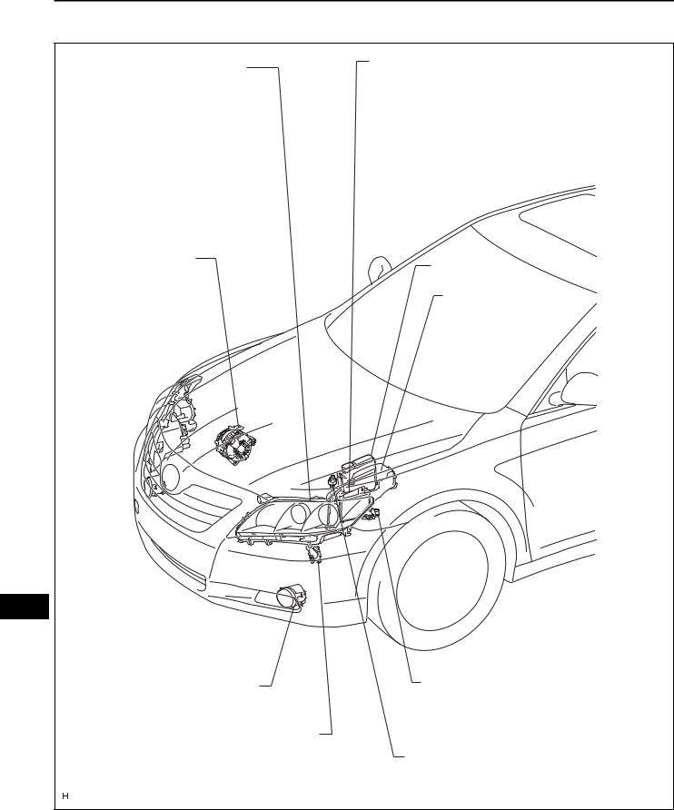
PARTS LOCATION
HEADLIGHT ASSEMBLY
-LOW BEAM HEADLIGHT
-HIGH BEAM HEADLIGHT
-FRONT SIDE MARKER LIGHT
-TURN SIGNAL AND PARKING LIGHT
GENERATOR
LI
FOG LIGHT ASSEMBLY
PARK / NEUTRAL POSITION SWITCH (FOR U250E A/T)
ENGINE ROOM J/B ASSEMBLY
-POWER DISTRIBUTOR
-H-LP (LL) FUSE
-H-LR (RL) FUSE
-H-LP (LH) FUSE
-H-LP (RH) FUSE
ECM
ENGINE ROOM R/B
-DOME FUSE
-HAZ FUSE
PARK / NEUTRAL POSITION SWITCH (FOR U660E A/T)
BACK-UP LIGHT SWITCH (FOR M/T)
E121472E01

LIGHTING – LIGHTING SYSTEM |
LI–3 |
|
WITHOUT SLIDING ROOF:
PERSONAL LIGHT ASSEMBLY (OVERHEAD J/B)
-FRONT PERSONAL LIGHTS
-INTERIOR LIGHT
VANITY LIGHT
PERSONAL LIGHT ASSEMBLY (OVERHEAD J/B)
- FRONT PERSONAL LIGHTS
REAR ROOM LIGHT ASSEMBLY - INTERIOR LIGHT
VANITY LIGHT
REAR ROOM LIGHT ASSEMBLY - REAR PERSONAL LIGHTS
REAR COMBINATION LIGHT ASSEMBLY
-TAIL/STOP AND SIDE MARKER LIGHT
-TURN SIGNAL LIGHT
REAR LIGHT ASSEMBLY - BACK-UP LIGHT
- TAILLIGHT
HIGH MOUNTED STOP LIGHT
LI
DOOR COURTESY LIGHT |
|
LUGGAGE ROOM LIGHT |
LICENSE PLATE LIGHT |
E121473E01

LI–4 |
LIGHTING – LIGHTING SYSTEM |
|
INSTRUMENT PANEL J/B |
HEADLIGHT DIMMER SWITCH (COMBINATION SWITCH) |
|
- MAIN BODY ECU |
- LIGHT CONTROL SWITCH |
|
- IG1 RELAY |
- DIMMER SWITCH |
|
- ACC RELAY |
- TURN SIGNAL SWITCH |
|
- TAIL RELAY |
||
- FOG LIGHT SWITCH |
||
- FOG RELAY |
||
|
||
- TAIL FUSE |
|
|
- AM1 FUSE |
|
|
- STOP FUSE |
TRANSPONDER KEY AMPRIFIER |
|
|
||
- FR FOG FUSE |
- IGNITION KEY CYLINDER LIGHT |
|
|
||
- GAUGE NO.1 FUSE |
AUTOMATIC LIGHT CONTROL SENSOR |
|
|
||
|
GLOVE BOX LIGHT |
|
LI |
|
|
PARKING BRAKE SWITCH |
HAZARD WARNING SWITCH |
|
|
||
|
TURN SIGNAL FLASHER ASSEMBLY |
|
|
DLC3 |
|
|
STOP LIGHT SWITCH |
|
|
E121474E01 |

LIGHTING – LIGHTING SYSTEM |
LI–5 |
|
DOOR LOCK ASSEMBLY (FRONT LH) - DOOR UNLOCK DETECTION SWITCH
MASTER SWITCH ASSEMBLY
DOOR LOCK ASSEMBLY (FRONT RH) - DOOR UNLOCK DETECTION SWITCH
DOOR LOCK ASSEMBLY (REAR RH)
- DOOR UNLOCK DETECTION SWITCH
FRONT DOOR COURTESY SWITCH
DOOR LOCK ASSEMBLY (REAR LH)
- DOOR UNLOCK DETECTION SWITCH
REAR DOOR COURTESY SWITCH
LI
LUGGAGE COMPARTMENT DOOR LOCK ASSEMBLY - BACK DOOR COURTESY SWITCH
E121475E01
LI–6 |
LIGHTING – LIGHTING SYSTEM |
|
|
|
SYSTEM DIAGRAM |
Headlight Dimmer Switch Assembly |
Ignition Key Cylinder Light |
Interior Light
Automatic Light Control Sensor
Power Distributor
- HEAD Relay
Door Courtesy Switches |
|
- DRL Relay |
|
|
|
Door Unlock Detection Switches |
Low Beam Headlights |
High Beam Headlights
Main Body
ECU
Parking Brake Switch
TAIL Relay
|
|
Ignition Switch or Engine Switch |
|
|
|
Taillights |
|
|
|
|
|
|
Parking Lights |
|
|
|
|
|
|
License Plate Lights |
|
|
ECM |
|
|
|
|
LI |
|
|
|
Side Marker Lights |
||
|
|
|
|
|||
|
|
|
|
|||
|
|
|
|
|
||
|
|
|
|
|
|
|
|
|
|
|
|
|
|
DLC3 |
FOG Relay |
Front Fog Lights
: CAN
E121511E01
LIGHTING – LIGHTING SYSTEM |
LI–7 |
|
SYSTEM DESCRIPTION
1. MANUAL LIGHT CONTROL SYSTEM
This system functions if the lights such as the headlights and taillights come on by manual operation of the light control switch.
(a) The main body ECU controls this system based on the signals listed below.
Input |
Output |
|
Lights that illuminate |
|
|
|
|
|
|
|
|
• |
Taillights |
|
Light control switch TAIL signal |
Taillight relay drive signal |
• |
License plate lights |
|
• |
Side marker lights |
|||
|
|
|||
|
|
• |
Parking lights |
|
|
|
|
||
Light control switch HEAD signal |
Headlight relay drive signal |
Low beam headlights |
||
|
|
|
|
|
2. AUTOMATIC LIGHT CONTROL SYSTEM
When the light control switch is in the AUTO position, the automatic light control sensor detects ambient light, converts it into an electrical signal, and outputs it to the main body ECU. The main body ECU automatically turns the headlights and taillights on or off according to the signal.
(a) The main body ECU controls this system based on the signals listed below.
Input |
Output |
|
Lights that illuminate |
|
|
|
|
|
|
|
|
• |
Low beam headlights |
|
• Light control switch AUTO signal |
• Headlight relay drive signal |
• |
Taillights |
|
• |
License plate lights |
|||
• Automatic light control sensor signal |
• Taillight relay drive signal |
|||
• |
Side marker lights |
|||
|
|
|||
|
|
• |
Parking lights |
|
|
|
|
|
3. LIGHT AUTO TURN OFF SYSTEM |
|
When the headlights and taillights are on through the |
|
operation of the automatic light control system or through |
|
the light control switch, if the ignition switch is turned off |
|
and all doors are closed, this system continues to |
|
illuminate the headlights and taillights for approximately |
|
30 seconds, and then turns off the headlights and |
|
taillights. |
|
However, if the ignition switch is turned off and all doors |
LI |
are locked, this system turns off the headlights and |
|
taillights immediately. |
|
(a) The main body ECU controls this system based on |
|
|
the signals listed below. |
|||
|
|
|
|
|
Input |
Output |
|
Lights that operate |
|
|
|
|
|
|
|
• Headlight relay OFF demand |
• |
Low beam headlights |
|
|
• Taillights, license plate lights, parking |
|||
• Door courtesy switch signal |
• Taillight relay OFF demand |
|||
|
lights, and side marker lights |
|||
• Ignition switch or engine switch signal |
• DRL relay OFF demand |
|
||
• |
High beam headlights |
|||
|
• FOG light relay OFF demand |
|||
|
• |
Front fog lights |
||
|
|
|||
|
|
|
|
|

LI–8 |
LIGHTING – LIGHTING SYSTEM |
|
|
|
4. DAYTIME RUNNING LIGHT SYSTEM |
|
The daytime running light system is designed to |
|
automatically illuminate the headlights (dimmed HI |
|
beams), during the daytime to make the car more visible |
|
to other vehicle. |
|
(a) The main body ECU controls this system. |
|
The daytime running light system starts operating |
|
|
when all of the following conditions are met: |
|
|
|
|
Items |
Conditions |
|
|
|
|
Ignition switch or engine switch |
On (IG) |
|
|
|
|
Engine |
Running |
|
|
|
|
Light control switch position |
OFF, TAIL or AUTO position (if headlight-on control is not being performed by the automatic light |
|
control) |
||
|
||
|
|
|
Parking brake switch |
Released (OFF) |
|
|
|
|
5. |
ILLUMINATED ENTRY SYSTEM |
|
|
|
When a door is unlocked through a key or transmitter |
|
|
|
operation, or if a door is opened, the illuminated entry |
|
|
|
system turns on the interior light and the ignition key |
|
|
|
cylinder light. |
|
|
|
(a) The main body ECU controls this system. The |
|
|
|
operation and condition of the illuminated entry |
|
|
|
system are described below. |
|
|
|
|
|
Operation |
|
Condition |
|
|
|
||
|
When any of the following conditions is met, the interior light and ignition key cylinder light fade in. |
||
Fade in |
• Any door is opened. |
||
• Any door is unlocked when the ignition switch is off and all doors are closed. |
|||
|
|||
|
• Ignition switch is turned from on (ACC) to off when all doors are closed. |
||
|
|
||
|
When either of the following conditions is met, the interior light and ignition key cylinder light fade |
||
Fade out immediately |
out immediately. |
|
|
• Ignition switch is turned from off to on (ACC or IG) when all doors are closed. |
|||
|
|||
|
• All doors are locked when the ignition switch is off. |
||
|
|
|
|
Illuminate for approximately 15 seconds, |
All doors are closed when the ignition switch is off. |
||
and then fade out |
|||
|
|
||
|
|
||
|
When the following conditions are met, the interior light and ignition key cylinder light fade out. |
||
Fade out (Battery saving) |
• A key is not in the actuation area (with smart key system). |
||
• A key is not inserted in the ignition key cylinder (without smart key system). |
|||
|
|||
|
• There are no changes in the condition of the doors for 20 minutes. |
||
|
|
|
|
LI
LIGHTING – LIGHTING SYSTEM |
LI–9 |
|
|
||
6. |
POWER DISTRIBUTOR |
|
Power Distributor (Engine Room J/B) |
(a) The power distributor (engine room J/B assembly) is |
|
|
installed in the engine room R/B. |
|
|
(b) The HEAD relay and DRL relay are installed in the |
|
|
power distributor (engine room J/B assembly). |
|
|
(c) When a short circuit occurs between the power |
|
|
distributor (engine room J/B assembly) and high |
|
|
beam headlight bulbs, a fail-safe function operates. |
|
|
(d) When the fail-safe function operates, the power |
|
|
distributor stops the operation of the DRL relay. |
|
E121471E02 |
|
|
LI

LI–10 |
LIGHTING – LIGHTING SYSTEM |
|
HOW TO PROCEED WITH TROUBLESHOOTING
HINT:
• Use the following procedures to troubleshoot the lighting system.
• *: Use the intelligent tester.
1 VEHICLE BROUGHT TO WORKSHOP
NEXT
2CUSTOMER PROBLEM ANALYSIS CHECK AND SYMPTOM CHECK
NEXT
3INSPECT BATTERY VOLTAGE
Standard voltage: 11 to 14 V
If the voltage is below 11 V, recharge or replace the battery before proceeding.
NEXT
4INSPECT CAN COMMUNICATION SYSTEM*
(a)Use the intelligent tester to check if the CAN communication system is functioning normally.
Result
|
|
|
|
Result |
|
|
Proceed to |
||
|
|
|
|
|
|
|
|||
|
|
CAN communication system DTC is not output |
|
|
A |
||||
|
|
|
|
|
|
|
|||
|
|
CAN communication system DTC is output |
|
|
B |
||||
LI |
|||||||||
|
|
|
|
B |
|
|
|
||
|
|
|
|
|
|
|
Go to step 8 |
||
|
|
|
|
|
|
|
|||
|
|
|
|
|
|
|
|
|
|
|
|
A |
|
|
|
||||
|
|
|
|
|
|
|
|||
|
|
5 |
CHECK FOR DTC* |
|
|
|
|||
|
|
|
|
|
|
|
|||
|
|
Result |
|
|
|
||||
|
|
|
|
|
|
|
|
||
|
|
|
|
Result |
|
|
Proceed to |
||
|
|
|
|
|
|
||||
|
|
DTC is not output |
|
|
A |
||||
|
|
|
|
|
|
||||
|
|
DTC is output |
|
|
B |
||||
|
|
|
|
|
|
|
|
|
|
|
|
|
|
|
B |
|
|
|
|
|
|
|
|
|
|
|
Go to step 8 |
||
|
|
|
|
|
|
|
|||
|
|
|
|
|
|
|
|
|
|
|
|
A |
|
|
|
||||
|
|
LIGHTING – LIGHTING SYSTEM |
LI–11 |
||||
|
|
|
|||||
|
|
|
|
|
|
||
6 |
PROBLEM SYMPTOMS TABLE |
|
|
|
|
||
|
|
|
|
|
|
||
Result |
|
|
|
|
|||
|
|
|
|
|
|
|
|
|
|
Result |
|
|
|
Proceed to |
|
|
|
|
|
|
|||
Fault is not listed in problem symptoms table |
|
|
|
A |
|||
|
|
|
|
|
|||
Fault is listed in problem symptoms table |
|
|
|
B |
|||
|
|
|
|
|
|
|
|
|
|
|
B |
|
|
|
|
|
|
|
|
|
Go to step 8 |
|
|
|
|
|
|
|
|
||
|
|
|
|
|
|
|
|
A |
|
|
|
|
|||
7OVERALL ANALYSIS AND TROUBLESHOOTING*
(a)Data List / Active Test (See page LI-21)
(b)Terminals of ECU (See page LI-16)
NEXT
8ADJUST, REPAIR OR REPLACE
NEXT
9CONFIRMATION TEST
NEXT
END
LI

LI–12 |
LIGHTING – LIGHTING SYSTEM |
|
CUSTOMIZE PARAMETERS
HINT:
The followings are the possible items to be customized.
NOTICE:
• Before attempting to customize vehicle settings, confirm whether it is possible to make the change that the customer has requested.
• Be sure to record the current value before customizing.
• In case of performing the troubleshooting, pay attention because there is a possibility that the function has been disabled by customizing. (Example: In case of the symptom in which "The wireless operation does not function", check that the wireless operation has not been disabled by customizing, then perform the troubleshooting.)
ILLUMINATED ENTRY:
Display |
Default |
Contents |
Setting |
|
|
|
|
|
|
|
|
Changes the lighting time of the |
|
|
LIGHTING TIME |
15 s |
interior light and ignition key |
7.5 s / 15 s / 30 s |
|
|
|
cylinder light. |
|
|
|
|
|
|
|
|
|
Lights up the interior light and |
|
|
I/L ON / UNLOCK |
ON |
ignition key cylinder light when a |
ON / OFF |
|
|
|
door is unlocked. |
|
|
|
|
|
|
|
|
|
Lights up the interior light and |
|
|
I/L ON / ACC OFF |
ON |
ignition key cylinder light when |
ON / OFF |
|
the ignition switch is turned from |
||||
|
|
|
||
|
|
on (ACC) to off |
|
|
|
|
|
|
LIGHT CONTROL:
|
|
Display |
Default |
Contents |
Setting |
|
|
|
|
|
|
|
|
|
|
Keeps the headlights on for a |
|
|
|
|
|
certain period of time after turning |
OFF / 30 s / 60 s / 90 s |
|
|
LIGHT OFF DELAY |
30 s |
the ignition switch off and closing |
|
|
|
|
|
all the doors with the headlights |
|
|
|
|
|
on. |
|
|
|
|
|
|
|
|
|
SENSITIVITY |
NORMAL |
Adjusts the sensitivity of the |
LIGHT 2 / LIGHT 1 / NORMAL / |
|
|
automatic light control system. *1 |
DARK 1 / DARK 2 |
||
|
|
|
|
||
|
|
|
|
|
|
|
|
|
|
Changes the ambient brightness |
LIGHT 2 / LIGHT 1 / NORMAL / |
|
|
|
|
|
|
LI |
|
DISP EX ON SEN |
NORMAL |
level required to dim the clock |
|
|
DARK 1 / DARK 2 |
||||
|
|
|
display illumination, etc. *1 |
||
|
|
|
|
||
|
|
|
|
|
|
|
|
|
|
Changes the ambient brightness |
LIGHT 2 / LIGHT 1 / NORMAL / |
|
|
DISP EX OFF SEN |
NORMAL |
level required to cancel the |
|
|
|
dimming of the clock display |
DARK 1 / DARK 2 |
||
|
|
|
|
||
|
|
|
|
illumination, etc. |
|
|
|
|
|
|
|
HINT:
Sensitivity adjustment can hardly be confirmed. Check by driving the customer's vehicle.
Illustration *1
Ambient Brightness Level |
Dark |
|
|
|
Bright |
|
|
|
|
|
|||
|
|
|
|
|
|
|
Setting |
DARK2 |
DARK1 |
NORMAL |
LIGHT1 |
|
LIGHT2 |
|
|
|
|
|
|
|
LIGHTING – LIGHTING SYSTEM |
LI–13 |
|
PROBLEM SYMPTOMS TABLE
1. Headlight system:
Symptom |
|
Suspected area |
See page |
|
|
|
|
|
|
|
1. |
H-LP RL fuse or H-LP LL fuse |
- |
|
|
|
|
|
|
One side LO-beam headlight does not illuminate |
2. |
Bulb |
- |
|
|
|
|
||
3. |
Harness or connector |
- |
||
|
||||
|
|
|
|
|
|
4. |
Power distributor (Engine room J/B) |
- |
|
|
|
|
|
|
|
1. |
H-LP RL fuse and H-LP LL fuse |
- |
|
|
|
|
|
|
Both left and right LO-beam headlights do not |
2. |
Bulb |
- |
|
|
|
|
||
3. |
Light control switch circuit |
LI-48 |
||
illuminate |
||||
|
|
|
||
4. |
Headlight relay circuit |
LI-35 |
||
|
||||
|
|
|
|
|
|
5. |
Main body ECU (Instrument panel J/B) |
- |
|
|
|
|
|
|
|
1. |
H-LP RH fuse or H-LP LH fuse |
- |
|
|
|
|
|
|
One side HI-beam headlight does not illuminate |
2. |
Bulb |
- |
|
|
|
|
||
3. |
Harness or connector |
- |
||
|
||||
|
|
|
|
|
|
4. |
Power distributor (Engine room J/B) |
- |
|
|
|
|
|
|
|
1. |
H-LP RH fuse and H-LP LH fuse |
- |
|
|
|
|
|
|
|
2. |
Bulb |
- |
|
|
|
|
||
Both left and right HI-beam headlights do not illuminate |
3. Light control switch circuit |
LI-48 |
||
|
|
|
|
|
|
4. |
Headlight (HI-BEAM) circuit |
LI-39 |
|
|
|
|
|
|
|
5. |
Main body ECU (Instrument panel J/B) |
- |
|
|
|
|
|
|
"Flash" headlights do not illuminate |
1. |
Light control switch circuit |
LI-48 |
|
|
|
|
||
2. |
Main body ECU (Instrument panel J/B) |
- |
||
|
||||
|
|
|
|
|
|
1. |
Headlight dimmer switch assembly |
LI-120 |
|
|
|
|
||
LO-beam headlights or HI-beam headlights do not go |
2. Power distributor (Engine room J/B) |
- |
||
off |
3. Harness or connector |
- |
||
|
|
|
|
|
|
4. |
Main body ECU (Instrument panel J/B) |
- |
|
|
|
|
|
|
2. Daytime running light system:
Symptom |
|
Suspected area |
See page |
|
|
|
|
|
|
|
|
|
1. |
Light control switch circuit |
LI-48 |
|
|
|
|
|
|
|
|
|
2. |
Parking brake switch circuit |
LI-61 |
|
|
|
|
|
|
|
|
Day time running light system does not operate |
3. Power distributor (Engine room J/B) |
- |
|
|
|
|
|
|
|
|
|
|
4. |
Main body ECU (Instrument panel J/B) |
- |
|
|
|
|
|
|
|
|
|
5. ECM |
- |
|
|
|
|
LI |
||||
|
|
|
|
|
|
3. Taillight system: |
|
|
|
|
|
|
|
|
|
|
|
Symptom |
|
Suspected area |
See page |
|
|
|
|
|
|
|
|
Front parking light does not illuminate |
1. |
Bulb |
- |
|
|
|
|
|
|
|
|
2. |
Harness or connector |
- |
|
|
|
|
|
|
|||
|
|
|
|
|
|
Rear taillight does not illuminate |
1. |
Bulb |
- |
|
|
|
|
|
|
|
|
2. |
Harness or connector |
- |
|
|
|
|
|
|
|||
|
|
|
|
|
|
License plate light does not illuminate |
1. |
Bulb |
- |
|
|
|
|
|
|
|
|
2. |
Harness or connector |
- |
|
|
|
|
|
|
|||
|
|
|
|
|
|
Front side marker light does not illuminate |
1. |
Bulb |
- |
|
|
|
|
|
|
|
|
2. |
Harness or connector |
- |
|
|
|
|
|
|
|||
|
|
|
|
|
|
|
1. |
TAIL fuse |
- |
|
|
|
|
|
|
|
|
Taillight system does not operate (Taillights, front side |
2. |
Taillight relay |
LI-141 |
|
|
|
|
|
|
|
|
marker lights, parking lights, and license plate lights do |
3. Light control switch circuit |
LI-48 |
|
|
|
not illuminate) |
|
|
|
|
|
4. |
Taillight relay circuit |
LI-65 |
|
|
|
|
|
|
|||
|
|
|
|
|
|
|
5. |
Main body ECU (Instrument panel J/B) |
- |
|
|
|
|
|
|
|
|
LI–14 |
LIGHTING – LIGHTING SYSTEM |
|
|||
|
|
||||
4. Stop light system: |
|
|
|
|
|
Symptom |
|
|
Suspected area |
See page |
|
|
|
|
|
|
|
|
|
1. |
Bulb |
- |
|
|
|
|
|
|
|
Stop light system does not operate |
|
2. |
Stop fuse |
- |
|
|
|
|
|
||
|
3. |
Stop light switch |
LI-125 |
||
|
|
||||
|
|
|
|
|
|
|
|
4. |
Harness or connector |
- |
|
|
|
|
|
|
|
One side stop light does not illuminate |
|
1. |
Bulb |
- |
|
|
|
|
|
||
|
2. |
Harness or connector |
- |
||
|
|
||||
|
|
|
|
|
|
Hi-mounted stop light does not illuminate |
|
1. |
Bulb |
- |
|
|
|
|
|
||
|
2. |
Harness or connector |
- |
||
|
|
||||
|
|
|
|
|
|
5. Front fog light system: |
|
|
|
|
|
Symptom |
|
|
Suspected area |
See page |
|
|
|
|
|
|
|
One side fog light does not illuminate |
|
1. |
Bulb |
- |
|
|
|
|
|
||
|
2. |
Harness or connector |
- |
||
|
|
||||
|
|
|
|
|
|
|
|
1. |
FR FOG fuse |
- |
|
|
|
|
|
|
|
Both left and right fog lights do not illuminate (Taillight |
2. |
FR FOG relay |
LI-142 |
||
|
|
|
|||
3. |
Light control switch circuit |
LI-48 |
|||
system is normal) |
|
||||
|
|
|
|
||
|
4. |
Front fog light circuit |
LI-44 |
||
|
|
||||
|
|
|
|
|
|
|
|
5. |
Main body ECU (Instrument panel J/B) |
- |
|
|
|
|
|
|
|
6. Turn signal and hazard warning system:
|
|
Symptom |
|
Suspected area |
See page |
|
|
|
|
|
|
|
|
|
|
|
1. |
HAZ fuse |
- |
|
|
|
|
|
|
|
|
|
|
Hazard warning lights do not operate (Turn signal |
2. |
Hazard warning signal switch |
LI-123 |
|
|
|
|
|
|
||
|
|
3. |
Clock assembly |
OT-4 |
||
|
|
lights are normal) |
||||
|
|
|
|
|
||
|
|
4. |
Turn signal flasher assembly |
LI-138 |
||
|
|
|
||||
|
|
|
|
|
|
|
|
|
|
5. |
Harness or connector |
- |
|
|
|
|
|
|
|
|
|
|
|
1. |
GAUGE No. 1 fuse |
- |
|
|
|
|
|
|
||
|
|
Turn signal lights do not operate (Hazard warning |
2. Headlight dimmer switch assembly (Turn signal switch) |
LI-120 |
||
|
|
lights are normal) |
3. Turn signal flasher assembly |
LI-138 |
||
|
|
|
|
|
|
|
|
|
|
4. |
Harness or connector |
- |
|
|
|
|
|
|
|
|
|
|
|
1. |
HAZ fuse and GAUGE No. 1 fuse |
- |
|
|
|
|
|
|
|
|
|
|
|
2. |
Bulb |
- |
|
|
|
|
|
|
|
|
|
|
|
3. |
Turn signal flasher assembly |
LI-138 |
|
|
|
|
|
|
||
|
|
"Hazard" and "Turn" do not operate |
4. Hazard warning signal switch |
LI-123 |
||
LI |
||||||
|
|
|
|
|||
|
|
5. Headlight dimmer switch assembly (Turn signal switch) |
LI-120 |
|||
|
|
|
|
|
|
|
|
|
|
6. |
Clock assembly |
OT-4 |
|
|
|
|
|
|
|
|
|
|
|
7. |
Harness or connector |
- |
|
|
|
|
|
|
|
|
|
|
|
1. |
Headlight dimmer switch assembly (Turn signal switch) |
LI-120 |
|
|
|
|
|
|
||
|
|
Turn signal lights do not operate in one direction |
2. Turn signal flasher assembly |
LI-138 |
||
|
|
|
|
|
|
|
|
|
|
3. |
Harness or connector |
- |
|
|
|
|
|
|
|
|
|
|
Only one bulb does not operate |
1. |
Bulb |
- |
|
|
|
|
|
|
||
|
|
2. |
Harness or connector |
- |
||
|
|
|
||||
|
|
|
|
|
|
|
|
|
7. Buck-up light system: |
|
|
|
|
|
|
Symptom |
|
Suspected area |
See page |
|
|
|
|
|
|
|
|
|
|
One side back-up light does not illuminate |
1. |
Bulb |
- |
|
|
|
|
|
|
||
|
|
2. |
Harness or connector |
- |
||
|
|
|
||||
|
|
|
|
|
|
|
LIGHTING – LIGHTING SYSTEM |
LI–15 |
|
||||
|
|
|
|
|||
|
|
|
|
|
|
|
Symptom |
|
Suspected area |
See page |
|
|
|
|
|
|
|
|
|
|
|
1. |
Bulb |
- |
|
|
|
|
|
|
|
|
|
|
|
2. |
GAUGE No. 1 fuse |
- |
|
|
|
|
|
|
|
|
|
|
Both left and right back-up lights do not illuminate |
3. |
Buck-up light switch (for M/T) |
LI-127 |
|
|
|
|
|
|
|
|
|
|
4. |
Park/Neutral position switch (for U250E A/T) |
AX-129 |
|
|
|
|
|
|
|
||||
|
|
|
|
|
|
|
|
5. |
Park/Neutral position switch (for U660E A/T) |
AX-175 |
|
|
|
|
|
|
|
|
|
|
|
6. |
Harness or connector |
- |
|
|
|
|
|
|
|
|
|
|
8. Illuminated entry system: |
|
|
|
|
|
|
Symptom |
|
Suspected area |
See page |
|
|
|
|
|
|
|
|
|
|
|
1. |
Bulb |
- |
|
|
|
|
|
|
|
|
|
|
Only interior light does not illuminate |
2. |
Personal light assembly (with sliding roof) |
LI-105 |
|
|
|
|
|
|
|
|
|
|
3. |
Rear room light assembly (without sliding roof) |
LI-108 |
|
|
|
|
|
|
|
||||
|
|
|
|
|
|
|
|
4. |
Harness or connector |
- |
|
|
|
|
|
|
|
|
|
|
Only ignition key cylinder light does not illuminate |
1. |
Transponder key amplifier (Ignition key cylinder light) |
LI-113 |
|
|
|
|
|
|
|
|
|
|
2. |
Harness or connector |
- |
|
|
|
|
|
|
|
|
|||
|
|
|
|
|
|
|
|
1. |
DOME fuse |
- |
|
|
|
|
|
|
|
|
|
|
|
2. |
Personal light assembly |
LI-105 |
|
|
|
|
|
|
|
|
|
|
|
3. |
Rear room light assembly |
LI-108 |
|
|
|
|
|
|
|
|
|
|
Interior light and ignition key cylinder light do not |
4. |
Transponder key amplifier |
LI-113 |
|
|
|
|
|
|
|
|
|
|
5. |
Door courtesy switch circuit |
LI-52 |
|
|
|
|
operate normally |
|
|
||||
|
|
|
|
|
|
|
6. |
Door lock position switch circuit |
LI-55 |
|
|
|
|
|
|
|
||||
|
|
|
|
|
|
|
|
7. |
Ignition switch circuit |
LI-28 |
|
|
|
|
|
|
|
|
|
|
|
8. |
Interior light circuit |
LI-57 |
|
|
|
|
|
|
|
|
|
|
|
9. |
Main body ECU (Instrument panel J/B) |
- |
|
|
|
|
|
|
|
|
|
|
9. Vanity light system: |
|
|
|
|
|
|
Symptom |
|
Suspected area |
See page |
|
|
|
|
|
|
|
|
|
|
|
1. |
Bulb |
- |
|
|
|
|
|
|
|
|
|
|
Vanity light does not illuminate |
2. |
Vanity light assembly |
LI-116 |
|
|
|
|
|
|
|
|
|
|
3. |
Visor assembly (Vanity light switch) |
- |
|
|
|
|
|
|
|
|
|||
|
|
|
|
|
|
|
|
4. |
Harness or connector |
- |
|
|
|
|
|
|
|
|
|
|
10. Luggage compartment light system: |
|
|
|
|
|
|
Symptom |
|
Suspected area |
See page |
|
|
|
|
|
|
|
|
|
|
|
1. |
Luggage compartment light |
LI-111 |
|
|
|
|
|
|
|
|
LI |
|
Luggage compartment light does not illuminate |
2. |
Luggage compartment door lock assembly (Door courtesy |
LI-132 |
|
|
|
switch) |
|
|
|
|||
|
|
|
|
|
||
|
|
|
|
|
|
|
|
3. |
Harness or connector |
- |
|
|
|
|
|
|
|
|
|
|
11. Glove box light system: |
|
|
|
|
|
|
Symptom |
|
Suspected area |
See page |
|
|
|
|
|
|
|
|
|
|
|
1. |
Bulb |
- |
|
|
|
|
|
|
|
|
||
Glove box light does not illuminate |
2. Glove box light assembly |
LI-115 |
|
|
|
|
|
|
|
|
|
|
|
|
3. |
Harness or connector |
- |
|
|
|
|
|
|
|
|
|
|
12. Door courtesy light system: |
|
|
|
|
|
|
Symptom |
|
Suspected area |
See page |
|
|
|
|
|
|
|
|
|
|
|
1. |
Door courtesy light |
LI-109 |
|
|
|
|
|
|
|
|
||
Door courtesy light does not illuminate |
2. Front door courtesy switch |
LI-129 |
|
|
|
|
|
|
|
|
|
|
|
|
3. |
Harness or connector |
- |
|
|
|
|
|
|
|
|
|
|

LI–16 |
LIGHTING – LIGHTING SYSTEM |
|
||
|
|
|||
13. Personal light system: |
|
|
|
|
Symptom |
|
|
Suspected area |
See page |
|
|
|
|
|
|
|
1. |
Bulb |
- |
|
|
|
|
|
Front personal lights do not illuminate |
|
2. Personal light assembly |
LI-105 |
|
|
|
|
|
|
|
|
3. |
Harness or connector |
- |
|
|
|
|
|
|
|
1. |
Bulb |
- |
|
|
|
|
|
Rear personal lights do not illuminate |
|
2. Rear room light assembly |
LI-108 |
|
|
|
|
|
|
|
|
3. |
Harness or connector |
- |
|
|
|
|
|
14. Automatic light control system: |
|
|
|
|
Symptom |
|
|
Suspected area |
See page |
|
|
|
|
|
Automatic light control system does not operate |
|
1. |
Light control switch circuit |
LI-48 |
|
|
|
|
|
|
2. |
Automatic light control sensor circuit |
LI-23 |
|
normally |
|
|||
|
|
|
|
|
|
3. |
Main body ECU (Instrument panel J/B) |
- |
|
|
|
|||
|
|
|
|
|
15. Light auto turn off system: |
|
|
|
|
Symptom |
|
|
Suspected area |
See page |
|
|
|
|
|
|
|
1. |
Light control switch circuit |
LI-48 |
|
|
|
||
Light auto turn off system does not operate normally |
2. Door courtesy switch circuit |
LI-52 |
||
|
|
|
|
|
|
|
3. Main body ECU (Instrument panel J/B) |
- |
|
|
|
|
|
|
16. Battery saving system: |
|
|
|
|
Symptom |
|
|
Suspected area |
See page |
|
|
|
|
|
Battery saving function does not operate |
|
1. Door courtesy switch circuit |
LI-52 |
|
|
|
|
|
|
|
2. Main body ECU (Instrument panel J/B) |
- |
||
|
|
|||
|
|
|
|
|
LI
LIGHTING – LIGHTING SYSTEM |
LI–17 |
|
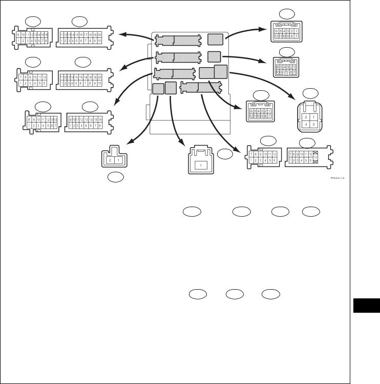
TERMINALS OF ECU
1.CHECK MAIN BODY ECU (INSTRUMENT PANEL J/B)
Front Side:
IJ
IK IM
IE
IL IF
IR
IC ID
IP
IA
IB
Back Side: |
E7 |
E6 |
E8 |
IG |
II |
IH |
IN
IO
E9
LI
E111961E05
(a)Disconnect the IA, ID, IF and IM J/B connectors.
(b)Measure the voltage and resistance between the specified terminals of the wire harness side connectors and body ground.
Standard voltage
Symbols |
Wiring Color |
Terminal Description |
Condition |
Specified Condition |
|
|
|
|
|
IA-1 - Body ground |
B - Body ground |
Battery power supply |
Always |
10 to 14 V |
|
|
|
|
|
LI–18 |
LIGHTING – LIGHTING SYSTEM |
|
|||
|
|
|
|||
|
|
|
|
|
|
Symbols |
|
Wiring Color |
Terminal Description |
Condition |
Specified Condition |
|
|
|
|
|
|
ALTB (ID-16) - Body |
|
W - Body ground |
Generator power supply |
Always |
10 to 14 V |
ground |
|
||||
|
|
|
|
|
|
Standard resistance |
|
|
|
|
|
|
|
|
|
|
|
Symbols |
|
Wiring Color |
Terminal Description |
Condition |
Specified Condition |
|
|
|
|
|
|
GND1 (IF-10) - Body |
|
W-B - Body ground |
Ground |
Always |
Below 1 Ω |
ground |
|
||||
|
|
|
|
|
|
GND2 (IM-9) - Body |
|
W-B - Body ground |
Ground |
Always |
Below 1 Ω |
ground |
|
||||
|
|
|
|
|
|
If the result is not as specified, there may be a malfunction on the wire harness side.
(c)Reconnect the IA, ID, IF, and IM J/B connectors.
(d)Measure the resistance and voltage between the specified terminals of the J/B connectors and body ground.
Standard resistance
Symbols |
Wiring Color |
Terminal Description |
Condition |
Specified Condition |
|
|
|
|
|
|
|
CLTE (E6-18) - Body |
BR - Body ground |
Automatic light control |
Always |
Below 1 Ω |
|
ground |
ground |
||||
|
|
|
Standard voltage
|
|
Symbols |
Wiring Color |
Terminal Description |
Condition |
Specified Condition |
|
|
|
|
|
|
|
|
|
PKB (IC-14) - Body |
|
Parking brake switch |
Parking brake switch ON |
Below 1 V |
|
|
L - Body ground |
|
|
||
|
|
Parking brake switch |
|
|||
|
|
ground (*3) |
input |
10 to 14 V |
||
|
|
|
OFF |
|||
|
|
|
|
|
|
|
|
|
|
|
|
|
|
|
|
|
|
|
Light control switch in |
Below 1 V |
|
|
HRLY (ID-3) - Body |
|
Headlight relay drive |
HEAD |
|
|
|
P - Body ground |
|
|||
|
|
ground |
output |
Light control switch not |
10 to 14 V |
|
|
|
|
||||
|
|
|
|
|
in HEAD |
|
|
|
|
|
|
|
|
|
|
|
|
|
|
|
|
|
DRL (ID-9) - Body |
|
High beam headlights |
Dimmer switch in HIGH |
Below 1 V |
|
|
V - Body ground |
or HIGH FLASH |
|||
|
|
ground |
drive output |
|
||
|
|
|
Dimmer switch in LOW |
10 to 14 V |
||
|
|
|
|
|
||
|
|
|
|
|
|
|
|
|
|
|
Dimmer switch HIGH |
Dimmer switch in HIGH |
10 to 14 V |
|
|
HU (IG-5) - Body ground |
LG - Body ground |
or HIGH FLASH |
||
|
|
input |
|
|||
|
|
|
|
Dimmer switch in LOW |
Below 1 V |
|
|
|
|
|
|
||
|
|
|
|
|
|
|
|
|
|
|
Interior light and ignition |
Interior light and ignition |
Below 1 V |
|
|
ILE (II-10) - Body ground |
|
key cylinder light ON |
||
LI |
|
BR - Body ground |
key cylinder light drive |
|
||
|
(*2) |
Interior light and ignition |
|
|||
|
|
output |
10 to 14 V |
|||
|
|
|
|
|
key cylinder light OFF |
|
|
|
PKB (IM-2) - Body |
|
Parking brake switch |
Parking brake switch ON |
Below 1 V |
|
|
Y - Body ground |
|
|
||
|
|
Parking brake switch |
|
|||
|
|
ground (*4) |
input |
10 to 14 V |
||
|
|
|
OFF (Released) |
|||
|
|
|
|
|
|
|
|
|
|
|
|
|
|
|
|
LCTY (IO-7) - Body |
LG - Body ground |
Rear left door courtesy |
Rear left door open |
Below 1 V |
|
|
ground |
switch input |
Rear left door closed |
10 to 14 V |
|
|
|
|
||||
|
|
|
|
|
|
|
|
|
LSR (IP-5) - Body ground |
GR - Body ground |
Rear left door lock |
Rear left door locked |
10 to 14 V |
|
|
(*2) |
position switch input |
Rear left door unlocked |
Below 1 V |
|
|
|
|||||
|
|
|
|
|
|
|
|
|
LSWL (IP-5) - Body |
GR - Body ground |
Rear left door lock |
Rear left door locked |
10 to 14 V |
|
|
ground (*2) |
position switch input |
Rear left door unlocked |
Below 1 V |
|
|
|
|
||||
|
|
|
|
|
|
|
|
|
|
|
|
Light control switch in |
Below 1 V |
|
|
HEAD (E6-17) - Body |
|
Light control switch |
HEAD |
|
|
|
P - Body ground |
|
|||
|
|
ground |
HEAD input |
Light control switch not |
10 to 14 V |
|
|
|
|
||||
|
|
|
|
|
in HEAD |
|
|
|
|
|
|
|
|
|
|
|
|
|
|
|
|
|
LIGHTING – LIGHTING SYSTEM |
LI–19 |
|
||||
|
|
|
|
|
|
|||
|
|
|
|
|
|
|
|
|
Symbols |
Wiring Color |
|
Terminal Description |
Condition |
Specified Condition |
|
|
|
|
|
|
|
|
|
|
|
|
CLTS (E6-19) - Body |
|
|
Automatic light control |
Ignition switch off |
Below 1 V |
|
|
|
G - Body ground |
|
|
|
|
|
|
||
|
Automatic light control |
Pulse generation |
|
|
|
|||
ground |
|
sensor signal input |
|
|
||||
|
|
system operates |
(See waveform 1) |
|
|
|
||
|
|
|
|
|
|
|||
|
|
|
|
|
|
|
|
|
|
|
|
Automatic light control |
Ignition switch off |
Below 1 V |
|
|
|
CLTB (E6-20) - Body |
|
|
|
|
|
|
|
|
|
|
Ignition switch on (IG) |
|
|
|
|
||
B - Body ground |
|
sensor power supply |
|
|
|
|
||
ground |
|
and light control switch |
10 to 14 V |
|
|
|
||
|
|
output |
|
|
||||
|
|
|
in AUTO |
|
|
|
|
|
|
|
|
|
|
|
|
|
|
|
|
|
|
|
|
|
|
|
|
|
|
|
Passenger side door |
Below 1 V |
|
|
|
PCTY (E6-21) - Body |
|
|
Passenger side door |
open |
|
|
||
Y - Body ground |
|
|
|
|
|
|||
ground |
|
courtesy switch input |
Passenger side door |
10 to 14 V |
|
|
|
|
|
|
|
|
|
||||
|
|
|
|
closed |
|
|
||
|
|
|
|
|
|
|
|
|
|
|
|
|
|
|
|
|
|
|
|
|
|
Luggage compartment |
Below 1 V |
|
|
|
LGCY (E6-25) - Body |
|
|
Luggage courtesy |
door open |
|
|
||
W - Body ground |
|
|
|
|
|
|||
ground |
|
switch input |
Luggage compartment |
10 to 14 V |
|
|
|
|
|
|
|
|
|
||||
|
|
|
|
door closed |
|
|
||
|
|
|
|
|
|
|
|
|
|
|
|
|
|
|
|
|
|
|
|
|
Passenger side door |
Passenger side door |
10 to 14 V |
|
|
|
LSWP (E6-27) - Body |
|
|
locked |
|
|
|||
LG - Body ground |
|
lock position switch |
|
|
|
|
||
ground |
|
Passenger side door |
|
|
|
|
||
|
|
input |
Below 1 V |
|
|
|
||
|
|
|
unlocked |
|
|
|||
|
|
|
|
|
|
|
|
|
|
|
|
|
|
|
|
|
|
|
|
|
|
Front fog light switch |
Below 1 V |
|
|
|
FFOG (E6-28) - Body |
|
|
Front fog light switch |
ON |
|
|
||
V - Body ground |
|
|
|
|
|
|||
ground |
|
input |
Front fog light switch |
10 to 14 V |
|
|
|
|
|
|
|
|
|
||||
|
|
|
|
OFF |
|
|
||
|
|
|
|
|
|
|
|
|
|
|
|
|
|
|
|
|
|
LSWR (E6-5) - Body |
|
|
Rear right door lock |
Rear right door locked |
10 to 14 V |
|
|
|
V - Body ground |
|
|
|
|
|
|
||
|
Rear right door |
|
|
|
|
|||
ground (*1) |
|
position switch input |
Below 1 V |
|
|
|
||
|
|
unlocked |
|
|
||||
|
|
|
|
|
|
|
|
|
|
|
|
|
|
|
|
|
|
RCTY (E6-5) - Body |
GR - Body ground |
|
Rear right door courtesy |
Rear right door open |
Below 1 V |
|
|
|
ground (*2) |
|
switch input |
Rear right door closed |
10 to 14 V |
|
|
|
|
|
|
|
|
|||||
|
|
|
|
|
|
|
|
|
RCTY (E6-7) - Body |
GR - Body ground |
|
Rear right door courtesy |
Rear right door open |
Below 1 V |
|
|
|
ground (*1) |
|
switch input |
Rear right door closed |
10 to 14 V |
|
|
|
|
|
|
|
|
|||||
|
|
|
|
|
|
|
|
|
|
|
|
|
Dimmer switch in HIGH |
Below 1 V |
|
|
|
HF (E7-13) - Body |
|
|
Dimmer switch HIGH |
FLASH position |
|
|
||
R - Body ground |
|
|
|
|
|
|||
ground |
|
FLASH signal input |
Dimmer switch not in |
10 to 14 V |
|
|
|
|
|
|
|
|
|
||||
|
|
|
|
HIGH FLASH position |
|
|
||
|
|
|
|
|
|
|
|
|
|
|
|
|
|
|
|
|
|
SSW2 (E7-16) - Body |
|
|
|
Engine switch not |
10 to 14 V |
|
|
|
V - Body ground |
|
Engine switch input |
pushed |
|
|
|||
ground (*1) |
|
|
|
|
|
|||
|
|
|
Engine switch pushed |
Below 1 V |
|
|
|
|
|
|
|
|
|
|
|||
|
|
|
|
|
|
|
|
|
|
|
|
|
Engine switch not |
|
|
|
|
SSW1 (E7-17) - Body |
|
|
|
10 to 14 V |
|
|
LI |
|
L - Body ground |
|
Engine switch input |
pushed |
|
||||
ground (*1) |
|
|
|
|
||||
|
|
|
Engine switch pushed |
Below 1 V |
|
|
||
|
|
|
|
|
|
|||
|
|
|
|
|
|
|
|
|
|
|
|
|
Light control switch in |
Below 1 V |
|
|
|
|
|
|
Light control switch |
AUTO |
|
|
||
A (E7-21) - Body ground |
G - Body ground |
|
|
|
|
|
||
|
AUTO signal input |
Light control switch not |
10 to 14 V |
|
|
|
||
|
|
|
|
|
|
|||
|
|
|
|
in AUTO |
|
|
||
|
|
|
|
|
|
|
|
|
|
|
|
|
|
|
|
|
|
ACCD (E7-22) - Body |
W - Body ground |
|
Accessory relay drive |
Ignition switch on (ACC) |
Below 1 V |
|
|
|
ground (*1) |
|
output |
Ignition switch off |
10 to 14 V |
|
|
|
|
|
|
|
|
|||||
|
|
|
|
|
|
|
|
|
|
|
|
|
Light control switch in |
Below 1 V |
|
|
|
TAIL (E7-23) - Body |
|
|
Light control switch |
TAIL or HEAD |
|
|
||
B - Body ground |
|
|
|
|
|
|||
ground |
|
TAIL signal input |
Light control switch in |
10 to 14 V |
|
|
|
|
|
|
|
|
|
||||
|
|
|
|
neither TAIL nor HEAD |
|
|
||
|
|
|
|
|
|
|
|
|
|
|
|
|
|
|
|
|
|
DCTY (E7-24) - Body |
L - Body ground |
|
Driver side door |
Driver side door open |
Below 1 V |
|
|
|
ground |
|
courtesy switch input |
Driver side door closed |
10 to 14 V |
|
|
|
|
|
|
|
|
|||||
|
|
|
|
|
|
|
|
|
IG1D (E7-3) - Body |
P - Body ground |
|
Ignition 1 relay drive |
Ignition switch on (IG) |
Below 1 V |
|
|
|
ground (*1) |
|
output |
Ignition switch off |
10 to 14 V |
|
|
|
|
|
|
|
|
|||||
|
|
|
|
|
|
|
|
|

LI–20 |
|
LIGHTING – LIGHTING SYSTEM |
|
||
|
|
|
|||
|
|
|
|
|
|
Symbols |
Wiring Color |
|
Terminal Description |
Condition |
Specified Condition |
|
|
|
|
|
|
|
|
|
|
Light control switch in |
|
FFGO (E7-4) - Body |
|
|
Front fog light relay |
HEAD and front fog light |
Below 1 V |
R - Body ground |
|
switch ON |
|
||
ground |
|
drive output |
|
||
|
|
Front fog light switch |
10 to 14 V |
||
|
|
|
|
||
|
|
|
|
OFF |
|
|
|
|
|
|
|
|
|
|
|
|
|
LSWD (E7-9) - Body |
|
|
Driver side door lock |
Driver side door locked |
10 to 14 V |
L - Body ground |
|
|
|
||
|
Driver side door |
|
|||
ground |
|
position switch input |
Below 1 V |
||
|
|
unlocked |
|||
|
|
|
|
|
|
|
|
|
|
|
|
CANH (E8-5) - Body |
R - Body ground |
|
Control system CAN |
Ignition switch on (IG) |
Pulse generation |
ground |
|
communication |
Ignition switch off |
Below 1 V |
|
|
|
||||
|
|
|
|
|
|
CANL (E8-6) - Body |
W - Body ground |
|
Control system CAN |
Ignition switch on (IG) |
Pulse generation |
ground |
|
communication |
Ignition switch off |
Below 1 V |
|
|
|
||||
|
|
|
|
|
|
GND |
A |
B113714E01 |
If the result is not as specified, the main body ECU (Instrument panel J/B) may have a malfunction. HINT:
*1: with smart key system *2: without smart key system *3: Pedal type parking brake *4: Lever type parking brake
(1) Waveform 1
Item |
|
Contents |
|
|
|
Tool setting |
|
5 V/DIV., 5 ms./DIV. |
|
|
|
|
HINT: |
|
|
If the ambient light becomes brighter, width A |
|
|
becomes narrower. |
|
LI
LIGHTING – LIGHTING SYSTEM |
LI–21 |
|
DIAGNOSIS SYSTEM
1.DESCRIPTION
(a)Lighting system data and the Diagnostic Trouble Codes (DTCs) can be read from the Data Link Connector 3 (DLC3) of the vehicle. When the system seems to be malfunctioning, use the intelligent tester to check for malfunctions and perform repairs.
CG |
SG CANH |
SIL |
|
CANL |
BAT |
|
|
H100769E16 |
2.CHECK DLC3
(a)The ECU uses ISO 15765-4 for communication. The terminal arrangement of the DLC3 complies with SAE J1962 and matches the ISO 15765-4 format.
Symbols (Terminal No.) |
Terminal Description |
Condition |
Specified Condition |
|
|
|
|
SIL (7) - SG (5) |
Bus "+" line |
During transmission |
Pulse generation |
|
|
|
|
CG (4) - Body ground |
Chassis ground |
Always |
Below 1 Ω |
|
|
|
|
SG (5) - Body ground |
Signal ground |
Always |
Below 1 Ω |
|
|
|
|
BAT (16) - Body ground |
Battery positive |
Always |
11 to 14 V |
|
|
|
|
CANH (6) - CANL (14) |
CAN bus line |
Ignition switch off* |
54 to 69 Ω |
|
|
|
|
CANH (6) - CG (4) |
HIGH-level CAN bus line |
Ignition switch off* |
200 Ω or higher |
|
|
|
|
CANL (14) - CG (4) |
LOW-level CAN bus line |
Ignition switch off* |
200 Ω or higher |
|
|
|
|
CANH (6) - BAT (16) |
HIGH-level CAN bus line |
Ignition switch off* |
6 kΩ or higher |
|
|
|
|
CANL (14) - BAT (16) |
LOW-level CAN bus line |
Ignition switch off* |
6 kΩ or higher |
|
|
|
|
NOTICE: |
|
|
*Before measuring the resistance, leave the |
|
|
vehicle as is for at least 1minute and do not |
|
|
operate the ignition switch, any other switches, |
|
|
or the doors. |
|
|
If the result is not as specified, the DLC3 may have |
LI |
|
a malfunction. Repair or replace the harness and |
||
connector. |
||
|
LI–22 |
LIGHTING – LIGHTING SYSTEM |
|
Intelligent Tester |
|
(b) |
Connect the cable of the intelligent tester to the |
|
|
DLC3, turn the ignition switch on (IG) and attempt to |
|
|
|
|
use the tester. If the display indicates that a |
|
|
|
communication error has occurred, there is a |
|
|
|
problem either with the vehicle or with the tester. |
|
|
|
HINT: |
|
|
|
• If communication is normal when the tester is |
|
|
|
connected to another vehicle, inspect the DLC3 |
|
|
|
of the original vehicle. |
|
|
|
• If communication is still not possible when the |
|
|
|
tester is connected to another vehicle, the |
|
|
|
problem may be in the tester itself. Consult the |
DLC3 |
|
|
Service Department listed in the tester's |
|
|
instruction manual. |
|
CAN VIM |
3. |
INSPECT BATTERY VOLTAGE |
|
|
|||
|
C131977E10 |
Standard voltage: |
|
|
|
||
|
|
11 to 14 V |
|
|
|
If the voltage is below 11 V, recharge or replace the |
|
|
|
battery before proceeding. |
|
Intelligent Tester |
DTC CHECK / CLEAR |
||
|
1. |
CHECK DTC |
|
|
|
(a) |
Connect the intelligent tester to the DLC3. |
|
|
(b) |
Turn the ignition switch on (IG). |
|
|
(c) |
Read the DTCs by following the directions on the |
|
|
|
tester screen. |
|
|
|
HINT: |
|
|
|
Please refer to the intelligent tester operator's |
|
|
|
manual for further details. |
|
2. |
CLEAR DTC |
|
|
|
(a) |
Connect the intelligent tester to the DLC3. |
DLC3 |
|
(b) |
Turn the ignition switch on (IG). |
|
(c) |
Erase the DTCs by following the directions on the |
|
CAN VIM |
|
|
tester screen. |
|
|
|
|
|
C131977E10 |
|
HINT: |
|
|
|
|
|
|
|
Please refer to the intelligent tester operator's |
|
|
|
manual for further details. |
LI
LIGHTING – LIGHTING SYSTEM |
LI–23 |
|
DATA LIST / ACTIVE TEST
1.READ DATA LIST
HINT:
Using the intelligent tester DATA LIST allows switch, actuator and other item values to be read without removing any parts. Reading the DATA LIST early in troubleshooting is one way to save time.
(a)Connect the intelligent tester to the DLC3.
(b)Turn the ignition switch on (IG).
(c)Read the DATA LIST according to the display on the tester.
MAIN BODY (MAIN BODY ECU):
Item |
Measurement Item / Display |
Normal Condition |
Diagnostic Note |
|
|
|
(Range) |
|
|
||||
|
|
|
|
|
||
|
|
|
|
|
|
|
|
Ignition switch or engine switch |
ON: Ignition switch on (ACC or |
|
|
|
|
ACC SW |
IG) |
- |
|
|
||
ACC signal / ON or OFF |
|
|
||||
|
OFF: Ignition switch off |
|
|
|
||
|
|
|
|
|
||
|
|
|
|
|
|
|
IG SW |
Ignition switch or engine switch |
ON: Ignition switch on (IG) |
- |
|
|
|
IG signal / ON or OFF |
OFF: Ignition switch off |
|
|
|||
|
|
|
|
|||
|
|
|
|
|
|
|
D DOR CTY SW |
Driver side door courtesy switch |
ON: Driver side door is open |
- |
|
|
|
signal / ON or OFF |
OFF: Driver side door is closed |
|
|
|||
|
|
|
|
|||
|
|
|
|
|
|
|
|
|
ON: Front passenger side door is |
|
|
|
|
P DOR CTY SW |
Passenger side door courtesy |
open |
- |
|
|
|
switch signal / ON or OFF |
OFF: Front passenger side door |
|
|
|||
|
|
|
|
|||
|
|
is closed |
|
|
|
|
|
|
|
|
|
|
|
RR DOR CTY SW |
Rear right door courtesy switch |
ON: Rear right door is open |
- |
|
|
|
signal / ON or OFF |
OFF: Rear right door is closed |
|
|
|||
|
|
|
|
|||
|
|
|
|
|
|
|
RL DOR CTY SW |
Rear left door courtesy switch |
ON: Rear left door is open |
- |
|
|
|
signal / ON or OFF |
OFF: Rear left door is closed |
|
|
|||
|
|
|
|
|||
|
|
|
|
|
|
|
D LOCK POS SW |
Driver side door lock position |
ON: Driver side door is unlocked |
- |
|
|
|
switch signal / ON or OFF |
OFF: Driver side door is locked |
|
|
|||
|
|
|
|
|||
|
|
|
|
|
|
|
|
|
ON: Front passenger side door is |
|
|
|
|
P LOCK POS SW |
Passenger side door lock position |
unlocked |
- |
|
|
|
switch signal / ON or OFF |
OFF: Front passenger side door |
|
|
|||
|
|
|
|
|||
|
|
is locked |
|
|
|
|
|
|
|
|
|
|
|
RR LOCK POS SW |
Rear right door lock position |
ON: Rear right door is unlocked |
- |
|
|
|
(with Smart Key System) |
switch signal / ON or OFF |
OFF: Rear right door is locked |
|
|
||
|
|
|
||||
|
|
|
|
|
|
|
RL. LOCK POS SW |
Rear left door lock position switch |
ON: Rear left door is unlocked |
- |
|
|
|
(with Smart Key System) |
signal / ON or OFF |
OFF: Rear left door is locked |
|
|
||
|
|
|
||||
|
|
|
|
|
|
|
|
Dimmer switch HIGH signal / ON |
ON: Dimmer switch in HIGH or |
|
|
LI |
|
DIMMER SW |
HIGH FLASH |
- |
|
|||
or OFF |
|
|||||
|
||||||
|
|
OFF: Dimmer switch in LOW |
|
|
|
|
|
|
ON: Dimmer switch in HIGH |
|
|
|
|
HIGH FLASHER SW |
Dimmer switch HIGH FLASH |
FLASH |
- |
|
|
|
signal / ON or OFF |
OFF: Dimmer switch not in HIGH |
|
|
|||
|
|
|
|
|||
|
|
FLASH |
|
|
|
|
|
|
|
|
|
|
|
F FOG LIGHT SW |
Fog light switch signal / ON or |
ON: Fog light switch ON |
- |
|
|
|
OFF |
OFF: Fog light switch OFF |
|
|
|||
|
|
|
|
|||
|
|
|
|
|
|
|
|
Light control switch AUTO signal / |
ON: Light control switch in AUTO |
|
|
|
|
AUTO LIGHT SW |
OFF: Light control switch not in |
- |
|
|
||
ON or OFF |
|
|
||||
|
AUTO |
|
|
|
||
|
|
|
|
|
||
|
|
|
|
|
|
|
HEAD LIGHT SW |
Light control switch HEAD signal / |
ON: Light control switch in HEAD |
|
|
|
|
OFF: Light control switch not in |
- |
|
|
|||
ON or OFF |
|
|
||||
|
HEAD |
|
|
|
||
|
|
|
|
|
||
|
|
|
|
|
|
|
|
|
ON: Light control switch in TAIL or |
|
|
|
|
TAIL LIGHT SW |
Light control switch TAIL signal / |
HEAD |
- |
|
|
|
ON or OFF |
OFF: Light control switch not in |
|
|
|||
|
|
|
|
|||
|
|
TAIL or HEAD |
|
|
|
|
|
|
|
|
|
|

LI–24 |
LIGHTING – LIGHTING SYSTEM |
|
||
|
|
|||
|
|
|
|
|
Item |
Measurement Item / Display |
Normal Condition |
Diagnostic Note |
|
(Range) |
||||
|
|
|
||
|
|
|
|
|
|
Illumination rate information / 0 |
0.8 ms. to 22.0 ms. (Value is |
|
|
ILLUMINATE RATE |
output according to ambient |
- |
||
ms. to 99.99 ms. |
||||
|
illuminance) |
|
||
|
|
|
||
|
|
|
|
|
PARKING BRAKE SW |
Parking brake switch signal / ON |
ON: Parking brake switch is ON |
- |
|
or OFF |
OFF: Parking brake switch is OFF |
|||
|
|
|||
|
|
|
|
|
2.PERFORM ACTIVE TEST
HINT:
Performing the intelligent tester ACTIVE TEST allows a relay, VSV, actuator, and other items to be operated without removing any parts. Performing the ACTIVE TEST early in troubleshooting is one way to save time. The DATA LIST can be displayed during the ACTIVE TEST.
(a)Connect the intelligent tester to the DLC3.
(b)Turn the ignition switch on (IG).
(c)Perform the ACTIVE TEST according to the display on the tester.
MAIN BODY (MAIN BODY ECU):
Item |
Test Details |
Diagnostic Note |
|
|
|
F FOG LIGHT RLY |
Front fog light relay ON / OFF |
- |
|
|
|
HEAD LIGHT |
Headlight relay ON / OFF |
- |
|
|
|
HEAD LIGHT (HI) |
High beam headlights ON / OFF |
- |
|
|
|
TAIL LIGHT |
Taillight ON / OFF |
- |
|
|
|
DIMMER SIG |
Dimmer signal ON / OFF |
- |
|
|
|
|
Interior light and ignition key cylinder light ON |
|
ILLUMI OUTPUT |
/ OFF (Interior light switch in DOOR position |
- |
|
and all doors are closed) |
|
|
|
|
LI

LIGHTING – LIGHTING SYSTEM |
LI–25 |
|
DIAGNOSTIC TROUBLE CODE CHART
LIGHTING SYSTEM:
DTC No. |
Detection Item |
|
Suspected Area |
See page |
|
|
|
|
|
B1244 |
Light Sensor Circuit Malfunction |
1. |
Automatic light control sensor |
LI-23 |
|
|
2. |
Harness or connector |
|
|
|
3. |
Main body ECU (Instrument |
|
|
|
panel J/B) |
|
|
|
|
|
|
|
LI
LI–26 |
|
LIGHTING – LIGHTING SYSTEM |
|
|
|
|
|
|
DTC |
B1244 |
Light Sensor Circuit Malfunction |
|
|
|
DESCRIPTION
The automatic light control sensor detects ambient light, converts it into an electrical signal, and outputs it to the main body ECU. The main body ECU turns on or off the headlights and taillights according to the signal.
DTC No. |
|
DTC Detecting Condition |
|
Trouble Area |
|
|
|
|
|
|
• |
Malfunction in automatic light control sensor |
• Automatic light control sensor |
|
B1244 |
• |
Open or short in automatic light control sensor |
• |
Harness or connector |
|
|
circuit |
• |
Main body ECU (Instrument panel J/B) |
|
|
|
|
|
WIRING DIAGRAM
E11 |
|
|
E6 |
|
|
|
Main Body ECU |
||
Automatic Light Control Sensor |
|
|||
|
|
|||
CLTB |
3 (*1) |
|
CLTB |
|
6 (*2) |
20 |
|||
CLTS |
4 (*1) |
|
CLTS |
|
5 (*2) |
19 |
|||
|
|
|||
CLTE |
6 (*1) |
|
CLTE |
|
3 (*2) |
18 |
|||
*1: Manual A/C |
*2: Automatic A/C |
|
|
|
|
|
|
E124321E04 |
|
LI INSPECTION PROCEDURE
1READ VALUE OF INTELLIGENT TESTER
(a)Connect the intelligent tester to the DLC3.
(b)Turn the ignition switch on (IG) and turn the intelligent tester main switch on.
(c)Select the item below in the DATA LIST, and read the
display on the intelligent tester.
MAIN BODY (MAIN BODY ECU):
Item |
Measurement Item / Display |
Normal Condition |
Diagnostic Note |
|
(Range) |
||||
|
|
|
||
|
|
|
|
|
ILLUMINATE RATE |
Illumination rate information / 0 |
0.8 ms to 22.0 ms (Value is output |
- |
|
ms to 99.99 ms |
according to ambient illuminance) |
|||
|
|
|||
|
|
|
|
OK:
Normal condition listed above is displayed.

|
|
LIGHTING – LIGHTING SYSTEM |
LI–27 |
||||
|
|
|
|||||
|
|
|
OK |
|
|
|
|
|
|
|
|
|
REPLACE INSTRUMENT PANEL JUNCTION |
||
|
|
|
|
|
|
BLOCK ASSEMBLY |
|
|
|
|
|
|
|||
|
|
|
|
|
|
||
|
|
|
|
|
|
|
|
NG |
|
|
|
|
|||
|
|
|
|
|
|
||
2 |
CHECK VEHICLE CONDITION |
|
|
|
|
||
|
|
|
|
|
|
||
Result |
|
|
|
|
|||
|
|
|
|
|
|
|
|
|
|
Vehicle Condition |
|
|
Proceed to |
|
|
|
|
|
|
|
|||
Manual Air Conditioning System |
|
|
A |
|
|||
Automatic Air Conditioning System |
|
|
B |
|
|||
|
|
|
|
|
|
|
|
|
|
|
B |
|
|
|
|
|
|
|
|
|
Go to step 6 |
|
|
|
|
|
|
|
|
|
|
A |
|
|
|
|
|
|
|
3 |
CHECK HARNESS AND CONNECTOR (MAIN BODY ECU - AUTOMATIC LIGHT CONTROL |
|
|||||
|
SENSOR) |
|
|
|
|
|
|
|
|
|
(a) Disconnect the E11 automatic light control sensor |
|
|||
Wire Harness Side: |
|
connector. |
|
|
|
||
|
|
|
(b) Disconnect the E6 main body ECU connector. |
|
|||
|
Automatic Light Control Sensor |
(c) Measure the resistance according to the value(s) in the |
|
||||
|
|
|
table below. |
|
|
|
|
|
E11 |
|
Standard resistance |
|
|
|
|
|
CLTB |
CLTS |
|
Tester Connection |
Condition |
Specified |
|
|
|
Condition |
|
||||
|
|
|
|
|
|||
|
|
CLTE |
|
E6-18 (CLTE) - E11-6 (CLTE) |
Always |
Below 1 Ω |
|
|
|
|
|
E6-19 (CLTS) - E11-4 (CLTS) |
Always |
Below 1 Ω |
|
|
Main Body ECU |
|
E6-20 (CLTB) - E11-3 (CLTB) |
Always |
Below 1 Ω |
|
|
|
|
E6-18 (CLTE) - Body ground |
Always |
10 kΩ or higher |
|
||
|
|
|
|
|
|||
E6 |
|
|
|
E6-19 (CLTS) - Body ground |
Always |
10 kΩ or higher |
|
|
|
|
|
E6-20 (CLTB) - Body ground |
Always |
10 kΩ or higher |
|
|
|
|
NG |
REPAIR OR REPLACE HARNESS OR |
LI |
||
|
|
CLTB |
|
CONNECTOR |
|
|
|
|
CLTE |
CLTS |
|
|
|
|
|
|
E121476E03 |
|
|
|
|
|
|
|
|
|
|
|
|
|
|
OK
4INSPECT MAIN BODY ECU (INSTRUMENT PANEL JUNCTION BLOCK ASSEMBLY)
(a)Reconnect the main body ECU connector.

LI–28 |
|
|
|
|
|
|
LIGHTING – LIGHTING SYSTEM |
|
|
|
|
|||||||||||||
|
|
|
|
|
|
|
|
|
|
|
|
|
|
|
|
|||||||||
|
|
|
|
|
|
|
|
|
|
|
|
|
|
(b) Measure the voltage and resistance according to the |
||||||||||
|
Wire Harness Side: |
|
|
|
|
|
|
|
|
|||||||||||||||
|
|
|
|
|
|
|
|
|
value(s) in the table below. |
|
|
|
|
|||||||||||
|
Automatic Light Control Sensor |
|
|
Standard voltage |
|
|
|
|
|
|
||||||||||||||
|
|
|
|
|
|
|
|
|
|
|
|
|
|
Tester Connection |
|
Condition |
|
|
Specified Condition |
|||||
|
|
|
|
|
|
|
|
|
|
|
|
|
|
|
|
|
|
|
|
|
|
|||
|
|
|
|
|
|
|
|
|
|
|
|
|
|
E11-3 (CLTB) - E11-6 |
|
Ignition switch off |
|
|
Below 1 V |
|||||
|
|
|
|
|
|
|
|
|
|
|
|
|
|
|
|
|||||||||
|
|
|
|
|
|
|
|
|
|
|
|
|
|
|
|
(CLTE) |
Ignition switch on (IG) |
|
|
10 to 14 V |
||||
|
E11 |
|
|
|
|
|
|
|
|
CLTS |
|
|
|
|
|
|||||||||
|
|
|
|
|
|
|
|
|
|
|
|
|
|
|||||||||||
|
|
|
|
|
|
|
|
|
|
|
|
|
|
|
|
|
|
|
|
|
|
|||
|
|
|
|
|
|
|
|
|
|
|
Standard resistance |
|
|
|
|
|||||||||
|
|
|
|
|
|
|
|
|
|
|
|
|
|
|||||||||||
|
|
|
|
|
|
|
|
|
|
|
|
|
|
|
|
|
||||||||
|
|
|
|
|
|
|
|
|
|
|
|
|
|
|||||||||||
|
|
|
|
|
|
|
|
|
|
|
CLTE |
|
|
|
|
|
|
|||||||
|
|
|
|
|
|
|
|
|
|
|
|
|
|
|
|
|
|
|
|
|
|
|
|
|
|
CLTB |
|
|
|
|
|
|
|
|
|
|
|
|
|
|
|
|
|
|
|
||||
|
|
|
|
|
|
|
|
|
|
|
Tester Connection |
|
|
Condition |
Specified |
|||||||||
|
|
|
|
|
|
|
|
|
|
|
|
B109993E15 |
|
|
|
|
|
Condition |
||||||
|
|
|
|
|
|
|
|
|
|
|
|
|
|
|
|
|
|
|
|
|
|
|
|
|
|
|
|
|
|
|
|
|
|
|
|
|
|
|
|
|
|
|
|
|
|
||||
|
|
|
|
|
|
|
|
|
|
|
|
|
|
|
E11-6 (CLTE) - Body ground |
|
Always |
|
Below 1 Ω |
|||||
|
|
|
|
|
|
|
|
|
|
|
|
|
|
|
|
|
|
|
|
|
|
|||
|
|
|
|
|
|
|
|
|
|
|
|
|
|
NG |
|
|
|
|
|
|
|
|
|
|
|
|
|
|
|
|
|
|
|
|
|
|
|
|
|
|
REPLACE INSTRUMENT PANEL JUNCTION |
||||||||
|
|
|
|
|
|
|
|
|
|
|
|
|
|
|
|
|
BLOCK ASSEMBLY |
|
|
|
|
|||
|
|
|
|
|
|
|
|
|
|
|
|
|
|
|
|
|
|
|
|
|||||
|
|
|
|
|
|
|
|
|
|
|
|
|
|
|
|
|
|
|
|
|
|
|
|
|
OK
5 INSPECT AUTOMATIC LIGHT CONTROL SENSOR
Automatic Light Control Sensor |
E11 |
CLTS |
CLTE |
E121468E03 |
(a)Reconnect the automatic light control sensor connector.
(b)Connect an oscilloscope to the automatic light control sensor connector.
|
(c) |
Check the waveform. |
|
|
|||
|
|
OK |
|
|
|
|
|
|
|
Tester |
|
Tool Setting |
Condition |
Specified |
|
|
|
Connection |
|
Condition |
|||
|
|
|
|
|
|||
GND |
|
|
|
|
Ignition switch |
Correct |
|
E11-6 (CLTE) - |
5 V/DIV., 5 ms./ |
on (IG), light |
|||||
waveform is as |
|||||||
A |
|
E11-4 (CLTS) |
DIV. |
control switch in |
|||
LI |
|
|
|
|
AUTO |
shown |
|
|
|
|
|
|
|||
|
|
|
|
|
|
||
|
|
HINT: |
|
|
|
|
|
B113714E01 |
|
If the ambient light becomes brighter, width A becomes |
|||||
|
|
narrower. |
|
|
|
||
|
NG |
REPLACE AUTOMATIC LIGHT CONTROL |
|||||
|
|
|
SENSOR |
|
|
||
OK |
|
|
|
|
|
|
|
REPLACE INSTRUMENT PANEL JUNCTION BLOCK ASSEMBLY

LIGHTING – LIGHTING SYSTEM |
LI–29 |
|
6CHECK HARNESS AND CONNECTOR (MAIN BODY ECU - AUTOMATIC LIGHT CONTROL SENSOR)
Wire Harness Side: |
|
|
Automatic Light Control Sensor |
||
E11 |
|
|
CLTE |
|
CLTB |
CLTS |
|
|
|
Main Body ECU |
|
E6 |
|
|
|
|
CLTB |
|
CLTE |
CLTS |
|
E121476E04 |
|
|
|
|
OK |
|
|
(a)Disconnect the E11 automatic light control sensor connector.
(b)Disconnect the E6 main body ECU connector.
Standard resistance
|
|
Tester Connection |
Condition |
Specified |
|
|
|
Condition |
|||
|
|
|
|
|
|
|
|
|
|
|
|
|
|
E6-18 (CLTE) - E11-3 (CLTE) |
Always |
Below 1 Ω |
|
|
|
|
|
|
|
|
|
E6-19 (CLTS) - E11-5 (CLTS) |
Always |
Below 1 Ω |
|
|
|
|
|
|
|
|
|
E6-20 (CLTB) - E11-6 (CLTB) |
Always |
Below 1 Ω |
|
|
|
|
|
|
|
|
|
E6-18 (CLTE) - Body ground |
Always |
10 kΩ or higher |
|
|
|
|
|
|
|
|
|
E6-19 (CLTS) - Body ground |
Always |
10 kΩ or higher |
|
|
|
|
|
|
|
|
|
E6-20 (CLTB) - Body ground |
Always |
10 kΩ or higher |
|
|
|
|
|
|
|
|
NG |
|
|
||
|
|
REPAIR OR REPLACE HARNESS OR |
|||
|
|
|
CONNECTOR |
|
|
|
|
|
|
||
|
|
|
|
|
|
7INSPECT MAIN BODY ECU (INSTRUMENT PANEL JUNCTION BLOCK ASSEMBLY )
(a)Reconnect the main body ECU connector.
(b)Measure the voltage and resistance according to the
Wire Harness Side: |
|
|
|
|
|
|
|
|
value(s) in the table below. |
|
|
|
|
|
|
||||||||||
Automatic Light Control Sensor |
|
|
Standard voltage |
|
|
|
|
|
|
|
|
||||||||||||||
|
|
|
|
|
|
|
|
|
|
|
|
|
Tester Connection |
|
Condition |
|
|
Specified Condition |
|
|
|||||
|
|
|
|
|
|
|
|
|
|
|
|
|
|
|
|
|
|
|
|
|
|
|
|
||
|
|
|
|
|
|
|
|
|
|
|
|
|
E11-6 (CLTB) - E11-3 |
|
|
|
|
|
|
|
|
|
|||
|
|
|
|
|
|
|
|
|
|
|
|
Ignition switch off |
|
|
Below 1 V |
|
LI |
||||||||
|
|
|
|
|
|
|
|
|
|
|
|
|
|
|
(CLTE) |
|
|
|
|
||||||
|
|
|
|
|
|
|
|
|
|
|
|
|
|
|
|
|
|
|
|
||||||
E11 |
|
|
|
|
|
|
|
|
|
|
|
|
|
|
|
|
|
|
|
|
|
|
|||
|
|
|
|
|
|
|
|
|
|
|
|
|
|
|
|
|
|
|
|
|
|
|
|
||
|
|
|
|
|
|
|
|
CLTE |
|
|
E11-6 (CLTB) - E11-3 |
Ignition switch on (IG) |
|
|
10 to 14 V |
|
|
||||||||
|
|
|
|
|
|
|
|
|
|
|
|
|
|
||||||||||||
|
|
|
|
|
|
|
|
|
|
|
|
|
|
||||||||||||
|
|
|
|
|
|
|
|
|
|
|
|
|
|
||||||||||||
|
|
|
|
|
|
|
|
|
|
|
|
|
|
(CLTE) |
|
|
|
|
|||||||
|
|
|
|
|
|
|
|
|
|
|
|
|
|||||||||||||
|
|
|
|
|
|
|
|
|
|
CLTB |
|
|
|
|
|
|
|
|
|
|
|
|
|
||
|
|
|
|
|
|
|
|
|
|
|
|
|
|
|
|
|
|
|
|||||||
|
|
|
|
|
|
|
|
|
|
|
|
|
|
|
|
|
|
|
|||||||
|
|
|
|
|
|
|
|
|
|
|
|
|
Standard resistance |
|
|
|
|
|
|
||||||
|
|
|
|
|
|
|
|
|
|
|
|
|
|
|
|
|
|
|
|||||||
|
|
|
|
|
|
|
|
|
|
|
B109993E16 |
|
|
|
|
|
|
|
|
|
|
|
|
||
|
|
|
|
|
|
|
|
|
|
|
|
|
|
|
Tester Connection |
|
|
Condition |
Specified |
|
|
||||
|
|
|
|
|
|
|
|
|
|
|
|
|
|
|
|
|
|
||||||||
|
|
|
|
|
|
|
|
|
|
|
|
|
|
|
|
|
Condition |
|
|
||||||
|
|
|
|
|
|
|
|
|
|
|
|
|
|
|
|
|
|
|
|
|
|
|
|
|
|
|
|
|
|
|
|
|
|
|
|
|
|
|
|
|
|
|
|
|
|
|
|
||||
|
|
|
|
|
|
|
|
|
|
|
|
|
|
E11-3 (CLTE) - Body ground |
|
Always |
|
Below 1 Ω |
|
|
|||||
|
|
|
|
|
|
|
|
|
|
|
|
|
|
|
|
|
|
|
|
|
|
|
|||
|
|
|
|
|
|
|
|
|
|
|
|
|
NG |
|
|
|
|
|
|
|
|
|
|
|
|
|
|
|
|
|
|
|
|
|
|
|
|
|
|
|
REPLACE INSTRUMENT PANEL JUNCTION |
|
|
||||||||
|
|
|
|
|
|
|
|
|
|
|
|
|
|
|
|
BLOCK ASSEMBLY |
|
|
|
|
|
|
|||
|
|
|
|
|
|
|
|
|
|
|
|
|
|
|
|
|
|
|
|
|
|||||
|
|
|
|
|
|
|
|
|
|
|
|
|
|
|
|
|
|
|
|
|
|
|
|
|
|
OK
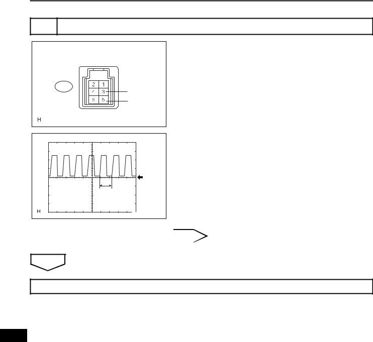
LI–30 |
LIGHTING – LIGHTING SYSTEM |
|
8 INSPECT AUTOMATIC LIGHT CONTROL SENSOR
Automatic Light Control Sensor |
|
E11 |
CLTE |
|
|
|
CLTS |
|
E121468E04 |
(a)Reconnect the automatic light control sensor connector.
(b)Connect an oscilloscope to the automatic light control sensor connector.
GND |
A |
B113714E01 |
OK
(c) Check the waveform.
OK
Tester |
Tool Setting |
Condition |
Specified |
|
Connection |
Condition |
|||
|
|
|||
|
|
|
|
|
|
|
Ignition switch |
Correct |
|
E11-3 (CLTE) - |
5 V/DIV., 5 ms./ |
on (IG), light |
||
waveform is as |
||||
E11-5 (CLTS) |
DIV. |
control switch in |
||
shown |
||||
|
|
AUTO |
||
|
|
|
||
|
|
|
|
HINT:
If the ambient light becomes brighter, width A becomes narrower.
NG |
|
REPLACE AUTOMATIC LIGHT CONTROL |
|
|
SENSOR |
|
||
|
|
|
REPLACE INSTRUMENT PANEL JUNCTION BLOCK ASSEMBLY
LI
 Loading...