


|
POWER STEERING – POWER STEERING SYSTEM |
PS–1 |
A-PDF |
Merger DEMO : Purchase from www.A-PDF.com to remove the watermark |
|
|
|
POWER STEERING SYSTEM
PRECAUTION
NOTICE:
When disconnecting the cable from the negative (-) battery terminal, initialize the systems after the cable is reconnected (See page IN-43).
1.HANDLING PRECAUTIONS FOR STEERING SYSTEM
(a)Care must be taken when replacing parts. Incorrect replacement may affect the performance of the steering system and result in driving hazards.
2.HANDLING PRECAUTIONS FOR SRS AIRBAG SYSTEM
(a)The vehicle is equipped with SRS (Supplemental Restraint System), such as airbags. If service operation is not carried out properly, in a step by step fashion, sudden deployment of the airbags may result in serious injury. Before servicing (including removal or installation of parts, inspection or replacement), be sure to read the precautionary notice for the supplemental restraint system (See page RS-1).
3.PRECAUTIONS FOR REMOVAL, INSTALLATION AND REPLACEMENT OF ELECTRONIC MOTOR POWER STEERING COMPONENTS
(a)Be sure to turn the front wheels straight ahead when removing and installing the power steering link assembly.
(b)If disconnecting the steering intermediate shaft subassembly and the power steering link assembly, be sure to put matchmarks before starting the operation.
(c)After replacing the power steering link assembly or power steering ECU assembly, clear the rotation angle sensor calibration value, initialize the rotation angle sensor, and calibrate torque sensor zero point (See page PS-13).
PS

PS–2 |
POWER STEERING – POWER STEERING SYSTEM |
|
PROBLEM SYMPTOMS TABLE
HINT:
Use the table below to help determine the cause of the problem. The numbers indicate likely causes of the problem in descending order. Check each part in order. If necessary, repair or replace faulty parts.
POWER STEERING SYSTEM
|
|
Symptom |
|
Suspected Area |
See page |
|
|
|
|
|
|
|
|
|
1. |
Front tires (Improperly inflated, unevenly worn) |
TW-3 |
|
|
|
|
|
|
|
|
|
2. |
Front wheel alignment (Incorrect) |
SP-4 |
|
|
|
|
|
|
|
|
|
3. |
Front suspension (Lower ball joint) |
SP-24 |
|
|
|
|
|
|
|
|
|
4. |
Steering column assembly |
SR-35 |
|
|
|
|
|
|
|
|
|
5. |
Torque sensor (Built into steering link assembly) |
- |
|
|
Steering is heavy. |
|
|
|
|
|
6. Power steering motor |
- |
||
|
|
|
|
|
|
|
|
|
7. |
Speed sensor |
- |
|
|
|
|
|
|
|
|
|
8. |
Skid control ECU |
- |
|
|
|
|
|
|
|
|
|
9. |
Battery and power source system |
- |
|
|
|
|
|
|
|
|
|
10. Power steering ECU power source voltage and relay |
- |
|
|
|
|
|
|
|
|
|
|
11. Power steering ECU |
PS-68 |
|
|
|
|
|
|
|
|
|
|
1. Calibration of turning angle sensor output and torque sensor |
PS-13 |
|
|
|
|
zero point is not completed |
||
|
|
|
|
||
|
|
|
|
|
|
|
|
|
2. |
Front tires (Improperly inflated, unevenly worn) |
TW-3 |
|
|
|
|
|
|
|
|
|
3. |
Front wheel alignment (Incorrect) |
SP-4 |
|
|
|
|
|
|
|
|
Steering effort differs between right and left or is |
4. |
Front suspension (Lower ball joint) |
SP-24 |
|
|
|
|
|
|
|
|
uneven. |
5. Power steering link assembly |
PS-58 |
|
|
|
|
|
|
|
|
|
|
6. |
Torque sensor (Built into steering link assembly) |
- |
|
|
|
|
|
|
|
|
|
7. |
Steering column assembly |
SR-35 |
|
|
|
|
|
|
|
|
|
8. |
Power steering motor |
- |
|
|
|
|
|
|
|
|
|
9. |
Power steering ECU |
PS-68 |
|
|
|
|
|
|
|
|
|
1. |
Front suspension (Lower ball joint) |
SP-24 |
|
|
|
|
|
|
|
|
|
2. |
Speed sensor |
- |
|
|
|
|
|
|
|
|
|
3. |
Skid control ECU |
- |
|
|
While driving, steering effort does not change in |
|
|
|
|
|
4. |
Combination meter |
- |
|
|
|
accordance with vehicle speed or the steering wheel |
|||
|
|
|
|
|
|
|
|
5. |
Engine speed detection circuit |
- |
|
|
|
does not return properly. |
|||
|
|
|
|
|
|
|
|
|
6. |
Torque sensor (Built into steering link assembly) |
- |
|
|
|
|
|
|
|
|
|
7. |
Power steering motor |
- |
|
|
|
|
|
|
|
|
|
8. |
Power steering ECU |
PS-68 |
|
|
|
|
|
|
|
|
A knocking (or cranking) sound occurs when turning |
1. |
Front suspension (Lower ball joint) |
SP-24 |
|
|
|
|
|
|
|
|
the steering wheel back and forth while power steering |
2. Steering intermediate shaft |
- |
|
|
|
is in operation. |
|
|
|
|
|
3. |
Power steering link assembly |
PS-58 |
|
|
|
|
|||
|
|
|
|
|
|
|
|
Noise occurs when turning the steering wheel during |
1. Power steering link assembly |
PS-58 |
|
|
|
low speed driving. |
2. Steering column assembly |
SR-35 |
|
|
|
|
|
|
|
|
|
A high-pitched sound (squeaking) occurs when turning |
1. Power steering motor |
- |
|
|
|
the steering wheel slowly with the vehicle stopped. |
|
|
|
|
|
|
|
|
|
|
|
|
|
|
|
|
|
The steering wheel vibrates and noise occurs when |
1. Power steering link assembly |
PS-58 |
|
PS |
|||||
|
|
turning the steering wheel from lock to lock. |
2. Steering column assembly |
SR-35 |
|
|
|
|
|
|
|
POWER STEERING – POWER STEERING SYSTEM |
PS–3 |
|
C132536 |
ON-VEHICLE INSPECTION
1.CHECK STEERING EFFORT (TORQUE) NOTICE:
Some service operations affect the SRS airbags. Be sure to read the precautionary notice for the SRS airbags before servicing (See page RS-1).
(a)Stop the vehicle on a level, paved surface and align the wheels straight ahead.
(b)Disconnect the cable from the negative (-) battery terminal.
CAUTION:
Wait at least 90 seconds after disconnecting the cable from the negative (-) battery terminal to prevent airbag and seat belt pretensioner activation.
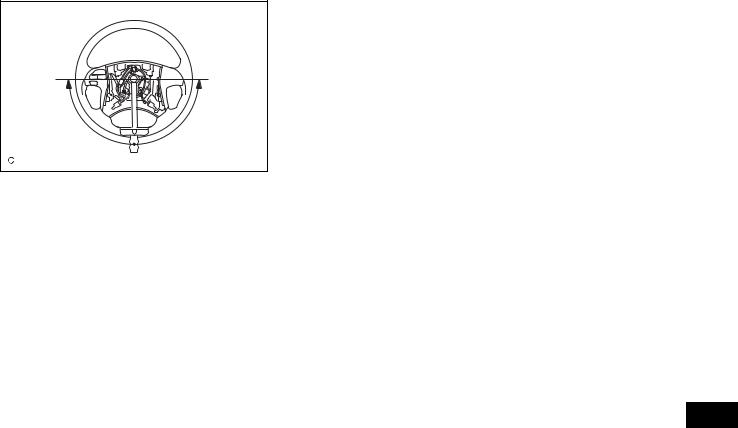
(c)Remove the steering pad (See page RS-344).
(d)Connect the cable to the negative (-) battery terminal.
(e)Using a torque wrench, check if the steering wheel set nut is properly tightened.
Torque: 50 N*m (510 kgf*cm, 37 ft.*lbf)
(f)Turn the power switch on (READY) so that the power steering is available.
(g)Turn the steering wheel 90 degrees to the right and check steering effort (torque) while turning. Check in
the opposite direction using the same manner.
Steering effort (Reference):
6.0 N*m (60 kgf*cm, 53 in.*lbf) or less
Inspect the power steering system if the value is not within the specified range (See page PS-1).
(h)Align the front wheels straight ahead.
(i)Disconnect the cable from the negative (-) battery terminal.
(j)Install the steering pad (See page RS-346).
(k)Connect the cable to the negative (-) battery terminal.
(l)Clear the DTCs (See page RS-41).
(m)Perform initialization.
NOTICE:
Some systems need initialization after reconnecting the cable to the negative battery terminal (See page IN-43).
(n)Inspect the airbag warning light (See Page RS-33).
PS

PS–4
PS
POWER STEERING – ELECTRONIC POWER STEERING SYSTEM
ELECTRONIC POWER STEERING SYSTEM
PRECAUTION
1. NOTICE FOR INITIALIZATION
(a) When disconnecting the negative (-) battery terminal, initialize the following systems after the terminal is reconnected.
System Name |
See procedure |
|
|
SFI System |
(See page IN-43) |
|
|
2. HANDLING PRECAUTIONS
(a) When handling the electronic parts:
(1) Avoid any impact to electronic parts such as ECUs and relays. Replace these parts with new ones if dropped or subjected to a severe blow.
(2) Do not expose any electronic parts to high temperature or humidity.
(3) Do not touch the connector terminals in order to prevent deformation or malfunctions due to static electricity.
(4) If the power steering ECU assembly has been replaced with a new one, initialize the rotation angle sensor value and calibrate the torque sensor zero point (See page PS-13).
(b) When handling the power steering link assembly:
(1) Avoid any impact to the power steering link assembly, especially to the motor or torque sensor. Replace these parts with new ones if dropped or subjected to a severe blow.
(2) Do not pull on the wire harness when moving the power steering link assembly.
(3) If the power steering link assembly has been replaced with a new one, clear the rotation angle sensor calibration value, initialize the rotation angle sensor value, and calibrate the torque sensor zero point (See page PS-13).
(c) When disconnecting and reconnecting the connectors:
(1) Turn the power switch on (IG), center the steering wheel, and turn the power switch off again before disconnecting the connectors related to the electronic power steering system.
(2) Ensure that the power switch is off before reconnecting the connectors related to the electronic power steering system. After reconnection, center the steering wheel and turn the power switch on (IG).
NOTICE:
Do not turn the power switch on (IG) when the steering wheel is not centered.
POWER STEERING – ELECTRONIC POWER STEERING SYSTEM |
PS–5 |
|
F045104E02
Bypass Wire |
C106492E01 |
(3)If the above operations are not carried out properly, the steering center point (zero point) will deviate, which may lead to a difference in steering effort between right and left. If there is a difference in steering effort between right and left, perform steering zero point calibration (See page PS-13).
3.PRECAUTIONS FOR CAN COMMUNICATION
(a)CAN communication is used to receive information from the skid control ECU, power steering ECU, hybrid vehicle control ECU, and steering angle sensor and to transmit warnings to the combination meter. It is also used for communication between terminals Tc and Ts of the DLC3. If there are any problems in the CAN communication lines, DTCs indicating communication line malfunctions are output.
(b)Perform troubleshooting for communication line problems if CAN communication DTCs are output. Be sure to start troubleshooting on the electronic power steering system only when data communication is normal.
(c)Temporary fixing or repair with bypass wiring, etc. is impossible because the length and path of each CAN communication line is specified.
4.BUS LINE REPAIR
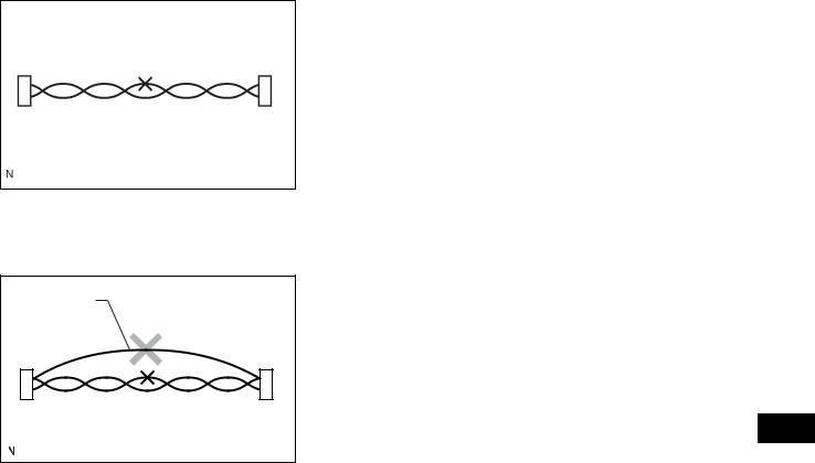
(a)After repairing the bus line with solder, wrap the repaired part with electrical tape.
NOTICE:
• The CANL bus line and CANH bus line must be installed together all the times.
When installing, make sure to twist them. CAN bus lines are likely to be influenced by electrical noise if they are not twisted.
• The difference in length between the CANL bus line and CANH bus line should be 100 mm (3.937 in.) or less.
•Leave approximately 80 mm (3.150 in.) loose in the twisted wires around the connector.
(b)Do not use bypass wiring between the connectors.
NOTICE:
The ability of the twisted bus lines to resist interference will be lost if bypass wiring is used.
PS

PS–6 |
POWER STEERING – ELECTRONIC POWER STEERING SYSTEM |
|
PARTS LOCATION
|
HYBRID VEHICLE CONTROL ECU |
|
POWER STEERING LINK |
|
- TORQUE SENSOR |
|
- POWER STEERING MOTOR |
|
- ROTATION ANGLE SENSOR |
|
POWER STEERING ECU |
|
COMBINATION METER |
|
- PS WARNING LIGHT |
|
SKID CONTROL ECU |
|
DLC3 |
PS |
MAIN BODY ECU (INSTRUMENT PANEL J/B) |
|
|
|
B150822E01 |
POWER STEERING – ELECTRONIC POWER STEERING SYSTEM |
PS–7 |
|
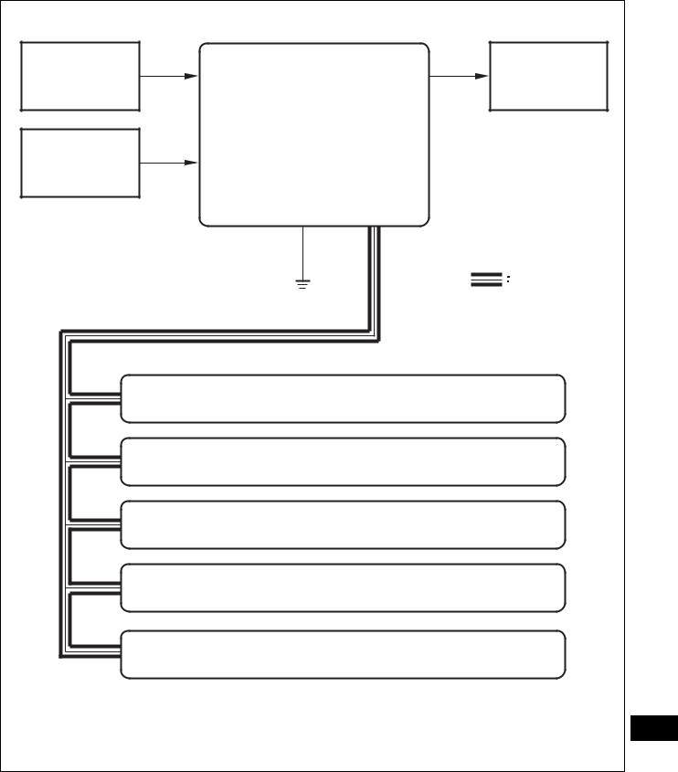
SYSTEM DIAGRAM
Motor Rotation |
EPS Motor |
Angle Sensor |
Power Steering ECU Assembly |
|
|
|
- Motor Relay |
|
- Power Source Relay |
|
- Motor Current Sensor |
Torque Sensor |
- Temperature Sensor |
|
|
|
CAN |
|
Skid Control ECU |
|
Steering Angle Sensor |
|
Hybrid Vehicle Control ECU |
|
Combination Meter |
|
Main Body ECU (Instrument Panel J/B) |
|
PS |
|
B139367E01 |
Transmitting ECU |
Receiving ECU |
Signals |
Communication method |
|
(transmitter) |
||||
|
|
|
||
|
|
|
|
|
Hybrid Vehicle Control ECU |
Power Steering ECU Assembly |
T/M variation information signal |
CAN |
|
|
|
|
|

PS–8 |
POWER STEERING – ELECTRONIC POWER STEERING SYSTEM |
|
Transmitting ECU |
Receiving ECU |
Signals |
Communication method |
|
(transmitter) |
||||
|
|
|
||
|
|
|
|
|
Hybrid Vehicle Control ECU |
Power Steering ECU Assembly |
Ready signal |
CAN |
|
|
|
|
|
|
Hybrid Vehicle Control ECU |
Power Steering ECU Assembly |
Ambient temperature signal |
CAN |
|
|
|
|
|
|
Hybrid Vehicle Control ECU |
Power Steering ECU Assembly |
Intake air temperature signal |
CAN |
|
|
|
|
|
|
Hybrid Vehicle Control ECU |
Power Steering ECU Assembly |
Engine variation information |
CAN |
|
signal |
||||
|
|
|
||
|
|
|
|
|
Hybrid Vehicle Control ECU |
Power Steering ECU Assembly |
Vehicle destination information |
CAN |
|
signal |
||||
|
|
|
||
|
|
|
|
|
Hybrid Vehicle Control ECU |
Power Steering ECU Assembly |
TC terminal condition |
CAN |
|
|
|
|
|
|
Skid Control ECU |
Power Steering ECU Assembly |
Output command value (to EPS) |
CAN |
|
signal |
||||
|
|
|
||
|
|
|
|
|
Skid Control ECU |
Power Steering ECU Assembly |
Additional torque target signal |
CAN |
|
|
|
|
|
|
Skid Control ECU |
Power Steering ECU Assembly |
Vehicle speed (SP1) status signal |
CAN |
|
|
|
|
|
|
Skid Control ECU |
Power Steering ECU Assembly |
Target steering angle signal |
CAN |
|
|
|
|
|
|
Skid Control ECU |
Power Steering ECU Assembly |
Target steering angle and |
CAN |
|
additional torque valid signal |
||||
|
|
|
||
|
|
|
|
|
Skid Control ECU |
Power Steering ECU Assembly |
Vehicle speed (SP1) signal |
CAN |
|
|
|
|
|
|
Skid Control ECU |
Power Steering ECU Assembly |
Test mode signal |
CAN |
|
|
|
|
|
|
Skid Control ECU |
Power Steering ECU Assembly |
VSC controlling signal |
CAN |
|
|
|
|
|
|
Skid Control ECU |
Power Steering ECU Assembly |
ABS controlling signal |
CAN |
|
|
|
|
|
|
Steering Angle Sensor |
Power Steering ECU Assembly |
Data continuity (valid/invalid) |
CAN |
|
signal |
||||
|
|
|
||
|
|
|
|
|
Steering Angle Sensor |
Power Steering ECU Assembly |
+B open circuit signal |
CAN |
|
|
|
|
|
|
Steering Angle Sensor |
Power Steering ECU Assembly |
Sensor malfunction signal |
CAN |
|
|
|
|
|
|
Steering Angle Sensor |
Power Steering ECU Assembly |
Steering angle signal |
CAN |
|
|
|
|
|
|
Steering Angle Sensor |
Power Steering ECU Assembly |
Zero point memory (in sensor) |
CAN |
|
valid/invalid signal |
||||
|
|
|
||
|
|
|
|
|
Steering Angle Sensor |
Power Steering ECU Assembly |
Zero point (stored in steering |
CAN |
|
angle sensor) signal |
||||
|
|
|
||
|
|
|
|
|
Main Body ECU |
Power Steering ECU Assembly |
Vehicle model signal |
CAN |
|
(Instrument Panel J/B) |
||||
|
|
|
||
|
|
|
|
|
Power Steering ECU Assembly |
Skid Control ECU |
EPS pinion angle invalid signal |
CAN |
|
|
|
|
|
|
Power Steering ECU Assembly |
Skid Control ECU |
EPS assisting current invalid |
CAN |
|
signal |
||||
|
|
|
||
|
|
|
|
|
Power Steering ECU Assembly |
Skid Control ECU |
EPS torque sensor value invalid |
CAN |
|
signal |
||||
|
|
|
||
|
|
|
|
|
Power Steering ECU Assembly |
Hybrid Vehicle Control ECU |
EPS idle up request signal |
CAN |
|
|
|
|
|
|
Power Steering ECU Assembly |
Skid Control ECU |
EPS torque sensor value signal |
CAN |
|
|
|
|
|
|
Power Steering ECU Assembly |
Skid Control ECU |
EPS pinion angle signal |
CAN |
|
|
|
|
|
|
Power Steering ECU Assembly |
Skid Control ECU |
EPS assisting current signal |
CAN |
|
|
|
|
|
|
Power Steering ECU Assembly |
Combination Meter |
EPS light ON request signal |
CAN |
|
|
|
|
|
|
Power Steering ECU Assembly |
Combination Meter |
EPS diagnostic information signal |
CAN |
|
|
|
|
|
PS

POWER STEERING – ELECTRONIC POWER STEERING SYSTEM |
PS–9 |
|
SYSTEM DESCRIPTION
1. |
DESCRIPTION |
|
|
(a) The EPS system generates assist torque to assist |
|
|
|
steering effort through the operation of the motor |
|
|
installed on the power steering link assembly. |
|
|
The direction and amount of power assistance are |
|
|
determined by signals from the torque sensor, and |
|
|
controlled in accordance with vehicle speed. As a |
|
|
result, steering effort is controlled to be light during |
|
|
low speed driving and moderately high during high |
|
|
speed driving. |
2. |
FUNCTIONS OF COMPONENTS |
|
|
|
|
Components |
|
Function |
|
|
|
|
|
Calculates degree of assistance needed based on steering torque and |
|
|
vehicle speed. Drives the motor based on motor electric angle |
Power Steering ECU Assembly |
|
obtained from the motor rotation angle sensor. |
|
|
|
|
Boosts battery voltage to generate motor drive voltage. |
|
|
|
|
|
|
|
|
|
Restricts power assistance to protect the system if the motor and ECU |
|
|
overheat. |
|
|
|
Torque Sensor |
|
Detects steering effort generated when the steering wheel is turned. |
|
|
|
Power Steering Motor |
|
Located coaxially with the rack shaft. Its rotation is converted to the |
|
rectilinear motion of the steering rack via the ball screw nut and ball. |
|
|
|
|
|
|
|
Hybrid Vehicle Control ECU |
|
Transmits ready signal to the power steering ECU. |
|
|
|
PS
PS–10 |
POWER STEERING – ELECTRONIC POWER STEERING SYSTEM |
|
3.OPERATION EXPLANATION
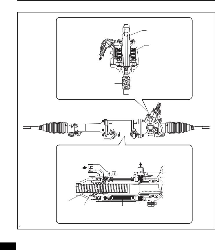
Torque Sensor Portion: |
|
|
|
Input Shaft |
Torsion Bar |
||
|
|
Torque Sensor |
|
To Power Steering ECU |
|
|
|
Assembly |
|
|
|
Output Shaft |
|
||
Power Steering Motor Portion: |
To Power Steering ECU |
||
Assembly |
|||
|
|
||
From Power |
|
|
|
Steering ECU |
|
|
|
Assembly |
|
Motor Rotation |
|
|
|
||
|
|
Angle Sensor |
|
Ball Screw |
|
|
|
Nut |
|
|
|
Ball |
|
|
|
Steering Rack |
Power Steering Motor |
||
|
|||
|
|
C106460E02 |
|
(a) The torque sensors is mounted on the input shaft to the main shaft and on the output shaft to the pinion shaft. The input and output shafts are joined by a
PS torsion bar.
(b) If the steering wheel is turned, the torsion bar twists, resulting in a difference in the rotation angle detected by the torque sensor. The power steering ECU assembly calculates torque based on this difference.
POWER STEERING – ELECTRONIC POWER STEERING SYSTEM |
PS–11 |
|
(c)The power steering ECU assembly calculates proper assisting torque, according to vehicle speed, based on the torque obtained in the previous step. Then the ECU controls the motor drive circuit in order to allow it to generate assisting torque.
(d)A ball screw nut is attached to the motor shaft. It converts the rotational motion of the motor into the rectilinear motion of the steering rack via the ball.
(e)The assisting force generated in the above process will reduce the steering effort required by the driver.
PS
PS–12 |
POWER STEERING – ELECTRONIC POWER STEERING SYSTEM |
|
HOW TO PROCEED WITH TROUBLESHOOTING
Perform troubleshooting according to the following flowchart. HINT:
• For further details, see the page given.
• *: Use the intelligent tester.
1 VEHICLE BROUGHT TO WORKSHOP
NEXT
2CUSTOMER PROBLEM ANALYSIS
NEXT
3CHECK DTC AND FREEZE FRAME DATA*
(a) Record the DTCs and freeze frame data.
NEXT
4CLEAR DTC AND FREEZE FRAME DATA*
NEXT
5PROBLEM SYMPTOM CONFIRMATION
SYMPTOM DOES NOT OCCUR (GO TO STEP 6)

 SYMPTOM OCCURS (GO TO STEP 7)
6SYMPTOM SIMULATION
NEXT
7CHECK DTC*
PS
(a)Recheck for DTCs. HINT:
•Refer to the diagnostic trouble code chart if any DTCs are output.
•If any CAN communication system DTCs are output, perform troubleshooting on the CAN communication system first (See page CA-7).
POWER STEERING – ELECTRONIC POWER STEERING SYSTEM |
PS–13 |
|
•If communication to the power steering ECU assembly is not established through the intelligent tester, inspect terminals SIL of the DLC3 and power steering ECU assembly, and inspect the IG circuit of the power steering ECU assembly.
NORMAL SYSTEM CODE IS OUTPUT: GO TO
STEP 8

 TROUBLE CODE IS OUTPUT: GO TO STEP 9
8PROBLEM SYMPTOMS TABLE
NEXT
9DTC CHART
NEXT
10CIRCUIT INSPECTION*
NEXT
11IDENTIFICATION OF PROBLEM
NEXT
12REPAIR OR REPLACE
NEXT
13 CONFIRMATION TEST
NEXT
END
PS
PS–14 |
POWER STEERING – ELECTRONIC POWER STEERING SYSTEM |
|
CALIBRATION
DLC3 |
Intelligent Tester |
C131977E01 |
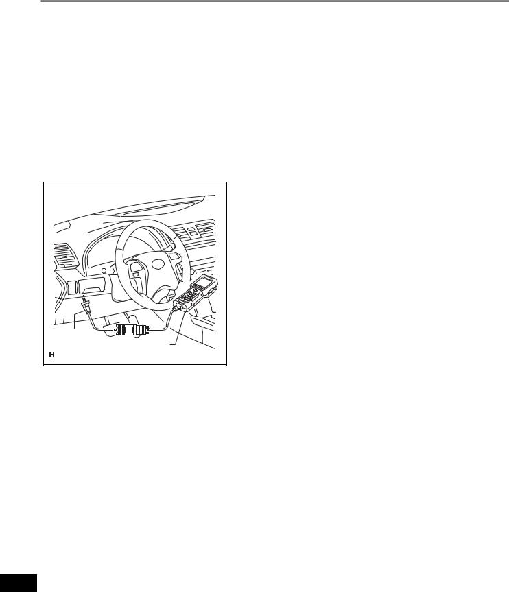
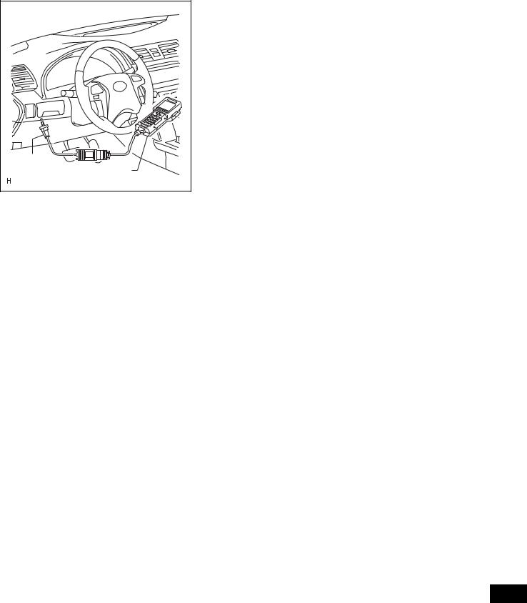
1.ROTATION ANGLE SENSOR VALUE INITIALIZATION AND TORQUE SENSOR ZERO POINT CALIBRATION NOTICE:
Clear the rotation angle sensor calibration value, initialize the rotation angle sensor value, and calibrate the torque sensor zero point if any of the following has occurred:
•The power steering ECU assembly has been replaced.
•The power steering link assembly has been replaced.
•Steering effort differs between left and right.
(a)Inspection before calibration
(1)Connect the intelligent tester (with CAN VIM) to the DLC3.
(2)Turn the power switch on (IG).
(3)Turn the intelligent tester on.
(4)Select "IG SUPPLY" from the data list.
(5)Check the IG power supply voltage on the tester screen.
Tester Display |
Measurement Item/Range |
Inspection Condition |
Reference Value |
|
|
|
|
|
|
IG SUPPLY |
ECU power source voltage/ |
Power switch on (IG) |
10 to 14 V |
|
Min.: 0 V, Max.: 25.5 V |
||||
|
|
|
||
|
|
|
|
Standard voltage: 10 to 14 V
NOTICE:
If the IG power supply voltage is 10 V or less, calibration cannot be performed. In this case, charge or replace the battery, and then perform calibration.
PS
POWER STEERING – ELECTRONIC POWER STEERING SYSTEM |
PS–15 |
|
|
|
|
(b) Rotation angle sensor calibration value clear, |
|
|
|
rotation angle sensor value initialization, and torque |
|
|
|
sensor zero point calibration. |
|
|
|
NOTICE: |
|
|
|
• If DTC C1516 (Torque Sensor Zero Point |
|
|
|
Adjustment Incomplete) is stored, the torque |
|
|
|
sensor zero point cannot be calibrated. Clear |
|
|
|
the DTC before starting calibration. |
|
|
|
• If DTC C1526 (Rotation Angle Sensor |
|
|
|
Initialization Incomplete) is stored, the |
|
|
|
rotation angle sensor value cannot be |
|
|
|
initialized. Clear the DTC before starting |
DLC3 |
|
|
initialization. |
Intelligent Tester |
|
(1) Connect the intelligent tester (with CAN VIM) to |
|
|
|
the DLC3. |
|
|
|
C131977E01 |
|
|
|
(2) Turn the power switch on (IG). |
|
|
|
|
|
|
|
|
(3) Turn the intelligent tester on. |
|
|
|
(4) Select "TRQ SENSOR ADJ". |
|
|
|
(5) Follow the procedures on the tester display to |
|
|
|
clear the rotation angle sensor calibration value, |
|
|
|
initialize the rotation angle sensor value, and |
|
|
|
calibrate the torque sensor zero point. |
|
|
|
NOTICE: |
|
|
|
• When initializing the rotation angle sensor |
|
|
|
value, observe the following to stabilize |
|
|
|
sensor voltage: |
|
|
|
After turning the power switch on (IG), |
|
|
|
wait for at least 2.5 seconds before |
|
|
|
turning the steering wheel. Do not turn the |
|
|
|
steering wheel quickly. |
|
|
|
• The steering wheel will vibrate during |
|
|
|
torque sensor zero point calibration. Do |
|
|
|
not touch the steering wheel while it is |
|
|
|
vibrating or for 2 seconds after it stops. |
PS

PS–16 |
POWER STEERING – ELECTRONIC POWER STEERING SYSTEM |
|
PROBLEM SYMPTOMS TABLE
ELECTRONIC POWER STEERING SYSTEM
Symptom |
|
Suspected Area |
See page |
|
|
|
|
|
|
|
1. |
Front tires (Improperly inflated, unevenly worn) |
TW-3 |
|
|
|
|
|
|
|
2. |
Front wheel alignment (Incorrect) |
SP-4 |
|
|
|
|
|
|
|
3. |
Front suspension |
SP-24 |
|
|
|
|
|
|
|
4. |
Power steering link assembly |
PS-61 |
|
|
|
|
|
|
Steering is heavy. |
5. |
Steering column assembly |
SR-35 |
|
|
|
|
||
6. |
Battery and power source system |
- |
||
|
||||
|
|
|
|
|
|
7. |
Power source voltage of power steering ECU assembly |
PS-50 |
|
|
|
|
|
|
|
8. |
Power steering ECU assembly |
PS-68 |
|
|
|
|
|
|
|
9. |
Vehicle condition (The steering wheel is turned from left to |
- |
|
|
right repeatedly with the vehicles stopped or a heavy load is |
|
||
|
continuously applied to the vehicle) |
|
||
|
|
|
|
|
|
1. |
Power steering ECU assembly (Steering center point is not |
PS-13 |
|
|
recorded correctly) |
|
||
|
|
|
|
|
|
2. |
Front tires (Improperly inflated, unevenly worn) |
TW-3 |
|
|
|
|
|
|
Steering effort differs between right and left, or is |
3. |
Front wheel alignment (Incorrect) |
SP-4 |
|
|
|
|
||
uneven. |
4. Front suspension |
SP-24 |
||
|
|
|
|
|
|
5. |
Power steering link assembly |
PS-61 |
|
|
|
|
|
|
|
6. |
Steering column assembly |
SR-35 |
|
|
|
|
|
|
|
7. |
Power steering ECU assembly |
PS-68 |
|
|
|
|
|
|
|
1. |
Speed sensor |
BC-273 |
|
While driving, steering effort does not change in |
|
|
|
|
2. |
Skid control ECU |
BC-289 |
||
accordance with vehicle speed, or the steering wheel |
||||
|
|
|
||
3. |
Power steering link assembly |
PS-61 |
||
does not return to its centered position easily. |
||||
|
|
|
||
|
4. |
Power steering ECU assembly |
PS-68 |
|
|
|
|
||
Friction sounds occur when turning the steering wheel |
1. Power steering link assembly |
PS-61 |
||
during low speed driving. |
2. Power steering ECU assembly |
PS-68 |
||
|
|
|
||
High-pitched sounds (squeaking) occur when turning |
Power steering link assembly |
PS-61 |
||
the steering wheel slowly with the vehicle stopped. |
|
|
|
|
|
|
|
||
The steering wheel vibrates and noise occurs when |
1. Power steering link assembly |
PS-61 |
||
turning the steering wheel with the vehicle stopped. |
2. Steering column assembly |
PS-68 |
||
|
|
|
||
PS warning light remains on. |
PS warning light remains on |
PS-50 |
||
|
|
|
||
PS warning light does not come on. |
PS warning light does not come on |
PS-54 |
||
|
|
|
|
|
PS

POWER STEERING – ELECTRONIC POWER STEERING SYSTEM |
PS–17 |
|
TERMINALS OF ECU
1.TERMINALS OF ECU
A66 |
A68 |
A67 |
|
|
C116647E02 |
HINT:
The power steering ECU assembly uses waterproof connectors. Therefore, voltage or waveforms cannot be checked with the connectors connected to the vehicle.
Terminal No. (Symbols) |
Wiring Color |
Terminal Description |
|
|
|
A66-2 (CANH) |
B |
High-level CAN bus line |
|
|
|
A66-3 (CANL) |
W |
Low-level CAN bus line |
|
|
|
A66-4 (PIG) |
W |
Power source |
|
|
|
A66-5 (PGND) |
B |
Power ground |
|
|
|
A66-9 (IG) |
O |
IG power source |
|
|
|
A67-1 (RZG) |
W |
Rotation angle sensor power source circuit ground |
|
|
|
A67-2 (SRZG) |
BR |
Rotation angle sensor shield ground |
|
|
|
A67-3 (RZV) |
G |
Rotation angle sensor power source |
|
|
|
A67-4 (TRQV) |
P |
Torque sensor power source |
|
|
|
A67-6 (TQG1) |
L |
Torque sensor power source circuit ground |
|
|
|
A67-7 (RZSN) |
B |
SIN phase input signal (Rotation angle sensor) |
|
|
|
A67-8 (RZCS) |
R |
COS phase input signal (Rotation angle sensor) |
|
|
|
A67-9 (INSN) |
B |
SIN phase input signal (Torque sensor input shaft side) |
|
|
|
A67-10 (INCS) |
R |
COS phase input signal (Torque sensor input shaft side) |
|
|
|
A67-11 (OUSN) |
W |
SIN phase input signal (Torque sensor output shaft side) |
|
|
|
A67-12 (OUCS) |
G |
COS phase input signal (Torque sensor output shaft side) |
|
|
|
A67-13 (TQG2) |
Y |
Torque sensor detection circuit ground |
|
|
|
A68-1 (V) |
R |
V phase motor output |
|
|
|
A68-2 (U) |
B |
U phase motor output |
|
|
|
A68-3 (W) |
W |
W phase motor output |
|
|
|
2.INSPECT WIRE HARNESS SIDE CONNECTOR
A66 |
A68 |
A67 |
|
||
|
|
PS |
|
|
C116648E02 |
PS–18 |
POWER STEERING – ELECTRONIC POWER STEERING SYSTEM |
|
Terminal No. (Symbols) |
|
Wiring Color |
Terminal Description |
Condition |
Specified Condition |
|
|
|
|
|
|
A66-4 (PIG) - A66-5 (PGND) |
W - B |
Power source |
Always |
10 to 14 V |
|
|
|
|
|
|
|
A66-5 (PGND) - Body ground |
B - Body ground |
Power ground |
Always |
Below 1 Ω |
|
|
|
|
|
|
|
A66-9 (IG) - A66-5 (PGND) |
O - B |
IG power source |
Power switch on (IG) |
10 to 14 V |
|
|
|
|
|
|
|
A68-2 (U) - A68-3 (W)/A68-1 |
(V) |
B - W/R |
U phase motor output |
Always |
Below 1 Ω |
|
|
|
|
|
|
A68-3 (W) - A68-2 (U)/A68-1 |
(V) |
W - BR |
W phase motor output |
Always |
Below 1 Ω |
|
|
|
|
|
|
A68-1 (V) - A68-2 (U)/ A68-3 (W) |
R - B/W |
V phase motor output |
Always |
Below 1 Ω |
|
|
|
|
|
|
|
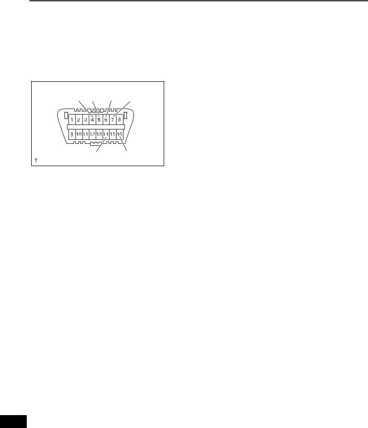
CG |
SG CANH |
SIL |
|
CANL |
BAT |
|
|
H100769E16 |
DIAGNOSIS SYSTEM
1.CHECK DLC3
(a)The vehicle's ECU uses ISO 15765-4 for communication protocol. The terminal arrangement of the DLC3 complies with SAE J1962 and matches the ISO 15765-4 format.
Symbols (Terminal No.) |
Terminal Description |
Condition |
Specified Condition |
|
|
|
|
SIL (7) - SG (5) |
Bus "+" line |
During transmission |
Pulse generation |
|
|
|
|
CG (4) - Body ground |
Chassis ground |
Always |
Below 1 Ω |
|
|
|
|
SG (5) - Body ground |
Signal ground |
Always |
Below 1 Ω |
|
|
|
|
BAT (16) - Body ground |
Battery positive |
Always |
10 to 14 V |
|
|
|
|
CANH (6) - CANL (14) |
CAN bus line |
Power switch off* |
54 to 69 Ω |
CANH (6) - CG (4) |
HIGH-level CAN bus line |
Power switch off* |
200 Ω or higher |
CANL (14) - CG (4) |
LOW-level CAN bus line |
Power switch off* |
200 Ω or higher |
CANH (6) - BAT (16) |
HIGH-level CAN bus line |
Power switch off* |
6 kΩ or higher |
CANL (14) - BAT (16) |
LOW-level CAN bus line |
Power switch off* |
6 kΩ or higher |
NOTICE:
*: Before measuring the resistance, leave the vehicle as is for at least 1 minute and do not operate the power switch, any other switches or the doors.
If the result is not as specified, the DLC3 may have a malfunction. Repair or replace the harness and connector.
PS

POWER STEERING – ELECTRONIC POWER STEERING SYSTEM |
PS–19 |
|
DLC3 |
Intelligent Tester |
C131977E01 |
B150816 |
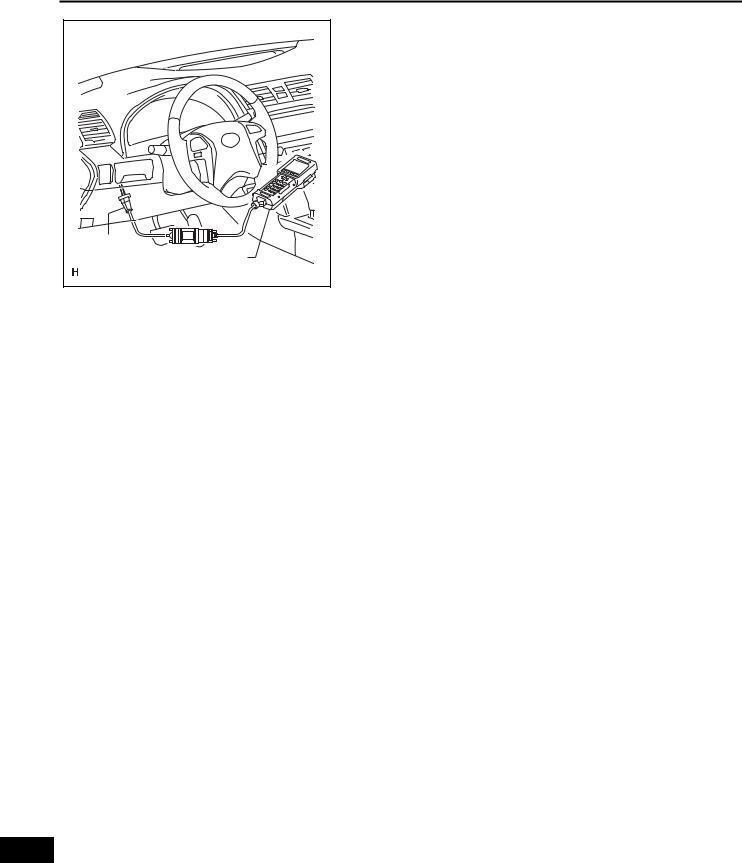
(b)Connect the cable of the intelligent tester (with CAN VIM) to the DLC3, turn the power switch on (IG) and attempt to use the intelligent tester. If the screen displays a communication error message, a problem exists in the vehicle side or tester side. HINT:
•If communication is normal when the tool is connected to another vehicle, inspect the DLC3 on the original vehicle.
•If communication is still impossible when the tool is connected to another vehicle, the problem is probably in the tool itself. Consult the Service Department listed in the tool's instruction manual.
2.P/S WARNING LIGHT
(a)Check that the PS warning light comes on when the power switch is turned on (IG) and goes off in approximately 3 seconds.
If the warning light does not come on or remains on, inspect the PS warning light circuit.
Trouble Area |
See Procedure |
|
|
|
|
PS warning light circuit (Remains on) |
PS-50 |
|
|
|
|
PS warning light circuit (Does not come |
PS-54 |
|
on) |
||
|
||
|
|
DTC CHECK / CLEAR
1. CHECK FOR DTCs
(a) Connect the intelligent tester (with CAN VIM) to the DLC3.
(b) Turn the power switch on (IG).
(c) Turn the intelligent tester on.
(d) Read the DTCs by following the display on the intelligent tester.
HINT:
Refer to the intelligent tester operator's manual for further details.
DLC3
Intelligent Tester
C131977E01
PS
PS–20 |
POWER STEERING – ELECTRONIC POWER STEERING SYSTEM |
|
2. |
CLEAR DTCs |
|
(a) Connect the intelligent tester (with CAN VIM) to the |
|
DLC3. |
|
(b) Turn the power switch on (IG). |
|
(c) Turn the intelligent tester on. |
|
(d) Clear the DTCs by following the display on the |
|
intelligent tester. |
|
HINT: |
|
Refer to the intelligent tester operator's manual for |
|
further details. |
DLC3 |
|
Intelligent Tester |
|
C131977E01 |
|
PS
POWER STEERING – ELECTRONIC POWER STEERING SYSTEM |
PS–21 |
|
FREEZE FRAME DATA
DLC3 |
Intelligent Tester |
C131977E01 |
1.FREEZE FRAME DATA NOTICE:
•It is difficult to show the specified values (judgement values) clearly because freeze frame data values change significantly due to differences in measurement conditions, surroundings, or vehicle conditions. For this reason, there may be a problem even when the values are within specifications.
•Turn the power switch on (IG) and park the vehicle on level ground. Check the freeze frame data by using the intelligent tester.
(a)Connect the intelligent tester (with CAN VIM) to the DLC3.
(b)Turn the power switch on (IG) and check the freeze frame data by following the prompts on the intelligent tester's display screen.
Tester Display |
Item Description/Range |
Inspection Condition |
|
Reference Value |
|
|
|
|
|
|
|
|
|
|
Vehicle speed from meter/ |
1. Vehicle is stopped |
1. |
0 km/h (0 mph) |
|
|
SPD |
Min.: 0 km/h (0 mph), Max.: 300 |
2. Vehicle is driven at a constant |
|
|
||
2. |
No significant fluctuation |
|
|
|||
|
km/h (186 mph) |
speed |
|
|
||
|
|
|
|
|
||
|
|
|
|
|
|
|
ENGINE REV |
Engine revolution/ |
Engine is running at a constant |
No significant fluctuation |
|
|
|
Min.: 0 rpm, Max.: 12.800 rpm |
speed |
|
|
|||
|
|
|
|
|
||
|
|
|
|
|
|
|
MOTOR ACTUAL |
Amount of current to motor/ |
Power steering is in operation |
Value changes in proportion to |
|
|
|
Min.: -128 A, Max.: 127 A |
steering effort |
|
|
|||
|
|
|
|
|||
|
|
|
|
|
|
|
|
Demanded amount of current to |
|
Value changes in proportion to |
|
|
|
COMMAND VALUE |
motor/ |
Power steering is in operation |
|
|
||
steering effort |
|
|
||||
|
Min.: -128 A, Max.: 127 A |
|
|
|
||
|
|
|
|
|
|
|
|
|
|
|
|
|
|
|
Steering angle speed/ |
|
Value changes in proportion to |
|
|
|
STR ANGL VEL |
Min.: -4.096 deg/sec, Max.: 4.064 |
Steering wheel is turned |
|
|
||
steering speed |
|
|
||||
|
deg/sec |
|
|
|
||
|
|
|
|
|
|
|
|
|
|
|
|
|
|
THERMISTOR TEMP |
ECU substrate temperature/ |
Power switch on (IG) |
|
- |
|
|
Min.: -50°C, Max.: 205°C |
|
|
|
|||
|
|
|
|
|
|
|
|
|
|
|
|
|
|
|
Power source voltage to activate |
|
|
|
|
|
PIG SUPPLY |
motor/ |
Power steering is in operation |
10 to 14 V |
|
|
|
|
Min.: 0 V, Max.: 25.5 V |
|
|
|
|
|
|
|
|
|
|
|
PS |
IG SUPPLY |
ECU power source voltage/ |
Power switch on (IG) |
10 to 14 V |
|
||
Min.: 0 V, Max.: 25.5 V |
|
|||||
|
|
|
|
|
|
|
|
|
|
|
|
|
|
|
Steering angle sensor signal |
|
|
|
|
|
STR SENS SIG |
status/ |
- |
|
- |
|
|
|
OK or NG |
|
|
|
|
|
|
|
|
|
|
|
|
TRQ1 |
Torque sensor 1 rotation angle/ |
Steering wheel is turned |
Value changes from 0 to 360° |
|
|
|
Min.: 0 deg, Max.: 360 deg |
every 22.5° of steering angle |
|
|
|||
|
|
|
|
|||
|
|
|
|
|
|
|

PS–22 |
POWER STEERING – ELECTRONIC POWER STEERING SYSTEM |
|
Tester Display |
Item Description/Range |
Inspection Condition |
Reference Value |
|
|
|
|
|
|
TRQ2 |
Torque sensor 2 rotation angle/ |
Steering wheel is turned |
Value changes from 0 to 360° |
|
Min.: 0 deg, Max.: 360 deg |
every 22.5° of steering angle |
|||
|
|
|||
|
|
|
|
|
|
Zero point value of torque sensor |
Steering wheel is not turned |
Values differ depending on |
|
TRQ1 ZERO VAL |
1/ |
|||
(without load) |
vehicle |
|||
|
Min.: 0 deg, Max.: 360 deg |
|||
|
|
|
||
|
|
|
|
|
|
Zero point value of torque sensor |
Steering wheel is not turned |
Values differ depending on |
|
TRQ2 ZERO VAL |
2/ |
|||
(without load) |
vehicle |
|||
|
Min.: 0 deg, Max.: 360 deg |
|||
|
|
|
||
|
|
|
|
|
STEERING TORQU |
Steering torque/ |
Steering wheel is turned |
Value changes in proportion to |
|
Min.: -7.0 N*m, Max.: 7.0 N*m |
steering effort |
|||
|
|
|||
|
|
|
|
|
MOTOR ROTATE |
Motor rotation angle/ |
Steering wheel is turned |
Value changes from 0 to 360° |
|
Min.: 0 deg, Max.: 360 deg |
every 5° of steering angle |
|||
|
|
|||
|
|
|
|
|
|
Demanded amount of current to |
|
|
|
COMMAND VALUE 2 |
motor 2/ |
- |
- |
|
|
Min.: -128 A, Max.: 127 A |
|
|
|
|
|
|
|
|
PIG2 VOLTAGE |
Motor drive voltage/ |
Power steering is in operation |
27 to 34 V |
|
Min.: 0 V, Max.: 64 V |
||||
|
|
|
||
|
|
|
|
|
MOTOR VOLTAGE |
Motor power source voltage/ |
Power steering is in operation |
27 to 34 V |
|
Min.: 0 V, Max.: 64 V |
||||
|
|
|
||
|
|
|
|
|
MTR TERMINAL (U) |
Motor terminal voltage (U phase)/ |
Power steering is in operation |
0 to 34 V |
|
Min.: 0 V, Max.: 64 V |
||||
|
|
|
||
|
|
|
|
|
MTR TERMINAL (V) |
Motor terminal voltage (V phase)/ |
Power steering is in operation |
0 to 34 V |
|
Min.: 0 V, Max.: 64V |
||||
|
|
|
||
|
|
|
|
|
MTR TERMINAL (W) |
Motor terminal voltage (W phase)/ |
Power steering is in operation |
0 to 34 V |
|
|
Min.: 0 V, Max.: 64 V |
|
|
|
|
Number of times IG switch is |
|
|
|
IG ON/OFF TIMES |
turned on after DTC detection/ |
- |
- |
|
|
Min.: 0 time, Max.: 255 times |
|
|
|
|
|
|
|
|
|
Continuous overheat prevention |
|
|
|
MTR OVERHEAT |
control record/ |
- |
- |
|
|
REC or UNREC |
|
|
|
|
|
|
|
|
|
PIG power source voltage drop |
|
|
|
MTR LOW POWER |
record/ |
- |
- |
|
|
REC or UNREC |
|
|
|
|
|
|
|
|
|
Record of power revolution signal |
|
|
|
ENG REV INTER |
interruption/ |
- |
- |
|
|
REC or UNREC |
|
|
|
|
|
|
|
|
|
Record of steering angle sensor |
|
|
|
STR ANGL INTER |
signal interruption/ |
- |
- |
|
|
REC or UNREC |
|
|
|
|
|
|
|
|
|
Record of vehicle speed signal |
|
|
|
SPD SIG INVALID |
invalid/ |
- |
- |
|
|
REC or UNREC |
|
|
|
|
|
|
|
|
BATTERY VOLTAGE |
Battery voltage/ |
- |
10 to 14 V |
|
Min.: 0 V, Max.: 25.5 V |
||||
|
|
|
||
|
|
|
|
|
PS ASSIST SIG |
Power steering assist signal/ |
Power switch on (IG) |
- |
|
ON or OFF |
||||
|
|
|
||
|
|
|
|
|
|
Number of detected DTCs when |
|
|
|
# CODES |
freeze frame data is stored/ |
- |
- |
|
|
Min.: 0, Max.: 255 |
|
|
|
|
|
|
|
PS

POWER STEERING – ELECTRONIC POWER STEERING SYSTEM |
PS–23 |
|
FAIL-SAFE CHART
If a problem occurs in the electronic power steering system, the PS warning light will come on in the combination meter and steering power assistance will be stopped, fixed at a particular point, or decreased simultaneously to protect the system.
DTC No. |
Malfunction |
Fail-safe |
|
|
|
|
|
C1511 |
|
|
|
|
|
|
|
C1512 |
Torque Sensor Circuit Malfunction |
|
|
|
|
|
|
C1513 |
|
|
|
|
|
|
|
C1521 |
|
|
|
|
|
|
|
C1522 |
Motor Circuit Malfunction |
|
|
|
Power assistance stops. |
||
C1523 |
|||
|
|||
|
|
|
|
C1524 |
|
|
|
|
|
|
|
C1528 |
Motor Rotation Angle Sensor Malfunction |
|
|
|
|
|
|
C1531 |
ECU Malfunction |
|
|
|
|
||
C1532 |
|
||
|
|
||
|
|
|
|
C1555 |
Motor Relay Welding Failure |
|
|
|
|
|
|
|
|
System overheat prevention control continues |
|
C1533 |
ECU Malfunction |
without using the substrate temperature |
|
|
|
sensor. |
|
|
|
|
|
|
|
Torque sensor zero point and rotation angle |
|
C1534 |
ECU Malfunction |
sensor calibration value are set to the default |
|
|
|
values. |
|
|
|
|
|
C1541 |
Vehicle Speed Signal Malfunction |
Amount of power assistance is fixed for a |
|
U0129 |
Lost Communication With Skid Control ECU |
speed of 100 km/h (62 mph). |
|
|
|
|
HINT:
The amount of power assistance may be decreased to prevent the motor and ECUs from overheating if the steering wheel is continuously turned when the vehicle is either stopped or driven at a low speed, or if the steering wheel is kept at either full lock position for a long time. In that case, the amount of power assistance will return to normal if the steering wheel is not turned for approximately 10 minutes with the engine idling.
PS

PS–24 |
POWER STEERING – ELECTRONIC POWER STEERING SYSTEM |
|
DLC3 |
Intelligent Tester |
C131977E01 |
DATA LIST / ACTIVE TEST
1.DATA LIST
HINT:
By accessing the data list displayed on the intelligent tester, values of switches, sensors and other related parts can be checked without removing any parts.
Reading the data list is the first step in troubleshooting and is one method to shorten labor time.
(a)Connect the intelligent tester (with CAN VIM) to the DLC3.
(b)Turn the power switch on (IG).
(c)Operate the intelligent tester according to the steps on the display and select the data list.
|
|
Tester Display |
Measurement Item/Range |
Normal Condition |
|
Reference Value |
|
|
|
|
|
|
|
|
|
|
Vehicle speed from meter/ |
1. Vehicle is stopped |
1. |
0 km/h (0 mph) |
|
|
SPD |
Min.: 0 km/h (0 mph), Max.: 300 |
2. Vehicle is driven at a constant |
||
|
|
2. |
No significant fluctuation |
|||
|
|
|
km/h (186 mph) |
speed |
||
|
|
|
|
|
||
|
|
|
|
|
|
|
|
|
ENGINE REV |
Engine revolution/ |
Engine is running at a constant |
No significant fluctuation |
|
|
|
Min.: 0 rpm, Max.: 12.800 rpm |
speed |
|||
|
|
|
|
|
||
|
|
|
|
|
|
|
|
|
MOTOR ACTUAL |
Amount of current to motor/ |
Power steering is in operation |
Value changes in proportion to |
|
|
|
Min.: -128 A, Max.: 127 A |
steering effort |
|||
|
|
|
|
|||
|
|
|
|
|
|
|
|
|
|
Demanded amount of current to |
|
Value changes in proportion to |
|
|
|
COMMAND VALUE |
motor/ |
Power steering is in operation |
||
|
|
steering effort |
||||
|
|
|
Min.: -128 A, Max.: 127 A |
|
||
|
|
|
|
|
|
|
|
|
|
|
|
|
|
|
|
|
Steering angle speed/ |
|
Value changes in proportion to |
|
|
|
STR ANGL VEL |
Min.: -4.096 deg/sec, Max.: 4.064 |
Steering wheel is turned |
||
|
|
steering speed |
||||
|
|
|
deg/sec |
|
||
|
|
|
|
|
|
|
|
|
|
|
|
|
|
|
|
THERMISTOR TEMP |
ECU substrate temperature/ |
Power switch on (IG) |
|
- |
|
|
Min.: -50°C, Max.: 205°C |
|
|||
|
|
|
|
|
|
|
|
|
|
|
|
|
|
|
|
|
Power source voltage to activate |
|
|
|
|
|
PIG SUPPLY |
motor/ |
Power steering is in operation |
10 to 14 V |
|
|
|
|
Min.: 0 V, Max.: 25.5 V |
|
|
|
|
|
|
|
|
|
|
|
|
IG SUPPLY |
ECU power source voltage/ |
Power switch on (IG) |
10 to 14 V |
|
|
|
Min.: 0 V, Max.: 25.5 V |
||||
|
|
|
|
|
|
|
|
|
|
|
|
|
|
|
|
|
Steering angle sensor signal |
|
|
|
|
|
STR SENS SIG |
status/ |
- |
|
- |
|
|
|
OK or NG |
|
|
|
|
|
|
|
|
|
|
|
|
|
Torque sensor 1 rotation angle/ |
|
Value changes from 0 to 360° |
|
PS |
|
TRQ1 |
Steering wheel is turned |
|||
|
Min.: 0 deg, Max.: 360 deg |
every 22.5° of steering angle |
||||
|
|
|||||
|
|
|
|
|||
|
|
|
|
|
|
|
|
|
TRQ2 |
Torque sensor 2 rotation angle/ |
Steering wheel is turned |
Value changes from 0 to 360° |
|
|
|
Min.: 0 deg, Max.: 360 deg |
every 22.5° of steering angle |
|||
|
|
|
|
|||
|
|
|
|
|
|
|
|
|
|
Zero point value of torque sensor |
Steering wheel is not turned |
Values differ depending on |
|
|
|
TRQ1 ZERO VAL |
1/ |
|||
|
|
(without load) |
vehicle |
|||
|
|
|
Min.: 0 deg, Max.: 360 deg |
|||
|
|
|
|
|
|
|
|
|
|
|
|
|
|
 Loading...