


2GR-FE STARTING – STARTING SYSTEM |
ST–1 |
|
STARTING SYSTEM
PARTS LOCATION
ECM
STARTER
TRANSMISSION
CONTROL ECU
PARK/NEUTRAL
POSITION SWITCH
MAIN BODY ECU
INSTRUMENT PANEL J/B
-IGN FUSE
ENGINE ROOM R/B -STARTER RELAY -IGNITION RELAY -STARTER CUT RELAY -IG2 FUSE
-AM2 FUSE -ST/AM2 FUSE -ALT FUSE
with SMART KEY SYSTEM: |
|
-ENGINE SWITCH |
ST |
without SMART KEY SYSTEM: |
|
-AM1 FUSE |
-IGNITION SWITCH |
A135519E01

ST–2 |
2GR-FE STARTING – STARTING SYSTEM |
|
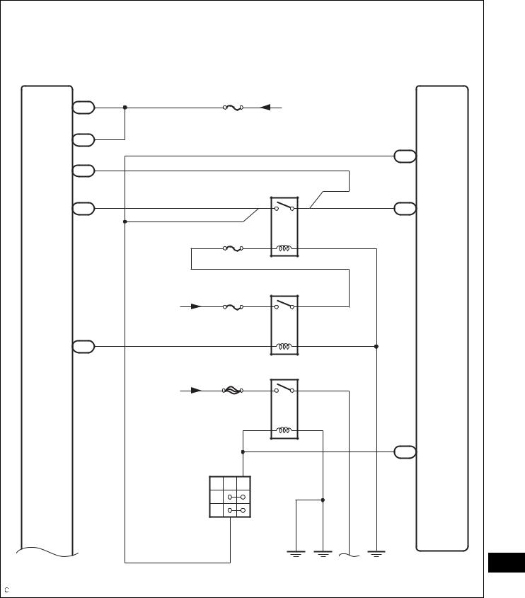
SYSTEM DIAGRAM
|
without Smart Key System: |
|
|
|
|
|
|
|
Transmission Control ECU |
|
|
|
|
ECM |
|
|
|
11 |
|
|
|
62 |
|
|
|
NSW C56 |
|
|
|
C55 NSW |
|
|
|
|
C1 |
|
4 |
|
|
|
|
|
L |
B |
|
|
|
|
|
|
Park/Neutral |
P |
|
|
|
|
|
|
Position Switch |
N |
|
|
|
|
|
|
|
9 |
|
|
|
|
|
10 |
|
|
|
48 |
|
|
|
STA C56 |
|
|
|
A55 |
STA |
|
|
E23 Ignition Switch |
|
|
|
|
|
|
|
|
ACC |
|
|
|
|
|
|
AM1 |
IG1 |
|
|
|
|
|
|
4 |
ST1 |
|
|
|
|
|
|
|
|
|
ST |
|
|
|
AM1 |
AM2 |
IG2 3 |
|
|
|
|
|
|
|
|
|
|||
|
|
5 |
|
|
1 |
2 |
|
|
|
|
ST2 |
|
|
|
|
|
|
|
7 |
|
5 |
3 |
|
|
ALT |
ST/AM2 |
|
|
|
|
|
|
|
|
Starter |
|
|
|
|
|
FL MAIN |
|
1 |
|
1 |
|
|
|
|
|
D1 |
|
C3 |
|
|
ST |
Battery |
|
|
M |
|
|
|
|
|
|
|
|
|
||
|
|
|
|
|
|
|
|
|
|
|
|
|
|
|
A135061E01 |
2GR-FE STARTING – STARTING SYSTEM |
ST–3 |
|
with Smart Key System: |
|
|
|
|
|
Main Body ECU |
|
|
|
ECM |
|
AM1 |
6 |
AM2 |
From Battery |
|
|
E7 |
|
|
|
||
AM2 |
1 |
|
|
|
|
E6 |
|
|
|
62 |
|
|
|
|
|
|
|
STR2 |
6 |
|
|
|
C55 NSW |
E9 |
|
|
|
|
|
|
8 |
|
ST CUT |
63 |
|
|
|
|
|
||
STR |
E7 |
|
5 |
3 |
C55 STAR |
|
|
|
|
||
|
|
IGN |
|
|
|
|
|
|
2 |
1 |
|
|
From |
IG2 |
|
IG2 |
|
|
|
|
|
||
|
|
|
|
|
|
|
Battery |
|
5 |
3 |
|
|
11 |
|
|
|
|
IG2D |
E6 |
|
1 |
2 |
|
|
|
|
|
||
|
From |
ST/AM2 |
ST |
|
|
|
|
|
|||
|
|
|
|
|
|
|
Battery |
|
5 |
3 |
|
|
|
|
1 |
2 |
48 |
|
|
|
|
|
A55 STA |
|
C1 |
9 |
|
|
|
|
B |
L |
|
|
|
|
Park/Neutral |
P |
|
|
|
|
Position Switch |
|
|
|
|
|
N |
|
|
|
|
|
|
4 |
|
|
|
|
|
|
|
|
ST |
|
|
|
|
|
A135062E01 |

ST–4 |
2GR-FE STARTING – STARTING SYSTEM |
|
17 SSW1 E7
16 SSW2 E7
|
2 |
7 |
|
E52 |
|
SS2 |
SS1 |
|
|
|
|
|
|
Engine Switch |
|
|
|
|
|
|
SS2 |
GND SS1 |
|
|
Free
Full
Traveling
GND 5
|
Starter |
1 |
1 |
D1 |
C3 |
Battery
A135063E01
ST

2GR-FE STARTING – SMART KEY SYSTEM |
ST–5 |
|
SMART KEY SYSTEM
PRECAUTION
1.EMERGENCY ENGINE START CONTROL
(a)If there is a malfunction in the stop light switch or STOP fuse, their signals may not be correctly transmitted to the main body ECU. This may result in the engine not starting even if the engine switch is pressed while the brake pedal is depressed and the shift lever is in the P position.
To activate the starter:
(1)Turn the engine switch from off to on (ACC).
(2)Press and hold the engine switch for 15 seconds.
2.PRECAUTIONS FOR PUSH-BUTTON START FUNCTION:
(a)Before starting the engine, firmly depress the brake pedal until the indicator in the engine switch turns green.
(b)The power source mode (off, on (ACC), on (IG)) is always retained in memory by the vehicle. If the battery is disconnected, the power source mode that was present before disconnection will be restored after the battery is reconnected. Be sure to turn the engine switch off before disconnecting the cable from the negative battery terminal. Be careful if the power source mode of a vehicle with a discharged battery is not known.
(c)After the battery is reconnected, be sure to wait 10 seconds or more before attempting to start the engine. The engine may not start immediately after the battery is reconnected.
(d)If the electrical key is held near the engine switch to start the engine when the electrical key battery is depleted, the following warnings will sound:
(1)Driver's door open → closed
•An exit warning will sound if the shift lever is in a position other than P and the power source is in a mode other than off.
•An exit warning will sound if the shift lever is in the P position and the power source is in a mode other than off.
(2)Doors other than the driver door open → closed
•A warning will sound to indicate that the
electrical key has been taken out of the
vehicle. ST These warnings will sound because it is not possible for the
vehicle to determine if the key is present in the vehicle (due to the depleted key battery). These warnings do not indicate system malfunctions.

ST–6 |
2GR-FE STARTING – SMART KEY SYSTEM |
|
PARTS LOCATION
|
|
PARK / NEUTRAL |
|
ECM (2GR-FE) |
POSITION SWITCH |
|
|
|
|
ENGINE ROOM J/B AND R/B |
|
|
- AM2 FUSE |
- ST / AM2 FUSE |
|
WIRELESS BUZZER |
- ECU-B NO. 1 FUSE |
|
- IG2 FUSE |
|
|
- IG2 RELAY |
- ST CUT RELAY |
|
- ST RELAY |
|
|
ELECTRICAL KEY OSCILLATOR |
|
|
(CONSOLE) |
|
ST |
ELECTRICAL KEY OSCILLATOR |
DOOR CONTROL |
RECEIVER |
||
|
(REAR SEAT) |
|
|
|
B137944E01 |

2GR-FE STARTING – SMART KEY SYSTEM |
ST–7 |
|
|
CERTIFICATION |
|
|
ECU |
|
COMBINATION METER |
ID CODE BOX |
|
TURN SIGNAL |
|
|
FLASHER ASSEMBLY |
|
|
STOP LIGHT |
|
|
SWITCH |
|
|
DLC3 |
|
|
MAIN BODY ECU |
SHIFT LOCK CONTROL ECU |
|
(INSTRUMENT PANEL J/B) |
||
- IG1 RELAY |
ENGINE SWITCH |
|
|
||
- ACC RELAY |
STEERING LOCK ECU |
|
- ECU-ACC FUSE |
||
|
||
- ECU IG NO. 1 FUSE |
|
|
- DOOR NO. 2 FUSE |
ST |
|
|
||
|
B137945E01 |
ST–8 |
2GR-FE STARTING – SMART KEY SYSTEM |
|
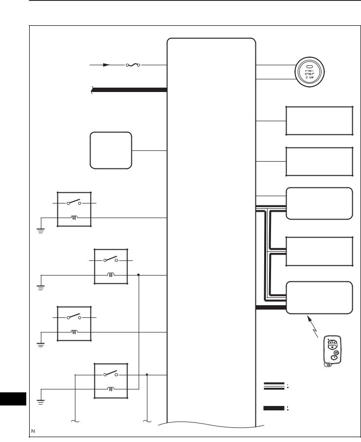
SYSTEM DIAGRAM
|
MAIN BODY ECU |
Engine Switch |
|
|
AM2 |
|
|
From Battery |
AM1 |
SSW1 |
|
AM2 |
|
||
|
|
|
|
|
|
SSW2 |
|
CAN Line |
CAN |
|
|
|
|
STP |
Stop Light Switch |
|
|
|
|
Shift Lock |
P |
|
|
Control ECU |
|
Combination Meter |
|
|
SPD |
||
|
|
|
|
IG1 |
|
|
|
|
|
SLP |
Steering Lock ECU |
|
|
|
|
|
|
LIN1 |
|
|
IG1D |
|
|
|
IG2 |
|
ID Code Box |
|
|
|
|
|
IG2D |
|
|
ACC |
|
|
Certification ECU |
|
|
|
|
|
ACCD |
|
|
|
ST CUT |
|
Key |
|
|
|
|
|
STR2 |
|
|
ST |
|
|
LIN |
|
|
CAN |
|
|
|
|
|
A |
B |
|
B137946E01 |
|
|
|
|
2GR-FE STARTING – SMART KEY SYSTEM |
ST–9 |
|
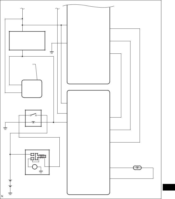
A |
B |
|
|
STR |
STSW |
|
|
|
Park / Neutral |
|
|
Position Switch |
|
TACH |
|
GND1 |
|
|
GND2 |
|
|
|
ACCR |
Transmission |
|
|
Control ECU |
|
|
|
MAIN BODY ECU |
|
STA |
|
|
NSW |
|
ECM |
|
|
|
ST |
NSW |
|
|
|
|
|
STAR |
ACCR |
|
|
|
|
STA |
|
|
|
TACH |
Starter |
|
STSW |
|
|
|
|
|
Crankshaft Position Sensor |
|
|
NE+ |
Battery |
|
NE- |
|
ST |
|
|
|
|
|
|
B137970E01 |
Communication table:
Transmitting ECU |
Receiving ECU |
Signal |
Communication method |
|
(Transmitter) |
(Receiver) |
|||
|
|
|||
|
|
|
|
|
Combination meter |
Main body ECU |
Vehicle speed signal |
CAN/Local communication |
|
|
|
|
|
|
Steering lock ECU |
Main body ECU |
Steering lock/unlock signal |
LIN/Local communication |
|
|
|
|
|

ST–10 |
2GR-FE STARTING – SMART KEY SYSTEM |
|
Transmitting ECU |
Receiving ECU |
Signal |
Communication method |
|
(Transmitter) |
(Receiver) |
|||
|
|
|||
|
|
|
|
|
|
|
Starter signal |
|
|
|
|
|
|
|
ECM |
Main body ECU |
Shift position signal |
CAN |
|
|
|
|
|
|
|
|
Engine revolution speed signal |
|
|
|
|
|
|
|
|
|
Engine switch position signal |
|
|
|
|
|
|
|
Main body ECU |
Certification ECU |
Courtesy light switch signal |
CAN |
|
|
||||
Wireless door lock buzzer |
||||
|
|
|
||
|
|
request signal |
|
|
|
|
|
|
|
Main body ECU |
Combination meter |
Entry start key signal |
CAN |
|
|
|
|
|
|
Main body ECU |
Combination meter |
Wireless door lock buzzer |
CAN |
|
request signal |
||||
|
|
|
||
|
|
|
|
|
Certification ECU |
Main body ECU |
Illumination light request signal |
CAN |
|
|
|
|
|
|
Certification ECU |
Driver seat ECU |
Memory call replay request signal |
CAN |
|
|
|
|
|
|
Certification ECU |
Main body ECU |
Light answer back signal |
CAN |
|
|
|
|
|
|
|
|
Meter buzzer single-shot request |
|
|
|
|
signal |
|
|
|
|
|
|
|
|
|
Meter buzzer intermittence |
|
|
|
|
request signal |
|
|
|
|
|
|
|
|
|
Meter buzzer continuation |
|
|
|
|
request signal |
|
|
Certification ECU |
Combination meter |
|
CAN |
|
Door open display signal |
||||
|
|
|
|
|
|
|
Key loss warning signal |
|
|
|
|
|
|
|
|
|
Low key battery warning signal |
|
|
|
|
|
|
|
|
|
Shift position warning signal |
|
|
|
|
|
|
|
|
|
Steering lock abnormal warning |
|
|
|
|
|
|
|
|
|
Steering lock unlock warning |
|
|
|
|
|
|
|
Combination meter |
Certification ECU/Main body ECU |
Vehicle speed signal |
CAN |
|
|
|
|
|
|
Shift lock control ECU |
Main body ECU |
Shift position signal |
CAN/Local communication |
|
|
|
|
|
|
Certification ECU |
Main body ECU |
Key ID matching request signal |
LIN |
|
|
|
|
|
|
Main body ECU |
Certification ECU |
ID required signal |
LIN |
|
|
|
|
|
ST
2GR-FE STARTING – SMART KEY SYSTEM |
ST–11 |
|
SYSTEM DESCRIPTION
1. PUSH-BUTTON START FUNCTION DESCRIPTION
(a) The push-button start function uses a push-type
|
|
engine switch, which the driver can operate by |
|
|
|
|
merely carrying the electrical key. This system |
|
|
|
|
consists primarily of the main body ECU, engine |
|
|
|
|
switch, ID code box, steering lock ECU, electrical |
|
|
|
|
key, ACC relay, IG1 relay, IG2 relay and certification |
|
|
|
|
ECU. The main body ECU controls the function. |
|
|
|
|
This function operates in cooperation with the smart |
|
|
|
|
key system. |
|
|
2. |
FUNCTION OF COMPONENT |
|
||
|
|
|
|
|
Component |
|
Function |
|
|
|
|
|
|
|
|
|
• Transmits engine switch signal to main body ECU. |
|
|
Engine Switch |
|
• Informs driver of power source mode or system abnormality with |
|
|
|
illumination of indicator light. |
|
|
|
• Transponder Key Amplifier |
|
|
|
|
|
• Receives ID code and transmits it to certification ECU when key |
|
|
|
|
|
|
|
|
|
|
battery is low. |
|
|
|
|
|
|
|
Electrical Key |
|
Receives signals from oscillators and returns ID code to entry door |
|
|
|
control receiver. |
|
|
|
|
|
|
|
|
|
|
|
|
|
Electrical Key Oscillator |
|
Receives request signals from certification ECU and forms detection |
|
|
• Console and Rear Seat |
|
area in vehicle interior. |
|
|
|
|
|
|
|
Steering Lock ECU |
|
Receives lock/unlock request signals from certification ECU and main |
|
|
|
body ECU. |
|
|
|
|
|
|
|
|
|
|
|
|
|
Entry Door Control Receiver |
|
Receives ID code from electrical key and transmits it to certification |
|
|
|
ECU. |
|
|
|
|
|
|
|
|
|
|
|
|
|
|
|
• Changes power source mode in 4 stages (off, on (ACC), on (IG), |
|
|
|
|
start) in accordance with shift position and state of stop light |
|
|
Main body ECU |
|
switch. |
|
|
|
|
• Controls push-button start function in accordance with signals |
|
|
|
|
received from switches and each ECU. |
|
|
|
|
|
|
|
Certification ECU |
|
Certifies ID code received from entry door control receiver and |
|
|
|
transmits certification results to ID code ECU and steering lock ECU. |
|
|
|
|
|
|
|
|
|
|
|
|
|
Stop Light Switch |
|
Outputs state of brake pedal to main body ECU. |
|
|
|
|
|
|
|
|
|
Receives steering unlock or engine immobiliser unset signals from |
|
|
ID Code Box |
|
certification ECU, certifies them, and transmits each unset signal to |
|
|
|
|
steering lock ECU or ECM. |
|
|
|
|
|
|
|
|
|
• Receives engine start request signal from main body ECU, turns |
|
|
ECM |
|
ON ST relay, and starts engine. |
|
|
|
• Receives signal from ID code ECU and performs engine ignition |
|
|
|
|
|
|
|
|
|
|
and injection. |
|
|
|
|
|
|
|
3. |
SYSTEM FUNCTION |
|
||
|
The electric controls of the push-button start function are |
|
||
|
described below: |
|
||
|
|
|
|
|
Control |
|
Outline |
|
|
|
|
|
|
|
|
|
• When driver operates engine switch with electrical key in driver's |
|
|
|
|
possession, certification ECU starts indoor electrical key oscillator, |
|
|
|
|
which transmits request signal to electrical key. Upon receiving |
|
|
|
ST |
|||
Engine switch control |
|
this signal, the electrical key transmits ID code signal to main body |
|
|
|
|
ECU. |
|
|
|
|
• ID code box verifies check results received from certification ECU |
|
|
|
|
via LIN and sends them to main body ECU. Based on these |
|
|
|
|
results, main body ECU authorizes operation of engine switch. |
|
|
|
|
|
|
|
Diagnosis |
|
When main body ECU detects malfunction, main body ECU |
|
|
|
diagnoses and memorizes failed section. |
|
|
|
|
|
|
|
|
|
|
|
|
|
ST–12 |
2GR-FE STARTING – SMART KEY SYSTEM |
|
4.CONSTRUCTION AND OPERATION
|
|
Indicator Light |
|
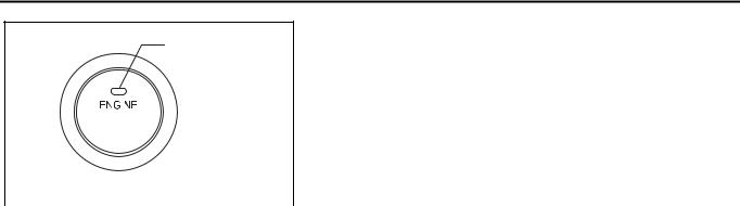
(a) |
Engine Switch |
|
||
|
|
|
|
|
|
The engine switch consists of a momentary type |
||
|
|
|
|
|
|
switch, 3 color (amber, green, greenish white) |
||
|
|
|
|
|
|
LEDs, and a transponder key amplifier. |
||
|
|
|
|
|
|
|||
|
START |
|
|
• The greenish white LED is for illumination. |
||||
|
STOP |
|
|
• The amber and green LEDs are for the indicator |
||||
|
|
|
|
|
|
lights. The driver can check the present power |
||
|
|
|
|
|
|
source mode and whether the engine can start in |
||
|
|
|
A109251E01 |
accordance with the illumination state of the |
||||
|
|
|
|
|
|
indicator light. |
||
|
|
|
|
|
|
|||
|
|
|
|
|
|
• When the main body ECU detects an |
||
|
|
|
|
|
|
abnormality in the push-button start function, it |
||
|
|
|
|
|
|
makes the amber indicator light flash. If the |
||
|
|
|
|
|
|
engine stopped in this state, it may not be |
||
|
|
|
|
|
|
possible to restart it. |
||
|
|
|
|
|
(b) |
Indicator Light Condition |
||
Engine switch indicator light condition: |
|
|
|
|||||
|
Power Source Mode/Condition |
|
|
|
Indicator Light Condition |
|||
|
|
|
|
|
|
|
||
|
Brake pedal released |
|
|
Brake pedal depressed, shift lever in P or N |
||||
|
|
|
|
|
||||
|
|
|
|
|
|
|
|
|
|
off |
|
|
OFF |
|
|
ON (Green) (When key and vehicle IDs match) |
|
|
|
|
|
|
|
|
||
|
on (ACC, IG) |
|
|
ON (Amber) |
|
ON (Green) |
||
|
|
|
|
|
|
|
|
|
|
Engine running |
|
|
OFF |
|
|
OFF |
|
|
|
|
|
|
|
|||
|
Steering lock not unlocked |
|
Flashes (Green) for 15 sec. |
|
Flashes (Green) for 15 sec. |
|||
|
|
|
|
|
|
|||
|
System malfunction |
|
Flashes (Amber) for 15 sec. |
|
Flashes (Amber) for 15 sec. |
|||
|
|
|
|
|
|
|
|
|
|
|
|
|
|
(c) |
Main body ECU |
|
|
|
|
|
|
|
|
The main body ECU consists of the IG1 and IG2 |
||
|
|
|
|
|
|
relay actuation circuits and CPU. |
||
|
|
|
|
|
|
HINT: |
|
|
Before removing the battery, make sure to turn the engine switch off. The main body ECU constantly stores the present power source mode in its memory. Therefore, if the main body ECU is interrupted by disconnecting the battery, the main body ECU restores the power source mode after the battery is reconnected. For this reason, if the battery is disconnected when the engine switch is not off, the power will be restored to the vehicle at the same time the power is restored to the main body ECU (by reconnecting the battery).
5.PUSH-BUTTON START FUNCTION OPERATION
(a)This system has different power source mode patterns depending on the brake pedal condition and shift lever position.
|
|
Brake Pedal |
Shift Lever |
Power Source Mode Pattern |
|
ST |
|||||
|
|
|
|
||
|
|
|
When the engine switch is pushed once. |
||
|
|
|
|
||
|
|
Depressed |
P or N position |
• off → engine start |
|
|
|
• on (ACC) → engine start |
|||
|
|
|
|
||
|
|
|
|
• on (IG) → engine start |
|
|
|
|
|
|
|
|
|
|
P position |
Each time the engine switch is pushed. |
|
|
|
|
• off → on (ACC) → on (IG) → off |
||
|
|
Not depressed |
|
||
|
|
|
|
||
|
|
Except P position |
Each time the engine switch is pushed. |
||
|
|
|
|||
|
|
|
• off → on (ACC) → on (IG) → on (ACC) |
||
|
|
|
|
||
|
|
|
|
|

|
2GR-FE STARTING – SMART KEY SYSTEM |
ST–13 |
||
|
|
|||
|
|
|
|
|
Brake Pedal |
|
Shift Lever |
Power Source Mode Pattern |
|
|
|
|
|
|
|
|
|
When the engine switch is pushed with power |
|
- |
|
P position |
source mode on (IG) (engine running). |
|
|
|
|
• on (IG) → off |
|
|
|
|
|
|
|
|
|
When the engine switch is pushed with power |
|
- |
|
Except P position |
source mode on (IG) (engine running). |
|
|
|
|
• on (IG) → on (ACC) |
|
|
|
|
|
|
When the battery of the key is low, the push-button start function can be operated by holding the key against the engine switch.
• After approximately 1 hour has passed with the engine switch on (ACC) and the shift position in P, the main body ECU will automatically cut the power supply (the power source mode changes to off).
ST

ST–14 |
2GR-FE STARTING – SMART KEY SYSTEM |
|
• The illustration below shows the transition of power source modes.
Transition of power source mode:
Shift Position
|
|
P |
|
|
N |
Except P and N |
|
Engine Switch |
|
|
|
|
|
|
|
Position |
Engine |
Engine |
Not |
Engine |
Engine |
Engine |
Engine |
|
switch |
switch |
operated |
switch |
switch |
switch |
switch |
|
pushed |
pushed |
for 1 |
pushed |
pushed |
pushed |
pushed |
|
|
|
hour |
|
|
|
|
|
|
Brake |
|
|
Brake pedal |
|
Brake pedal |
|
|
pedal |
|
|
depressed |
|
depressed |
|
|
depressed |
|
|
|
|
|
off |
|
|
|
|
|
|
|
on (ACC) |
|
|
|
|
|
|
|
on (IG) |
|
|
|
|
|
|
|
Engine |
|
|
|
|
|
|
|
start |
|
|
|
|
|
|
|
Transition of power source |
Transition of power source |
Transition of power source mode |
mode (Always) |
mode (only when key |
(only with vehicle stopped) |
|
code is certified) |
|
ST |
B138065E01 |
|

2GR-FE STARTING – SMART KEY SYSTEM |
ST–15 |
|
|
|
HINT: |
|
|
While the vehicle is being driven normally, |
|
|
operation of the engine switch is disabled. |
|
|
However, if the engine must be stopped in an |
|
|
emergency while the vehicle is being driven, |
|
|
pressing the engine switch for 3 seconds or more |
|
|
stops the engine. Power source mode changes |
|
|
from start to on (ACC). |
|
6. WHEN KEY BATTERY IS LOW |
|
Required Distance: |
(a) |
To operate the push-button start function when the |
10 mm (0.39 in.) |
|
key battery is low, hold the key close to the engine |
|
|
switch with the brake pedal depressed. |
|
(b) |
The main body ECU transmits a key verification |
|
|
request signal from the stop light switch to the |
|
|
certification ECU. |
Engine Switch |
(c) |
The certification ECU does not receive an ID code |
|
response from the entry door control receiver, so it |
|
|
|
actuates the transponder key amplifier built into the |
|
|
engine switch. |
|
(d) |
The transponder key amplifier outputs an engine |
|
|
immobiliser radio wave to the key. |
|
(e) |
The key receives the radio wave, and returns a |
|
|
radio wave response to the transponder key |
|
|
amplifier. |
Key |
(f) |
The transponder key amplifier combines the key ID |
|
|
codes with the radio wave response, and transmits |
|
|
it to the certification ECU. |
|
(g) |
The certification ECU judges and verifies the ID |
|
B137947E01 |
code, and transmits a key verification OK signal to |
|
|
the main body ECU. The buzzer in the combination |
|
|
meter sounds at the same time. |
(h)After the buzzer sounds, if the engine switch is pressed within 5 seconds with the brake pedal not depressed, the power source mode changes to on (ACC) or on (IG), the same as in the normal condition.
7.DIAGNOSIS
The main body ECU can detect malfunctions in the pushbutton start function when the power source mode is on (IG). When the ECU detects a malfunction, the amber indicator light of the engine switch flashes to warn the driver. At the same time, the ECU stores a 5-digit DTC (Diagnostic Trouble Code) in the memory.
•The indicator light warning continues for 15 seconds even after the power source mode is changed to off.
• The DTC can be read by connecting the intelligent tester |
ST |
to the DLC3. |
•The push-button start function cannot be operated if a malfunction occurs.

ST–16 |
2GR-FE STARTING – SMART KEY SYSTEM |
|
HOW TO PROCEED WITH TROUBLESHOOTING
HINT:
• Use the following procedures to troubleshoot the pushbutton start function.
• The intelligent tester should be used in steps 4, 5 and 8.
1 VEHICLE BROUGHT TO WORKSHOP
NEXT
2 CUSTOMER PROBLEM ANALYSIS CHECK
HINT:
• In troubleshooting, confirm that the problem symptoms have been accurately identified. Preconceptions should be discarded in order to make an accurate judgment. To clearly understand what the problem symptoms are, it is extremely important to ask the customer about the problem and the conditions at the time the malfunction occurred.
|
• Gather as much information as possible for reference. |
|
|
Past problems that seem unrelated may also help in some |
|
|
cases. |
|
|
• The following 5 items are important points in the problem |
|
|
analysis: |
|
|
|
|
What |
|
Vehicle model, system name |
|
|
|
When |
|
Date, time, occurrence frequency |
|
|
|
Where |
|
Road conditions |
|
|
|
Under what conditions? |
|
Running conditions, driving conditions, weather conditions |
|
|
|
How did it happen? |
|
Problem symptoms |
|
|
|
NEXT
3 INSPECT BATTERY VOLTAGE
Standard voltage: 11 to 14 V
If the voltage is below 11 V, recharge or replace the battery before proceeding.
ST NEXT
4INSPECT COMMUNICATION FUNCTION OF CAN COMMUNICATION SYSTEM
(a)Use the intelligent tester to check if the CAN Communication System is functioning normally (See page CA-8).
2GR-FE STARTING – SMART KEY SYSTEM |
ST–17 |
|
|
||
|
Result |
|
|
|
|
|
Result |
Proceed to |
|
|
|
|
CAN DTC is not output |
A |
|
|
|
|
CAN DTC is output |
B |
|
|
|
B GO TO CAN COMMUNICATION SYSTEM
A
5 CHECK FOR DTC
(a)Check for DTCs and note any codes that are output (See page ST-26).
(b)Delete DTCs.
(c)Recheck for DTCs.
Result
Result |
Proceed to |
|
|
DTC does not reoccur |
A |
|
|
DTC reoccurs |
B |
|
|
BGO TO DIAGNOSTIC TROUBLE CODE CHART
A
6 INSPECT BASIC OPERATION
(a)Turn the engine switch on (START) and check that the engine starts normally. Make sure the brake pedal is depressed and the shift position is P at this time.
(b)Check that the engine switch mode can be changed by pushing the engine switch.
HINT:
Without depressing the brake pedal, push the engine switch repeatedly. Engine switch mode should turn from off to on (ACC) to on (IG) and back to off.
With the brake pedal depressed, push the engine switch repeatedly. Engine switch mode should turn to ENGINE START from any status.
OK:
Engine can start normally.
NEXT
7 PROBLEM SYMPTOMS TABLE
Result
ST
Result |
Proceed to |
|
|
Fault is not listed in the problem symptoms table |
A |
|
|
Fault is listed in the problem symptoms table |
B |
|
|
ST–18 |
2GR-FE STARTING – SMART KEY SYSTEM |
|||
|
||||
|
|
B |
|
|
|
|
|
Go to step 9 |
|
|
|
|
|
|
|
|
|
|
|
A |
|
|
|
|
8OVERALL ANALYSIS AND TROUBLESHOOTING
(a)Terminals of ECU (See page ST-19)
(b)DATA LIST/ACTIVE TEST (See page ST-26)
NEXT
9 REPAIR OR REPLACE
NEXT
10 CONFIRMATION TEST
NEXT
END
ST

2GR-FE STARTING – SMART KEY SYSTEM |
ST–19 |
|
PROBLEM SYMPTOMS TABLE
HINT:
•Use the table below to help determine the cause of the problem symptom. The potential causes of the symptoms are listed in order of probability in the "Suspected area" column of the table. Check each symptom by checking the suspected areas in the order they are listed. Replace parts as necessary.
•Inspect the fuses and relays related to the system before inspecting the suspected areas below.
PUSH-BUTTON START FUNCTION:
Symptom |
|
Suspected area |
See page |
|
|
|
|
|
|
|
1. |
AM2 Fuse |
ST-114 |
|
|
|
|
|
|
|
2. |
Engine Switch |
- |
|
|
|
|
|
|
|
3. |
Wire Harness or Connector |
- |
|
|
|
|
||
Power does not turn on (neither ACC nor IG is |
4. Main Body ECU (Instrument Panel J/B) |
- |
||
possible). |
5. Certification ECU |
- |
||
|
|
|
|
|
|
6. |
ID Code Box |
- |
|
|
|
|
|
|
|
7. |
Steering Lock ECU |
- |
|
|
|
|
|
|
|
8. |
Smart Key System (Entry Function) |
- |
|
|
|
|
||
|
1. AM2 Fuse |
ST-131 |
||
|
|
|
||
Power is not turned on (only ACC is not turned on). |
2. Wire Harness or Connector |
- |
||
|
|
|
|
|
|
3. |
Main Body ECU (Instrument Panel J/B) |
- |
|
|
|
|
||
|
1. AM2 Fuse |
ST-122 |
||
|
|
|
|
|
|
2. |
IG1 Relay |
- |
|
|
|
|
||
Power is not turned on (only IG is not turned on). |
3. IG2 Relay |
- |
||
|
|
|
|
|
|
4. |
Wire Harness or Connector |
- |
|
|
|
|
|
|
|
5. |
Main Body ECU (Instrument Panel J/B) |
- |
|
|
|
|
|
|
|
1. |
Main Body ECU (Instrument Panel J/B) |
ST-95 |
|
|
|
|
|
|
|
2. |
Certification ECU |
- |
|
|
|
|
|
|
|
3. |
Shift Lock Control ECU |
- |
|
|
|
|
|
|
|
4. |
ID Code Box |
- |
|
|
|
|
|
|
Engine does not start. |
5. |
Stop SW Fuse |
- |
|
|
|
|
||
6. |
Stop Light Switch |
- |
||
|
||||
|
|
|
|
|
|
7. |
Electrical Steering Lock Function |
- |
|
|
|
|
|
|
|
8. |
Engine Control System |
- |
|
|
|
|
|
|
|
9. |
Engine Immobiliser System |
- |
|
|
|
|
||
|
10. Wire Harness or Connector |
- |
||
|
|
|
||
Engine switch indicator light does not come on. |
Engine Switch Indicator Light Circuit |
ST-110 |
||
|
|
|
|
|
ST

ST–20 |
2GR-FE STARTING – SMART KEY SYSTEM |
|
TERMINALS OF ECU
1.CHECK MAIN BODY ECU (INSTRUMENT PANEL J/B)
Front Side: |
|
|
|
|
|
IK |
IM |
|
|
IJ |
|
IL |
IF |
|
|
IE |
|
|
|
|
|
||
IC |
ID |
|
|
|
|
|
|
|
IR |
|
IN |
|
IB |
IA |
IP |
IO |
|
Back Side: |
|
|
|
|
|
|
|
E7 |
E6 |
E8 |
E9 |
|
|
IG |
II |
IH |
|
ST |
|
|
|
|
|
|
|
|
|
|
B112605E03 |
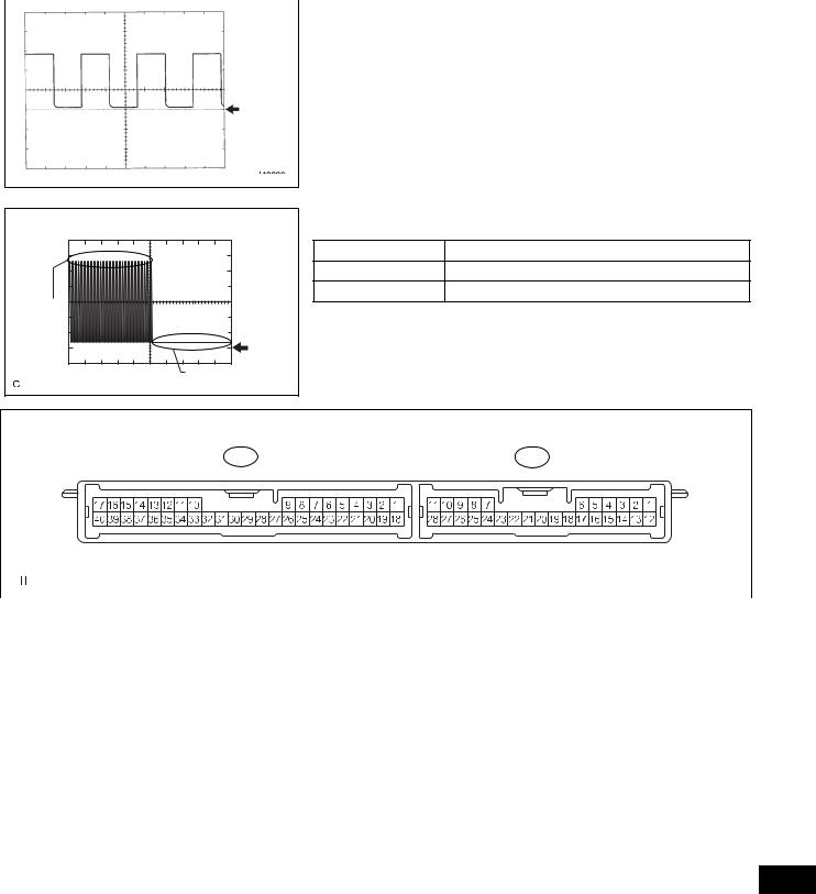
(a)Disconnect the IR, IA, IK, ID, IF, IM E6, E7 and E8 ECU connectors.
2GR-FE STARTING – SMART KEY SYSTEM |
ST–21 |
|
(b)Measure the voltage and resistance of the wire harness side connector.
Symbols (Terminal No.) |
Wiring Color |
Terminal Description |
Condition |
Specified Condition |
|
|
|
|
|
AM1 (E7-6) - Body ground |
L - Body ground |
+B power supply |
Always |
10 to 14 V |
|
|
|
|
|
AM2 (E6-1) - Body ground |
L - Body ground |
+B power supply |
Always |
10 to 14 V |
|
|
|
|
|
SSW1 (E7-17) - Body ground |
L - Body ground |
Engine switch signal |
Engine switch pushed |
Below 1 Ω |
|
|
|
|
|
SSW1 (E7-17) - Body ground |
L - Body ground |
Engine switch signal |
Engine switch not pushed |
10 kΩ or higher |
|
|
|
|
|
SSW2 (E7-16) - Body ground |
V - Body ground |
Engine switch signal |
Engine switch pushed |
Below 1 Ω |
|
|
|
|
|
SSW2 (E7-16) - Body ground |
V - Body ground |
Engine switch signal |
Engine switch not pushed |
10 kΩ or higher |
|
|
|
|
|
GND3 (E8-1) - Body ground |
W-B - Body ground |
Ground |
Always |
Below 1 Ω |
|
|
|
|
|
LIN1 (IR-9) - Body ground |
O - Body ground |
LIN line |
Always |
10 kΩ or higher |
|
|
|
|
|
BATB (IA-1) - Body ground |
B - Body ground |
+B Power supply |
Always |
10 to 14 V |
|
|
|
|
|
GND1 (IF-10) - Body ground |
W-B - Body ground |
Ground |
Always |
Below 1 Ω |
|
|
|
|
|
GND2 (IM-9) - Body ground |
W-B - Body ground |
Ground |
Always |
Below 1 Ω |
|
|
|
|
|
CANN (E8-15) - Body ground |
W - Body ground |
CAN Line |
Always |
10 kΩ or higher |
|
|
|
|
|
CANP (E8-16) - Body ground |
L - Body ground |
CAN Line |
Always |
10 kΩ or higher |
|
|
|
|
|
CANH (E8-5) - Body ground |
R - Body ground |
CAN Line |
Always |
10 kΩ or higher |
|
|
|
|
|
CANL (E8-6) - Body ground |
W - Body ground |
CAN Line |
Always |
10 kΩ or higher |
|
|
|
|
|
ACC (IA-1) - Body ground |
B - Body ground |
ACC power supply |
Always |
10 to 14 V |
|
|
|
|
|
IG (IA-1) - Body ground |
B - Body ground |
IG power supply |
Always |
10 to 14 V |
|
|
|
|
|
If the result is not as specified, there may be a malfunction on the wire harness side.
(c)Reconnect the ECU connectors.
(d)Measure the voltage of the connector.
Symbols (Terminal No.) |
Wiring Color |
Terminal Description |
Condition |
Specified Condition |
|
|
|
|
|
|
|
|
|
|
|
|
|
|
|
Output voltage at terminal |
|
|
|
ACCD (E7-22) - GND3 (E8-1) |
W - W-B |
ACC signal |
Engine switch on (ACC) |
AM1 or AM2 is -2 V or |
|
|
|
|
|
|
|
more. |
|
|
|
|
|
|
|
|
|
|
|
ACCD (E7-22) - GND3 (E8-1) |
W - W-B |
ACC signal |
Engine switch off |
Below 1 V |
|
|
|
|
|
|
|
|
|
|
|
|
|
|
|
Output voltage at terminal |
|
|
|
IG1D (E7-3) - GND3 (E8-1) |
P - W-B |
IG1 signal |
Engine switch on (IG) |
AM1 or AM2 is -2 V or |
|
|
|
|
|
|
|
more. |
|
|
|
|
|
|
|
|
|
|
|
IG1D (E7-3) - GND3 (E8-1) |
P - W-B |
IG1 signal |
Engine switch on (ACC) |
Below 1 V |
|
|
|
|
|
|
|
|
|
|
|
|
|
|
|
Output voltage at terminal |
|
|
|
IG2D (E6-11) - GND3 (E8-1) |
LG - W-B |
IG2 signal |
Engine switch on (IG) |
AM1 or AM2 is -2 V or |
|
|
|
|
|
|
|
more. |
|
|
|
|
|
|
|
|
|
|
|
IG2D (E6-11) - GND3 (E8-1) |
LG - W-B |
IG2 signal |
Engine switch on (ACC) |
Below 1 V |
|
|
|
|
|
|
|
|
|
|
|
|
|
|
|
Output voltage at terminal |
|
|
|
STP (IL-7) - GND3 (E8-1) |
L - W-B |
Stop light signal |
Brake pedal depressed |
AM1 or AM2 is -2 V or |
|
|
|
|
|
|
|
more. |
|
|
|
|
|
|
|
|
|
|
|
STP (IL-7) - GND3 (E8-1) |
L - W-B |
Stop light signal |
Brake pedal released |
Below 1 V |
|
|
|
|
|
|
|
|
|
|
|
SLR+ (E7-19) - GND3 (E8-1) |
BR - W-B |
Steering lock motor signal |
Steering lock motor |
Below 1 V |
|
|
|
operating |
|
|
|||||
|
|
|
|
|
|
||
|
|
|
|
|
|
|
|
|
|
|
Steering lock motor does |
Output voltage at terminal |
|
|
|
SLR+ (E7-19) - GND3 (E8-1) |
BR - W-B |
Steering lock motor signal |
AM1 or AM2 is -2 V or |
|
|
||
not operate |
|
|
|||||
|
|
|
more. |
|
ST |
||
|
|
|
|
|
|||
|
|
|
|
|
|
||
SLP (E7-18) - GND3 (E8-1) |
P - W-B |
Steering lock actuator |
Steering lock is locked |
Pulse generation |
|
||
|
|||||||
position signal |
(See waveform 3) |
|
|
||||
|
|
|
|
|
|||
|
|
|
|
|
|
|
|
SLP (E7-18) - GND3 (E8-1) |
P - W-B |
Steering lock actuator |
Steering lock is released |
Pulse generation |
|
|
|
position signal |
(See waveform 3) |
|
|
||||
|
|
|
|
|
|||
|
|
|
|
|
|
|
|
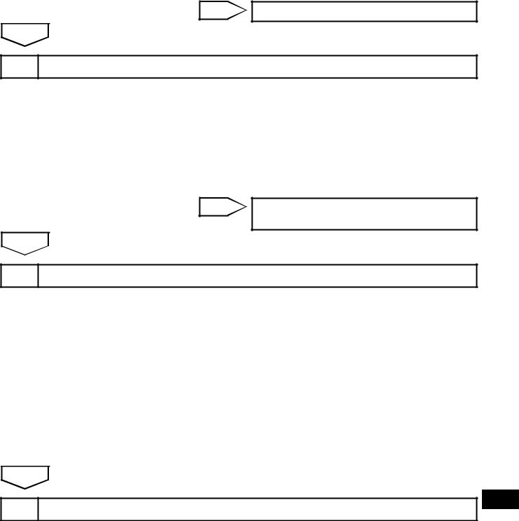
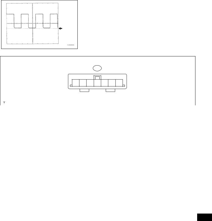
SPD (E8-9) - GND3 (E8-1) |
V - W-B |
Vehicle speed signal |
Engine switch on (IG), |
Pulse generation |
|
|
|
rotate rear wheel slowly |
(See waveform 1) |
|
|
||||
|
|
|
|
|
|||
|
|
|
|
|
|
|
|
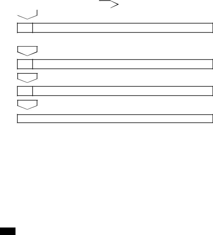
TACH (E8-8) - GND3 (E8-1) |
B - W-B |
Tachometer signal |
Engine running |
Pulse generation |
|
|
|
(See waveform 2) |
|
|
|||||
|
|
|
|
|
|
||
|
|
|
|
|
|
|

ST–22 |
2GR-FE STARTING – SMART KEY SYSTEM |
|
Symbols (Terminal No.) |
Wiring Color |
Terminal Description |
Condition |
Specified Condition |
|
|
|
|
|
|
|
|
|
|
|
Output voltage at terminal |
|
P (E9-2) - GND3 (E8-1) |
G - W-B |
Shift lock signal |
Shift lever P position |
AM1 or AM2 is -2 V or |
|
|
|
|
|
more. |
|
|
|
|
|
|
|
P (E9-2) - GND3 (E8-1) |
G - W-B |
Shift lock signal |
Shift lever not P position |
Below 1 V |
|
|
|
|
|
|
|
|
|
|
Brake pedal depressed, |
0.1 to 0.8 V *1 |
|
ACCR (E6-3) - GND3 (E8-1) |
P - W-B |
Starter assist signal |
shift lever P position, |
→ Output voltage at |
|
engine switch is pushed |
terminal AM1 or AM2 is -2 |
||||
|
|
|
|||
|
|
|
once → on (IG) |
V or more. |
|
|
|
|
|
|
|
|
|
Starter activation request |
Brake pedal depressed, |
Output voltage at terminal |
|
STSW (E9-4) - GND3 (E8-1) |
GR - W-B |
AM1 or AM2 is -2 V or |
|||
signal |
engine switch held on (ST) |
||||
|
|
more. |
|||
|
|
|
|
||
|
|
|
|
|
|
STR (E7-8) - GND3 (E8-1) |
G - W-B |
Park/neutral position |
Shift lever P or N position |
Below 1 V |
|
switch |
|||||
|
|
|
|
||
|
|
|
|
|
|
|
|
|
Brake pedal depressed, |
Output voltage at terminal |
|
STR2 (E9-6) - GND3 (E8-1) |
V - W-B |
Starter signal |
shift lever P or N position, |
AM1 or AM2 is -3.5 V or |
|
|
|
|
engine switch on (ST) |
more. *2 |
|
|
|
|
Brake pedal depressed, |
Output voltage at terminal |
|
INDS (E7-15) - GND3 (E8-1) |
LG - W-B |
Vehicle condition signal |
AM1 or AM2 is -3 V or |
||
shift lever P position. |
|||||
|
|
|
more. |
||
|
|
|
|
||
|
|
|
|
|
|
|
|
|
Brake pedal depressed, |
Output voltage at terminal |
|
|
|
|
shift lever P position, |
||
INDW (E7-14) - GND3 (E8-1) |
P - W-B |
Warning signal |
AM1 or AM2 is -3 V or |
||
engine switch on (ACC, |
|||||
|
|
|
more. |
||
|
|
|
IG) |
||
|
|
|
|
||
|
|
|
|
|
|
|
|
|
Light control switch TAIL |
Output voltage at terminal |
|
SWIL (E7-25) - GND3 (E8-1) |
O - W-B |
Illumination signal |
AM1 or AM2 is -2 V or |
||
or HEAD |
|||||
|
|
|
more. |
||
|
|
|
|
||
|
|
|
|
|
GND
I042329E01
HINT:
*1: Voltage is output only when the engine is cranking.
*2: Voltage is output for 0.3 seconds when the engine is cranking to start. Disconnect the C55 connector from the ECM before measuring the voltage.
If the result is not as specified, the ECU may have a malfunction.
(e) Using an oscilloscope, check the signal waveform of the ECU.
(1) Waveform 1
Waveform 1 (Reference):
Terminal No. |
E8-9 (SPD) - Body ground |
|
|
Tool Setting |
5 V/DIV., 10 ms./DIV. |
|
|
Vehicle Condition |
Driving at approx. 20 km/h (12 mph) |
|
|
HINT:
As the vehicle speed increases, the wavelength shortens.
ST
|
2GR-FE STARTING – SMART KEY SYSTEM |
ST–23 |
|||
|
|
||||
|
|
|
(2) Waveform 2 |
|
|
|
|
|
|||
|
|
|
Waveform 2 (Reference): |
|
|
|
|
|
Terminal No. |
E8-8 (TACH) - Body ground |
|
|
|
|
|
|
|
|
|
|
Tool Setting |
5 V/DIV., 10 ms./DIV. |
|
|
|
|
|
|
|
|
|
|
Vehicle Condition |
Engine idling |
|
|
|
|
|
|
|
|
GND |
|
HINT: |
|
|
|
|
As the engine revolution speed increases, the |
|
|
|
|
wavelength shortens. |
|
|
I042330E01 |
|
|
|
|
|
(3) Waveform 3 |
||
|
|
|
Waveform 3 (Reference): |
|
|
Terminal No. |
|
E7-18 (SLP) - Body ground |
|
|
Tool Setting |
|
2 V/DIV., 100 ms./DIV. |
|
|
Vehicle Condition |
Steering lock/unlock |
||
Lock |
2. |
CHECK CERTIFICATION ECU |
||
|
||||
|
GND |
|
|
|
|
Unlock |
|
|
|
|
A130277E01 |
|
|
|
|
E58 |
|
|
E59 |
|
|
|
|
|
|
|
|
|
|
|
|
E125964E05 |
|
|
|
|
|
|
|
|
|
|
(a) Disconnect the E58 ECU connector. |
||||
|
|
(b) Measure the voltage and resistance of the wire |
||||
|
|
harness side connector. |
|
|
|
|
|
|
|
|
|
||
Symbols (Terminal No.) |
Wiring Color |
Terminal Description |
Condition |
Specified Condition |
||
|
|
|
|
|
||
+B (E58-1) - Body ground |
W - Body ground |
+B power supply |
Always |
10 to 14 V |
||
|
|
|
|
|
||
IG (E58-18) - Body ground |
LG - Body ground |
Ignition power supply |
Engine switch on (IG) |
10 to 14 V |
||
|
|
|
|
|
||
IG (E58-18) - Body ground |
LG - Body ground |
Ignition power supply |
Engine switch off |
Below 1 V |
||
|
|
|
|
|
||
LIN (E58-10) - Body ground |
O - Body ground |
LIN line |
Always |
10 kΩ or higher |
||
|
|
|
|
|
||
E (E58-17) - Body ground |
W-B - Body ground |
Ground |
Always |
Below 1 Ω |
||
|
|
|
|
|
|
|
If the result is not as specified, there may be a malfunction on the wire harness side.
ST

|
|
ST–24 |
|
|
|
|
|
|
|
|
2GR-FE STARTING – SMART KEY SYSTEM |
|
|
|
|
|
|
|
|
|
|
|||||||||||||||
|
|
|
|
|
|
|
|
|
|
|
|
|
|
|
|
|
|
|
|
|
||||||||||||||||
|
|
|
|
|
|
|
|
|
|
|
|
|
|
|
|
3. |
CHECK ECM |
|
|
|
|
|
|
|
|
|
|
|
|
|||||||
|
|
|
|
|
|
|
|
|
|
|
|
|
|
|
|
|
|
|
|
|
|
|
|
|
|
|
|
|
|
|
|
|
|
|||
|
|
|
|
|
|
|
|
|
|
|
C55 |
|
|
|
|
|
|
|
|
|
|
|
|
|
|
|
|
A55 |
|
|
|
|
||||
|
|
|
|
|
|
|
|
|
|
|
|
|
|
|
|
|
|
|
|
|
|
|
|
|
|
|
|
|
|
|
|
|
|
|
|
|
|
|
|
|
|
|
|
|
|
|
|
|
|
|
|
|
|
|
|
|
|
|
|
|
|
|
|
|
|
|
|
|
|
|
|
|
|
|
|
|
|
|
|
|
|
|
|
|
|
|
|
|
|
|
|
|
|
|
|
|
|
|
|
|
|
|
|
|
|
|
|
|
|
|
|
|
|
|
|
|
|
|
|
|
|
|
|
|
|
|
|
|
|
|
|
|
|
|
|
|
|
|
|
|
|
|
|
|
|
|
|
|
|
|
|
|
|
|
|
|
|
|
|
|
|
|
|
|
|
|
|
|
|
|
|
|
|
|
|
|
|
|
|
|||||
|
|
|
|
|
|
|
|
|
|
|
|
|
|
|
|
|
|
|
||||||||||||||||||
|
|
|
|
|
|
|
|
|
|
|
|
|
|
|
|
|
|
|
|
|
|
|
|
|
|
|
|
|
|
|
|
|
|
|
|
A107881E32 |
|
|
|
|
|
|
|
|
|
|
|
|
|
|
|
|
|
|
|
|
|
||||||||||||||||
|
|
|
|
|
|
|
|
|
|
|
|
|
|
|
|
|
|
(a) Disconnect the C55 and A55 ECM connectors. |
||||||||||||||||||
|
|
|
|
|
|
|
|
|
|
|
|
|
|
|
|
|
|
(b) Measure the voltage and resistance of the wire |
||||||||||||||||||
|
|
|
|
|
|
|
|
|
|
|
|
|
|
|
|
|
|
|
|
harness side connectors. |
|
|
|
|
|
|
|
|
||||||||
|
|
|
|
|
|
|
|
|
|
|
|
|
|
|
|
|||||||||||||||||||||
|
|
Symbols (Terminal No.) |
|
|
Wiring Color |
|
|
Terminal Description |
|
Condition |
|
|
|
|
Specified Condition |
|||||||||||||||||||||
|
|
|
|
|
|
|
|
|
|
|
|
|
|
|
|
|||||||||||||||||||||
|
|
+B (A55-2) - Body ground |
|
R - Body ground |
|
|
Power source of ECM |
|
Engine switch on (IG) |
|
|
|
|
|
10 to 14 V |
|||||||||||||||||||||
|
|
+B2 (A55-1) - Body ground |
|
R - Body ground |
|
|
Power source of ECM |
|
Engine switch on (IG) |
|
|
|
|
|
10 to 14 V |
|||||||||||||||||||||
|
|
IGSW (A55-28) - Body ground |
|
Y - Body ground |
|
|
Ignition switch signal |
|
Engine switch on (IG) |
|
|
|
|
|
10 to 14 V |
|||||||||||||||||||||
|
|
E01 (C55-22) - Body ground |
|
W-B - Body ground |
|
|
|
Ground |
|
|
|
Always |
|
|
|
|
|
|
|
Below 1 Ω |
||||||||||||||||
|
|
E02 (C55-21) - Body ground |
|
W-B - Body ground |
|
|
|
Ground |
|
|
|
Always |
|
|
|
|
|
|
|
Below 1 Ω |
||||||||||||||||
|
|
E03 (C55-104) - Body ground |
|
B - Body ground |
|
|
|
|
Ground |
|
|
|
Always |
|
|
|
|
|
|
|
Below 1 Ω |
|||||||||||||||
|
|
E04 (C55-23) - Body ground |
|
W - Body ground |
|
|
|
|
Ground |
|
|
|
Always |
|
|
|
|
|
|
|
Below 1 Ω |
|||||||||||||||
|
|
E05 (C55-46) - Body ground |
|
W - Body ground |
|
|
|
|
Ground |
|
|
|
Always |
|
|
|
|
|
|
|
Below 1 Ω |
|||||||||||||||
|
|
E1 (C55-81) - Body ground |
|
W-B - Body ground |
|
|
|
Ground |
|
|
|
Always |
|
|
|
|
|
|
|
Below 1 Ω |
||||||||||||||||
|
|
ME01 (C55-20) - Body ground |
|
B - Body ground |
|
|
|
|
Ground |
|
|
|
Always |
|
|
|
|
|
|
|
Below 1 Ω |
|||||||||||||||
|
|
|
|
|
|
|
|
|
|
|
|
|
|
|
|
|
|
|
|
If the result is not as specified, there may be a |
||||||||||||||||
|
|
|
|
|
|
|
|
|
|
|
|
|
|
|
|
|
|
|
|
malfunction on the wire harness side. |
|
|||||||||||||||
|
|
|
|
|
|
|
|
|
|
|
|
|
|
|
|
|
|
(c) Reconnect the ECM connectors. |
|
|
|
|||||||||||||||
|
|
|
|
|
|
|
|
|
|
|
|
|
|
|
|
|
|
(d) Measure the voltage of the connectors. |
|
|||||||||||||||||
|
|
|
|
|
|
|
|
|
|
|
|
|
|
|
|
|||||||||||||||||||||
|
|
Symbols (Terminal No.) |
|
|
Wiring Color |
|
|
Terminal Description |
|
Condition |
|
|
|
|
Specified Condition |
|||||||||||||||||||||
|
|
|
|
|
|
|
|
|
|
|
|
|
|
|
|
|
|
|
|
|
|
|
|
|
|
|
|
|
|
|
||||||
|
|
STA (A55-48) - E1 (C55-81) |
|
|
|
V - W-B |
|
|
|
Starter relay operation |
|
Cranking |
|
|
|
|
|
|
10 to 14 V |
|||||||||||||||||
|
|
|
|
|
|
|
|
|
|
signal |
|
|
|
|
|
|
|
|
|
|||||||||||||||||
|
|
|
|
|
|
|
|
|
|
|
|
|
|
|
|
|
|
|
|
|
|
|
|
|
|
|
|
|
|
|
|
|
|
|||
|
|
|
|
|
|
|
|
|
|
|
|
|
|
|
|
|
|
|
|
|
|
|
|
|
|
|
|
|
|
|
|
|||||
|
|
|
|
|
|
|
|
|
|
|
|
|
|
|
|
|
|
|
|
|
|
|
|
|
Brake pedal depressed, |
|
|
0.1 to 0.8 V *1 → Output |
||||||||
|
|
ACCR (A55-13) - E1 (C55-81) |
|
|
|
B - W-B |
|
|
|
ACC relay cut signal |
|
shift lever P position, |
|
|
|
|||||||||||||||||||||
|
|
|
|
|
|
|
|
|
|
|
|
voltage at terminal AM1 or |
||||||||||||||||||||||||
|
|
|
|
|
|
|
|
|
|
(output) |
|
|
|
engine switch is pushed |
|
|
||||||||||||||||||||
|
|
|
|
|
|
|
|
|
|
|
|
|
|
|
|
|
|
|
|
|
|
|
|
AM2 is -2 V or more. |
||||||||||||
|
|
|
|
|
|
|
|
|
|
|
|
|
|
|
|
|
|
|
|
|
|
|
|
|
once → on (IG) |
|
|
|
||||||||
|
|
|
|
|
|
|
|
|
|
|
|
|
|
|
|
|
|
|
|
|
|
|
|
|
|
|
|
|
|
|
|
|||||
|
|
TACH (A55-15) - E1 (C55-81) |
|
|
|
B - W-B |
|
|
Engine revolution signal |
|
Idling |
|
|
|
|
|
Pulse generation (see |
|||||||||||||||||||
|
|
|
|
|
|
|
|
|
|
(output) |
|
|
|
|
|
|
|
|
|
|
waveform 1) |
|||||||||||||||
|
|
|
|
|
|
|
|
|
|
|
|
|
|
|
|
|
|
|
|
|
|
|
|
|
|
|
|
|
|
|
||||||
|
|
|
|
|
|
|
|
|
|
|
|
|
|
|
|
|
|
|
|
|
|
|
|
|
|
|
|
|
|
|
||||||
|
|
|
|
|
|
|
|
|
|
|
|
|
|
|
|
|
Stop light switch signal |
|
|
|
|
|
|
|
|
|
|
|
|
|
||||||
ST |
|
STP (A55-36) - E1 (C55-81) |
|
|
|
W - W-B |
|
|
|
|
Brake pedal depressed |
|
|
|
|
7.5 to 14 V |
||||||||||||||||||||
|
|
|
|
|
|
|
|
|
(input) |
|
|
|
|
|
|
|
||||||||||||||||||||
|
|
|
|
|
|
|
|
|
|
|
|
|
|
|
|
|
|
|
|
|
|
|
|
|
|
|
|
|
|
|
||||||
|
|
STP (A55-36) - E1 (C55-81) |
|
|
|
W - W-B |
|
|
|
Stop light switch signal |
|
Brake pedal released |
|
|
|
|
Below 1.5 V |
|||||||||||||||||||
|
|
|
|
|
|
|
|
|
|
(input) |
|
|
|
|
|
|
|
|||||||||||||||||||
|
|
|
|
|
|
|
|
|
|
|
|
|
|
|
|
|
|
|
|
|
|
|
|
|
|
|
|
|
|
|
|
|
|
|||
|
|
|
|
|
|
|
|
|
|
|
|
|
|
|
|
|
|
|
|
|
|
|
|
|
|
|
|
|
|
|
|
|||||
|
|
STAR (C55-63) - E1 (C55-81) |
|
|
|
R - W-B |
|
|
PNP switch signal (input) |
Engine switch on (IG), |
|
|
|
|
10 to 14 V |
|||||||||||||||||||||
|
|
|
|
|
|
|
shift position P or N |
|
|
|
|
|
||||||||||||||||||||||||
|
|
|
|
|
|
|
|
|
|
|
|
|
|
|
|
|
|
|
|
|
|
|
|
|
|
|
|
|
|
|
|
|||||
|
|
|
|
|
|
|
|
|
|
|
|
|
|
|
|
|
|
|
|
|
|
|
|
|
|
|
|
|
|
|
|
|
|
|
||
|
|
|
|
|
|
|
|
|
|
|
|
|
|
|
|
|
|
|
|
HINT: |
|
|
|
|
|
|
|
|
|
|
|
|
|
|
||
*1: Voltage is output only when the engine is cranking.
2GR-FE STARTING – SMART KEY SYSTEM |
ST–25 |
|
GND
I042330E01
If the result is not as specified, the ECM may have a malfunction.
(e) Using an oscilloscope, check the signal waveform of the ECM.
Waveform 1 (Reference):
Terminal No. |
A55-15 (TACH) - C55-81 (E1) |
|
|
Tool Setting |
5 V/DIV., 10 ms./DIV. |
|
|
Vehicle Condition |
Engine idling |
|
|
HINT:
As the vehicle speed increases, the wavelength shortens.
4. CHECK STEERING LOCK ECU
E51
7 6 5 4 3 2 1
|
|
|
|
B106649E13 |
|
|
|
|
|
|
|
|
|
(a) Disconnect the E51 ECU connector. |
|||
|
|
(b) Measure the voltage and resistance of the wire |
|||
|
|
harness side connector. |
|
||
|
|
|
|
|
|
Symbols (Terminal No.) |
Wiring Color |
Terminal Description |
Condition |
Specified Condition |
|
|
|
|
|
|
|
B (E51-7) - Body ground |
P - Body ground |
+B power supply |
Always |
10 to 14 V |
|
|
|
|
|
|
|
IG2 (E51-6) - Body ground |
B - Body ground |
Ignition power supply |
Engine switch on (IG) |
10 to 14 V |
|
|
|
|
|
|
|
IG2 (E51-6) - Body ground |
B - Body ground |
Ignition power supply |
Engine switch off |
Below 1 V |
|
|
|
|
|
|
|
GND (E51-1) - Body ground |
W-B - Body ground |
Ground |
Always |
Below 1 Ω |
|
|
|
|
|
|
|
SGND (E51-2) - Body ground |
W-B - Body ground |
Ground |
Always |
Below 1 Ω |
|
|
|
|
|
|
|
|
|
If the result is not as specified, there may be a |
|||
|
|
malfunction on the wire harness side. |
|||
|
|
(c) Reconnect the E51 ECU connector. |
|||
|
|
(d) Measure the voltage of the connector. |
|||
|
|
|
|
|
|
Symbols (Terminal No.) |
Wiring Color |
Terminal Description |
Condition |
Specified Condition |
|
|
|
|
|
|
|
SLP1 (E51-4) - GND (E51-1) |
P - W-B |
Steering lock actuator |
Steering is locked |
10 to 14 V |
|
position signal |
|||||
|
|
|
|
||
|
|
|
|
|
|
SLP1 (E51-4) - GND (E51-1) |
P - W-B |
Steering lock actuator |
Steering is released |
Below 1 V |
|
position signal |
|||||
|
|
|
|
||
|
|
|
|
|
|
If the result is not as specified, the ECU may have a
malfunction.
ST
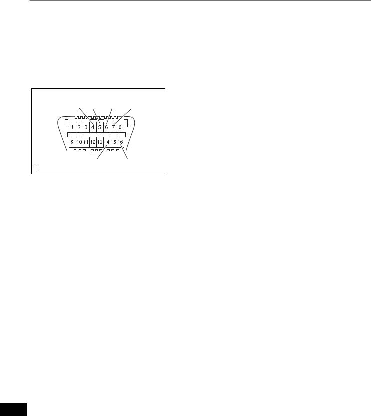
ST–26 |
2GR-FE STARTING – SMART KEY SYSTEM |
|
DIAGNOSIS SYSTEM
|
|
1. |
DESCRIPTION |
|
|
|
(a) Push-button start function data and the Diagnostic |
|
|
|
Trouble Codes (DTCs) can be read through the |
|
|
|
Data Link Connector 3 (DLC3) of the vehicle. When |
|
|
|
the function seems to be malfunctioning, use the |
|
|
|
intelligent tester to check for malfunctions and |
|
|
|
perform repairs. |
|
|
2. |
CHECK DLC3 |
CG |
SG CANH |
SIL |
HINT: |
The ECU uses ISO 15765-4 communication protocol. |
|||
|
|
|
The terminal arrangement of the DLC3 complies with |
|
|
|
SAE J1962 and matches the ISO 15765-4 format. |
|
CANL |
BAT |
|
|
|
H100769E16 |
|
Symbols (Terminal No.) |
Terminal Description |
Condition |
Specified Condition |
|
|
|
|
|
|
CG (4) - Body ground |
Chassis ground |
Always |
Below 1 Ω |
|
|
|
|
|
|
SG (5) - Body ground |
Signal ground |
Always |
Below 1 Ω |
|
|
|
|
|
|
SIL (7) - SG (5) |
Bus "+" line |
During transmission |
Pulse generation |
|
|
|
|
|
|
BAT (16) - Body ground |
Battery positive |
Always |
10 to 14 V |
|
|
|
|
|
|
CANH (6) |
- CANL (14) |
CAN bus line |
Engine Switch OFF* |
56 to 69 Ω |
CANH (6) |
- CG (4) |
HIGH-level CAN bus line |
Engine Switch OFF* |
200 Ω or more |
CANL (14) - CG (4) |
LOW-level CAN bus line |
Engine Switch OFF* |
200 Ω or more |
|
CANH (6) |
- BAT (16) |
HIGH-level CAN bus line |
Engine Switch OFF* |
6 kΩ or more |
CANL (14) - BAT (16) |
LOW-level CAN bus line |
Engine Switch OFF* |
6 kΩ or more |
|
NOTICE:
*: Before measuring the resistance, leave the vehicle as is for at least 1 minute and do not operate the engine switch, any other switches or the doors.
If the result is not as specified, the DLC3 may have a malfunction. Repair or replace the harness and connector.
ST

2GR-FE STARTING – SMART KEY SYSTEM |
ST–27 |
|
CAN VIM |
DLC3 |
Intelligent Tester |
C131977E12 |
CAN VIM |
DLC3 |
Intelligent Tester |
C131977E12 |
HINT:
Connect the cable of the intelligent tester to the DLC3, turn the engine switch on (IG) and attempt to use the tester. If the display indicates that a communication error has occurred, there is a problem either with the vehicle or with the tester.
•If communication is normal when the tester is connected to another vehicle, inspect the DLC3 of the original vehicle.
•If communication is still not possible when the tester is connected to another vehicle, the problem may be in the tester itself. Consult the Service Department listed in the tester's instruction manual.
3.INSPECT BATTERY VOLTAGE Standard voltage:
11 to 14 V
If the voltage is below 11 V, recharge or replace the battery before proceeding.
DTC CHECK / CLEAR
1.CHECK DTC
(a)Connect the intelligent tester to the DLC3.
(b)Turn the engine switch on (IG).
(c)Enter the following menu items: DIAGNOSIS / ENHANCED OBD II / DTC INFO / CURRENT CODES.
(d)Read the DTC by following the prompts on the tester screen.
HINT:
Refer to the intelligent tester operator's manual for further details.
2.CLEAR DTC
(a)Connect the intelligent tester to the DLC3.
(b)Turn the engine switch on (IG).
(c)Enter the following menu items: DIAGNOSIS / ENHANCED OBD II / DTC INFO / CLEAR CODES.
(d)Erase the DTC by following the directions on the
tester screen.
HINT:
Refer to the intelligent tester operator's manual for further details.
ST

ST–28 |
2GR-FE STARTING – SMART KEY SYSTEM |
|
DATA LIST / ACTIVE TEST
1. READ DATA LIST
HINT:
Using the intelligent tester to read the Data List allows the values or states of switches, sensors, actuators and other items to be read without removing any parts. This non-intrusive inspection can be very useful as intermittent conditions or signals may be discovered before parts or wiring is disturbed. Reading the DATA LIST information early in troubleshooting is one way to save diagnostic time.
(a) Connect the intelligent tester (with CAN VIM) to the
|
|
|
|
DLC3. |
|
|
|
|
|
|
When using the intelligent tester with the engine |
||
|
|
|
|
switch off, turn on and off any of the door courtesy |
||
|
|
|
|
light switches repeatedly at 1.5 or less second |
||
|
|
|
|
intervals until communication between the tester |
||
|
|
|
|
and vehicle starts. |
|
|
|
|
|
(b) Turn the engine switch on (IG). |
|||
|
|
|
(c) Enter the following menus: DIAGNOSIS / |
|||
|
|
|
|
ENHANCED OBD II / DATA LIST. |
||
|
|
MAIN BODY: |
(d) Read the DATA LIST. |
|
||
|
|
|
|
|
||
|
|
Item |
Measurement Item / Display |
Normal Condition |
Diagnostic Note |
|
|
|
(Range) |
||||
|
|
|
|
|
||
|
|
|
|
|
|
|
|
|
ACC SW |
Engine switch on (ACC) / ON or |
ON: Engine switch on (ACC) |
- |
|
|
|
OFF |
OFF: Engine switch off |
|||
|
|
|
|
|||
|
|
|
|
|
|
|
|
|
IG SW |
Engine switch on (IG) / ON or |
ON: Engine switch on (IG) |
- |
|
|
|
OFF |
OFF: Engine switch off |
|||
|
|
|
|
|||
|
|
|
|
|
|
|
|
|
SHIFT P SIG |
Shift P position signal / ON or |
ON: Shift position is P |
- |
|
|
|
OFF |
OFF: Shift position is not P |
|||
|
|
|
|
|||
|
|
|
|
|
|
|
|
|
STR UNLOCK SW |
Steering lock condition / ON or |
ON: Steering is unlocked |
- |
|
|
|
OFF |
OFF: Steering is locked |
|||
|
|
|
|
|||
|
|
|
|
|
|
|
|
|
STOP LAMP SW |
Stop light switch / ON or OFF |
ON: Brake pedal depressed |
- |
|
|
|
OFF: Brake pedal released |
||||
|
|
|
|
|
||
|
|
|
|
|
|
|
|
|
STSW1 |
Start switch 1 / ON or OFF |
ON: Engine switch is pushed |
- |
|
|
|
OFF: Engine switch is not pushed |
||||
|
|
|
|
|
||
|
|
|
|
|
|
|
|
|
START SW2 |
Start switch 2 / ON or OFF |
ON: Engine switch is pushed |
- |
|
|
|
OFF: Engine switch is not pushed |
||||
|
|
|
|
|
||
|
|
|
|
|
|
|
|
|
|
|
ON: Shift position is P or N |
|
|
|
|
N SW / C SW |
Neutral start switch / ON or OFF |
OFF: Shift position is neither P |
- |
|
|
|
|
|
nor N |
|
|
|
|
|
|
|
|
|
|
|
|
|
ON: Engine switch on (IG) or |
|
|
|
|
RATCH CIRCUIT |
Ratch circuit / ON or OFF |
engine running |
- |
|
|
|
OFF: Engine switch off or on |
||||
|
|
|
|
|
||
|
|
|
|
(ACC) |
|
|
|
|
|
|
|
|
|
|
|
IG1 RELAY MON1 |
IG1 outer relay monitor / ON or |
ON: Engine switch on (IG) |
- |
|
|
|
OFF |
OFF: Engine switch off |
|||
ST |
|
|
|
|||
|
|
|
|
|
||
|
IG1 RELAY MON2 |
IG1 inner relay monitor / ON or |
ON: Engine switch on (IG) |
- |
||
|
||||||
|
|
|
OFF |
OFF: Engine switch off |
|
|
|
|
IG2 RELAY MON1 |
IG2 outer relay monitor / ON or |
ON: Engine switch on (IG) |
- |
|
|
|
OFF |
OFF: Engine switch off |
|||
|
|
|
|
|||
|
|
|
|
|
|
|
|
|
IG2 RELAY MON2 |
IG2 inner relay monitor / ON or |
ON: Engine switch on (IG) |
- |
|
|
|
OFF |
OFF: Engine switch off |
|||
|
|
|
|
|||
|
|
|
|
|
|
|
|
|
|
STARTER relay monitor / ON or |
ON: Engine is cranking |
Engine is cranking with engine |
|
|
|
ST RELAY MON |
switch on (IG) and shift lever in P |
|||
|
|
OFF |
OFF: Engine is not cranking |
|||
|
|
|
or N |
|||
|
|
|
|
|
||
|
|
|
|
|
|
|

|
2GR-FE STARTING – SMART KEY SYSTEM |
ST–29 |
||
|
|
|||
|
|
|
|
|
Item |
Measurement Item / Display |
Normal Condition |
Diagnostic Note |
|
(Range) |
||||
|
|
|
||
|
|
|
|
|
ST REQUEST SIG |
Starter request signal monitor / |
ON: ST relay is ON |
Engine switch pressed and held |
|
ON or OFF |
OFF: ST relay is OFF |
with shift lever in P or N |
||
|
||||
|
|
|
|
|
ACC RELAY MON |
ACC relay monitor / ON or OFF |
ON: Engine switch on (ACC) |
- |
|
OFF: Engine switch off |
||||
|
|
|
||
|
|
|
|
|
ACC CUT SIG |
ACC relay cut signal / ON or OFF |
ON: Engine is cranking |
- |
|
OFF: Engine is not cranking |
||||
|
|
|
||
|
|
|
|
|
E/G COND |
Engine condition / STOP or RUN |
STOP: Engine is stopped |
- |
|
RUN: Engine is running |
||||
|
|
|
||
|
|
|
|
|
VEHICLE SPD SIG |
Vehicle speed signal / STOP or |
STOP: Vehicle is stopped |
- |
|
RUN |
RUN: Vehicle is running |
|||
|
|
|||
|
|
|
|
|
|
|
ALL: All relays are OFF |
|
|
|
Power supply condition / ALL, |
ACC ON: ACC relay is ON |
- |
|
PWR COND |
IG1: IG1 relay is ON |
|||
ACC ON, IG1 IG2, ST ON |
||||
|
IG2: IG2 relay is ON |
|
||
|
|
|
||
|
|
ST ON: ST request signal is ON |
|
|
|
|
|
|
|
READY SIG |
Ready Signal / ON or OFF or |
|
- |
|
Unknown |
|
|||
|
|
|
||
|
|
|
|
|
COM ENTRY&STRT |
Communication for certification |
OK: Communication |
- |
|
ECU / OK or STOP |
STOP: No communication |
|||
|
|
|||
|
|
|
|
|
2.PERFORM ACTIVE TEST
HINT:
Performing the intelligent tester's ACTIVE TEST allows the relay, VSV, actuator and other items to be operated without removing any parts. Performing the ACTIVE TEST early in troubleshooting is one way to save time. The DATA LIST can be displayed during the ACTIVE TEST.
(a)Connect the intelligent tester to the DLC3
(b)Turn the engine switch on (IG).
(c)Enter the following menus: DIAGNOSIS / ENHANCED OBD II / ACTIVE TEST.
(d)Perform the ACTIVE TEST according to the display on the tester.
MAIN BODY:
Item |
Test Details |
Diagnostic Note |
|
|
|
LIGHTING IND |
Indicator for lighting ON / OFF |
- |
|
|
|
IND CONDITION |
Engine switch indicator Green / Amber / No |
- |
|
Sig |
|
|
|
|
STR LOCK PWR |
Power supply for steering lock ECU ON / OFF |
- |
|
|
|
ST

ST–30 |
2GR-FE STARTING – SMART KEY SYSTEM |
|
DIAGNOSTIC TROUBLE CODE CHART
PUSH-BUTTON START FUNCTION:
|
|
DTC No. |
Detection Item |
|
Trouble Area |
See page |
|
|
|
|
|
|
|
|
|
B2271 |
Ignition Hold Monitor Malfunction |
1. AM2 fuse |
ST-31 |
|
|
|
|
|
2. |
Main body ECU (Instrument |
|
|
|
|
|
panel J/B) |
|
|
|
|
|
|
3. |
Wire harness or connector |
|
|
|
|
|
|
|
|
|
|
B2272 |
Ignition 1 Monitor Malfunction |
1. IG1 relay |
ST-34 |
|
|
|
|
|
2. |
Main body ECU (Instrument |
|
|
|
|
|
panel J/B) |
|
|
|
|
|
|
3. |
Wire harness or connector |
|
|
|
|
|
|
|
|
|
|
B2273 |
Ignition 2 Monitor Malfunction |
1. IG2 relay |
ST-39 |
|
|
|
|
|
2. |
Main body ECU (Instrument |
|
|
|
|
|
panel J/B) |
|
|
|
|
|
|
3. |
Wire harness or connector |
|
|
|
|
|
|
|
|
|
|
B2274 |
ACC Monitor Malfunction |
1. ACC relay |
ST-43 |
|
|
|
|
|
2. |
Main body ECU (Instrument |
|
|
|
|
|
panel J/B) |
|
|
|
|
|
|
3. |
Wire harness or connector |
|
|
|
|
|
|
|
|
|
|
B2275 |
STSW Monitor Malfunction |
1. ECM |
ST-48 |
|
|
|
|
|
2. |
Main body ECU (Instrument |
|
|
|
|
|
panel J/B) |
|
|
|
|
|
|
3. |
Wire harness or connector |
|
|
|
|
|
|
|
|
|
|
B2276 |
ACCR Signal Circuit Malfunction |
1. Main body ECU (Instrument |
ST-51 |
|
|
|
|
|
panel J/B) |
|
|
|
|
|
|
2. ECM |
|
|
|
|
|
|
3. |
Wire harness or connector |
|
|
|
|
|
|
|
|
|
|
B2277 |
Detecting Vehicle Submersion |
Main body ECU (Instrument panel |
ST-54 |
|
|
|
|
|
J/B) |
|
|
|
|
|
|
|
|
|
|
|
B2278 |
Engine Switch Circuit Malfunction |
1. Engine switch |
ST-55 |
|
|
|
|
|
2. |
Main body ECU (Instrument |
|
|
|
|
|
panel J/B) |
|
|
|
|
|
|
3. |
Wire harness or connector |
|
|
|
|
|
|
|
|
|
|
B2281 |
"P" Signal Malfunction |
1. Main body ECU (Instrument |
ST-60 |
|
|
|
|
|
panel J/B) |
|
|
|
|
|
|
2. |
Shift lock control ECU |
|
|
|
|
|
3. |
Wire harness or connector |
|
|
|
|
|
|
|
|
|
|
B2282 |
Vehicle Speed Signal Malfunction |
1. CAN communication system |
ST-63 |
|
|
|
|
|
2. |
Combination meter system |
|
|
|
|
|
3. |
Main body ECU (Instrument |
|
|
|
|
|
panel J/B) |
|
|
|
|
|
|
4. |
Wire harness or connector |
|
|
|
|
|
|
|
|
|
|
B2283 |
Vehicle Speed Sensor |
1. B2282 detection area |
ST-69 |
|
|
|
|
Malfunction |
2. Combination meter |
|
|
|
|
|
|
3. |
Speed sensor |
|
|
|
|
|
4. |
Skid control ECU |
|
|
|
|
|
5. |
Main body ECU (Instrument |
|
|
|
|
|
panel J/B) |
|
|
|
|
|
|
6. |
Wire harness or connector |
|
|
|
|
|
|
|
|
|
|
B2284 |
Brake Signal Malfunction |
1. Stop light switch |
ST-72 |
|
|
|
|
|
2. |
CAN communication system |
|
|
|
|
|
3. ECM |
|
|
|
|
|
|
4. |
Main body ECU (Instrument |
|
ST |
|
|
|
panel J/B) |
|
|
|
|
|
5 Wire harness or connector |
|
||
|
|
|
|
|
|
|
|
|
B2285 |
Steering Lock Position Signal |
1. Main body ECU (Instrument |
ST-77 |
|
|
|
|
Circuit Malfunction |
panel J/B) |
|
|
|
|
|
|
2. |
Steering lock ECU |
|
|
|
|
|
3. |
Wire harness or connector |
|
|
|
|
|
|
|
|
|
|
B2286 |
Runnable Signal Malfunction |
1. CAN communication system |
ST-81 |
|
|
|
|
|
2. ECM |
|
|
|
|
|
|
3. |
Main body ECU (Instrument |
|
|
|
|
|
panel J/B) |
|
|
|
|
|
|
4. |
Wire harness or connector |
|
|
|
|
|
|
|
|
 Loading...