


2GR-FE ENGINE CONTROL SYSTEM – SFI SYSTEM |
ES–1 |
|
SFI SYSTEM
PRECAUTION
NOTICE:
•Perform the RESET MEMORY (AT) initialization operation after replacing the automatic transmission assembly, engine assembly or ECM (See page AX-25).
•Perform REGISTRATION (VIN registration) when replacing the ECM (See page ES-20).
ES
|
|
ES–2 |
2GR-FE ENGINE CONTROL SYSTEM – SFI SYSTEM |
||
|
|
|
|||
|
|
|
|
DEFINITION OF TERMS |
|
|
|
|
|
|
|
|
|
Terms |
|
Definition |
|
|
|
|
|
|
|
|
|
Monitor Description |
|
Description of what ECM monitors and how to detect malfunctions (monitoring purpose and |
|
|
|
|
|
its details). |
|
|
|
|
|
|
|
|
|
Related DTCs |
|
A group of diagnostic trouble codes that are output by ECM based on the same |
|
|
|
|
|
malfunction detection logic. |
|
|
|
|
|
|
|
|
|
Typical Enabling Condition |
|
Preconditions that allow ECM to detect malfunctions. |
|
|
|
|
|
With all preconditions satisfied, ECM sets DTC when monitored value(s) exceeds |
|
|
|
|
|
malfunction threshold(s). |
|
|
|
|
|
|
|
|
|
Sequence of Operation |
|
Order of monitor priority, applied if multiple sensors and components are involved in single |
|
|
|
|
|
malfunction detection process. |
|
|
|
|
|
Each sensor and component monitored in turn and not monitored until previous detection |
|
|
|
|
|
operation is completed. |
|
|
|
|
|
|
|
|
|
Required Sensor/Components |
|
Sensors and components used by ECM to detect each malfunction. |
|
|
|
|
|
|
|
|
|
Frequency of Operation |
|
Number of times ECM checks for each malfunction during each driving cycle. |
|
ES |
|||||
|
|
|
"Once per driving cycle" means that ECM checks for malfunctions only once in single |
||
|
|
|
driving cycle. |
||
|
|
|
|||
|
|
|
|
"Continuous" means that ECM checks for malfunctions whenever enabling conditions are |
|
|
|
|
|
met. |
|
|
|
|
|
|
|
|
|
Duration |
|
Minimum time for which ECM must detect continuous deviation in monitored value(s) in |
|
|
|
|
|
order to set DTC. Timing begins when Typical Enabling Conditions are met. |
|
|
|
|
|
|
|
|
|
Malfunction Thresholds |
|
Value, beyond which, ECM determines malfunctions exist and sets DTCs. |
|
|
|
|
|
|
|
|
|
MIL Operation |
|
Timing of MIL illumination after a malfunction is detected. |
|
|
|
|
|
"Immediate" means that ECM illuminates MIL as soon as a malfunction is detected. |
|
|
|
|
|
"2 driving cycle" means that ECM illuminates MIL if the same malfunction is detected twice |
|
|
|
|
|
during next sequential driving cycle. |
|
|
|
|
|
|
|

2GR-FE ENGINE CONTROL SYSTEM – SFI SYSTEM |
ES–3 |
|
PARTS LOCATION
ECM |
|
|
|
MASS AIR FLOW METER |
|
|
ENGINE ROOM R/B |
|
|
- EFI RELAY |
ES |
|
- A/F RELAY |
|
|
|
|
|
- C/OPN RELAY |
|
|
- ST RELAY |
|
PURGE VSV |
- ST CUT RELAY |
|
|
- IG2 RELAY |
|
|
CANISTER |
|
|
FUEL PUMP |
|
HEATED OXYGEN SENSOR |
|
|
(BANK 1 SENSOR 2) |
|
|
ACTIVE MOUNT CONTROL VSV |
|
|
HEATED OXYGEN SENSOR |
|
|
(BANK 2 SENSOR 2) |
|
|
|
A134870E01 |
|

ES–4 |
2GR-FE ENGINE CONTROL SYSTEM – SFI SYSTEM |
|
ES |
COMBINATION METER |
|
|
DLC3 |
|
INSTRUMENT PANEL J/B |
|
- IGN FUSE |
|
- STOP FUSE |
ACCELERATOR PEDAL |
|
STOP LIGHT SWITCH |
|
A139510E01 |

2GR-FE ENGINE CONTROL SYSTEM – SFI SYSTEM |
ES–5 |
|
|
|
|
VVT SENSOR (BANK 1 INTAKE SIDE) |
|
VVT SENSOR FOR INTAKE CAMSHAFT |
|
(BANK 2) |
|
CAMSHAFT TIMING OIL CONTROL VALVE ASSEMBLY |
|
(BANK 1 INTAKE SIDE) |
|
CAMSHAFT TIMING OIL CONTROL VALVE ASSEMBLY |
|
(BANK 2 INTAKE SIDE) |
|
ENGINE COOLANT
IGNITION COIL WITH IGNITER |
TEMPERATURE SENSOR |
|
|
FUEL INJECTOR |
|
ES
AIR FUEL RATIO SENSOR (BANK 2 SENSOR 1)
VVT SENSOR FOR EXHAUST CAMSHAFT (BANK 2)
CRANKSHAFT POSITION SENSOR
VVT SENSOR FOR EXHAUST CAMSHAFT (BANK 1)
AIR FUEL RATIO SENSOR (BANK 1 SENSOR 1)
CAMSHAFT TIMING OIL CONTROL VALVE ASSEMBLY
CAMSHAFT TIMING OIL CONTROL VALVE ASSEMBLY
(BANK 2 EXHAUST SIDE)
A114586E05

ES–6 |
2GR-FE ENGINE CONTROL SYSTEM – SFI SYSTEM |
|
THROTTLE BODY |
(THROTTLE POSITION |
SENSOR) |
ES |
ACIS ACTUATOR |
KNOCK SENSOR (BANK 1) |
KNOCK SENSOR (BANK 2) |
A114543E04 |
2GR-FE ENGINE CONTROL SYSTEM – SFI SYSTEM |
ES–7 |
|
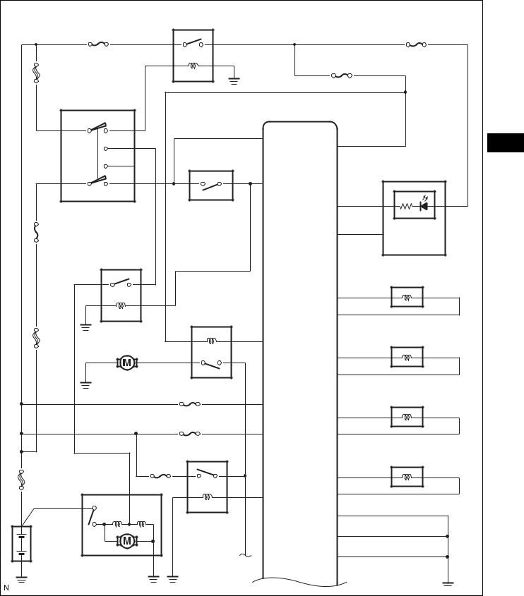
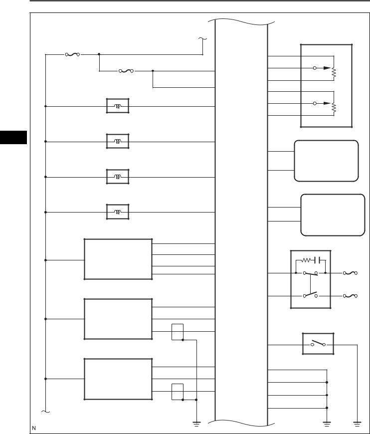
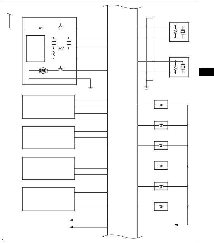
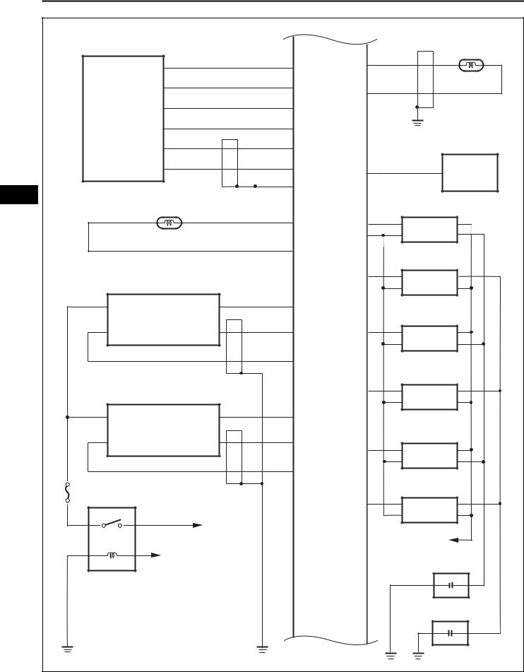
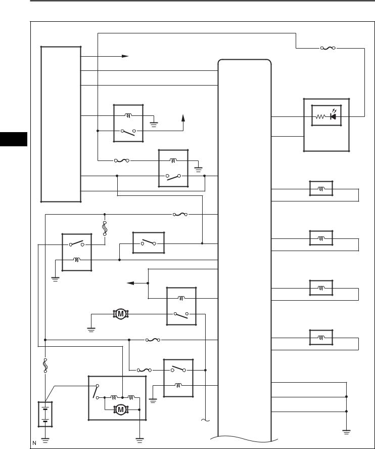
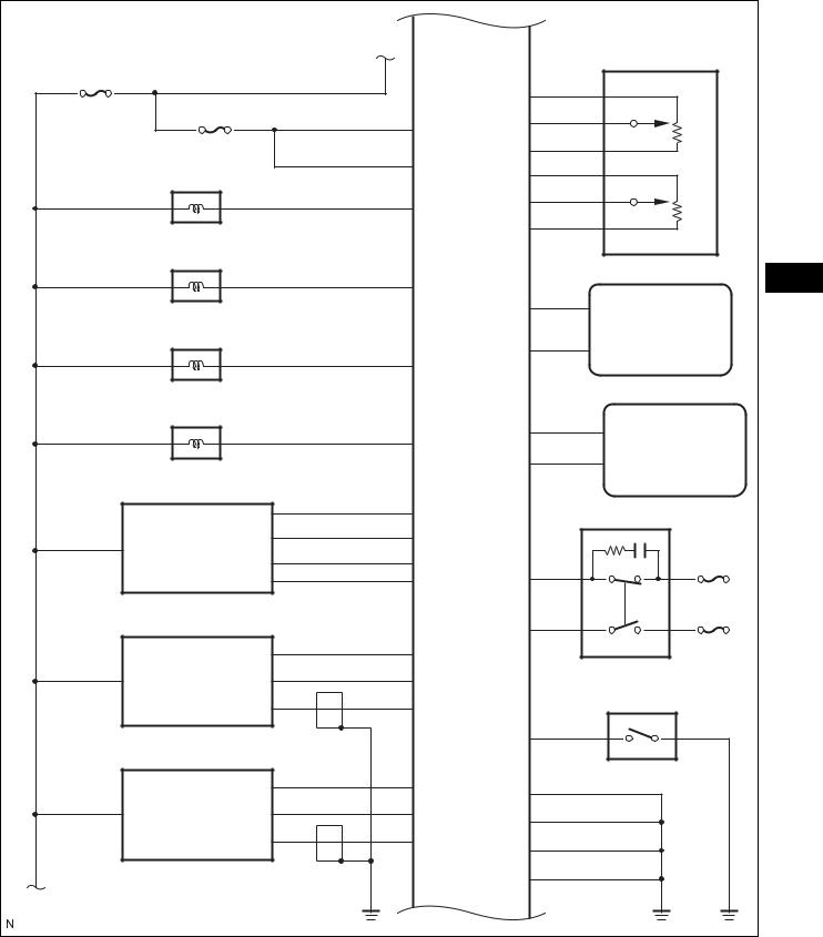
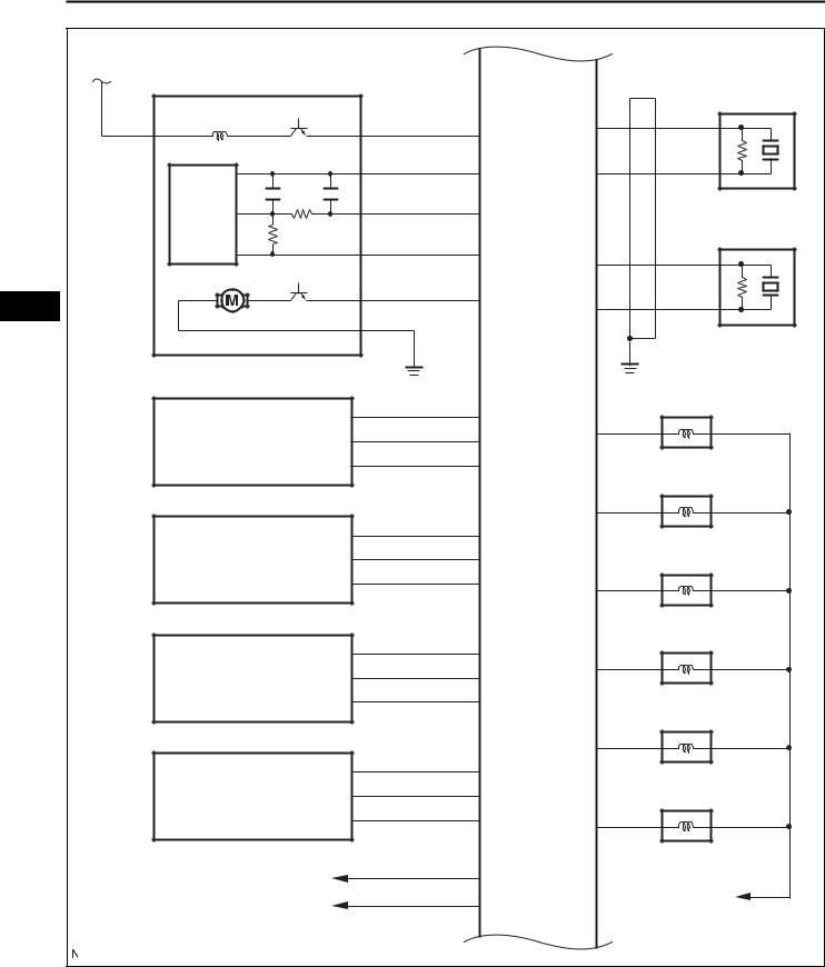
SYSTEM DIAGRAM
1.Without Smart Key System:
|
|
IG2 |
|
|
GAUGE No. 2 |
|
IG2 |
|
|
|
|
|
|
|
|
|
|
ST/AM2 |
|
|
|
|
IGN |
|
|
|
|
|
|
|
IG SW |
|
|
|
|
AM2 |
|
|
ECM |
|
|
IG2 |
|
|
|
ES |
|
|
ST2 |
|
NSW |
IGSW |
|
|
|
|
|||
|
IG1 |
PNP SW |
|
||
|
|
|
Combination Meter |
||
AM1 |
ST1 |
|
|
|
|
|
STA |
|
|
||
|
|
|
|
|
|
|
|
|
|
W |
|
AM1 |
|
|
|
SPD |
MIL |
|
ST |
|
|
|
VVT OCV (Intake Side RH) |
|
|
|
|
|
|
|
|
|
|
OC1+ |
|
|
|
C/OPN |
|
OC1- |
|
ALT |
Fuel Pump |
|
|
|
VVT OCV (Intake Side LH) |
|
FC |
|
|
||
|
|
|
|
OC2+ |
|
|
|
|
|
OC2- |
|
|
|
ETCS |
|
|
VVT OCV (Exhaust Side RH) |
|
|
|
+BM |
OE1+ |
|
|
|
EFI No. 1 |
|
|
|
|
|
BATT |
OE1- |
|
|
|
|
|
|
||
|
|
EFI |
|
|
VVT OCV (Exhaust Side LH) |
|
EFI MAIN |
|
|
|
|
FL MAIN |
|
|
|
OE2+ |
|
|
|
|
MREL |
OE2- |
|
|
|
|
|
E02 |
|
Battery |
|
|
|
E05 |
|
|
|
|
|
|
|
|
Starter |
|
A |
E1 |
|
|
|
|
|
||
|
|
|
|
|
A137635E02 |
ES–8 |
2GR-FE ENGINE CONTROL SYSTEM – SFI SYSTEM |
|
A |
ECM |
|
APP Sensor |
|
EFI No. 3 |
|
|
|
|
EFI No. 2 |
|
VCP2 |
|
|
|
VPA2 |
|
||
|
+B |
|
||
|
|
|
|
|
|
+B2 |
EPA2 |
|
|
|
VCPA |
|
||
|
|
|
||
|
AICV |
|
VPA |
|
|
|
|
|
|
VSV for ACIS |
|
|
EPA |
|
|
|
|
|
|
ES |
PRG |
|
|
Transmission |
VSV for EVAP System |
|
CAN+ |
||
|
Control ECU |
|||
|
|
|
||
|
|
|
|
|
|
ACIS |
CAN- |
|
|
|
|
|
|
|
VSV for ACIS |
|
|
|
|
|
|
|
IMO |
Transponder Key |
|
ACM |
|
ECU |
|
|
|
|
||
VSV for Active Control Mount System |
|
|
IMI |
|
|
|
|
|
|
|
THA |
|
|
Stop Light SW |
|
|
|
|
|
MAF Meter |
E2G |
|
|
|
|
VG |
|
STP |
STOP |
|
ETHA |
|
|
|
|
|
ST1- |
IGN |
|
|
|
|
||
HO2 Sensor |
HT1B |
|
|
|
(Bank 1 Sensor 2) |
EX1B |
|
|
Power Steering Oil Pressure SW |
|
|
|
||
|
OX1B |
|
|
|
|
|
PSW |
|
|
HO2 Sensor |
HT2B |
|
E04 |
|
(Bank 2 Sensor 2) |
EX2B |
|
E01 |
|
|
|
|
||
|
|
|
|
|
|
OX2B |
|
E03 |
|
|
|
|
|
|
|
|
ME01 |
|
|
B |
|
|
|
|
|
|
|
|
A137631E02 |
2GR-FE ENGINE CONTROL SYSTEM – SFI SYSTEM |
ES–9 |
|
B |
Canister Pump Module |
ECM |
|
|
|
|
VPMP |
KNK1 |
|
|
|
|
|
|
|
|
EPPM |
EKNK |
|
|
|
PPMP |
|
Knock Sensor (Bank 1) |
|
|
|
|
|
|
|
VCPP |
KNK2 |
|
|
|
|
|
|
|
|
MPMP |
EKN2 |
ES |
|
|
|
||
|
|
|
|
Knock Sensor (Bank 2) |
|
VVT Sensor |
VV1+ |
#10 |
|
|
(Bank 1 Intake Side) |
VV1- |
|
|
|
|
|
|
|
|
|
VCV1 |
|
No. 1 Fuel Injector |
|
|
|
#20 |
|
|
VVT Sensor |
VV2+ |
|
No. 2 Fuel Injector |
|
(Bank 2 Intake Side) |
VV2- |
|
|
|
|
|
|
|
|
|
VCV2 |
#30 |
|
|
|
|
|
|
|
|
|
|
No. 3 Fuel Injector |
|
VVT Sensor |
EV1+ |
#40 |
|
|
(Bank 1 Exhaust Side) |
EV1- |
|
|
|
|
|
|
|
|
|
VCE1 |
|
No. 4 Fuel Injector |
|
|
|
|
|
|
|
|
#50 |
|
|
VVT Sensor |
EV2+ |
|
No. 5 Fuel Injector |
|
(Bank 2 Exhaust Side) |
EV2- |
|
|
|
|
|
|
|
|
|
VCE2 |
#60 |
|
|
|
|
|
|
|
|
|
|
No. 6 Fuel Injector |
|
To Main Body ECU |
CANH |
|
To IG2 Relay |
|
CANL |
|
||
|
|
|
||
|
|
|
|
|
|
|
|
|
A137632E02 |
ES–10 |
2GR-FE ENGINE CONTROL SYSTEM – SFI SYSTEM |
|
|
|
|
|
|
Crankshaft Position Sensor |
|
|
|
ECM |
|
|
|
|
|
VTA1 |
NE+ |
|
|
|
|
|
|
|
|
|
Throttle Body |
VCTA |
NE- |
|
|
|
|
|
||
|
|
Assembly |
VTA2 |
|
|
|
|
|
ETA |
|
|
|
|
|
M+ |
|
|
|
|
|
M- |
TC |
DLC3 |
ES |
|
|
GE01 |
|
|
|
ECT Sensor |
|
|
Ignition Coil (No. 1) |
|
|
|
|
THW |
IGT1 |
|
|
|
|
|
IGF1 |
|
|
|
|
ETHW |
|
Ignition Coil (No. 2) |
|
|
|
|
IGT2 |
|
|
|
A/F Sensor |
HA1A |
|
Ignition Coil (No. 3) |
|
|
(Bank 1 Sensor 1) |
|
|
|
|
|
|
A1A+ |
IGT3 |
|
|
|
|
A1A- |
|
Ignition Coil (No. 4) |
|
|
|
|
IGT4 |
|
|
|
A/F Sensor |
HA2A |
|
Ignition Coil (No. 5) |
|
|
(Bank 2 Sensor 1) |
|
||
|
|
|
|
|
|
|
|
|
A2A+ |
IGT5 |
|
|
|
|
|
|
|
|
|
|
A2A- |
|
Ignition Coil (No. 6) |
|
|
|
|
|
|
|
A/F |
A/F |
|
IGT6 |
|
|
|
|
|
||
|
|
|
|
|
|
|
|
To Battery |
|
|
|
|
|
|
|
|
To IG2 Relay |
|
|
To EFI Relay |
|
|
Noise Filter (RH Side) |
|
|
|
|
|
Noise Filter (LH Side) |
|
|
|
|
|
A137633E02 |
2GR-FE ENGINE CONTROL SYSTEM – SFI SYSTEM |
ES–11 |
|
GAUGE No. 1 |
ECM |
Transmission Control SW To IG1 Relay |
|
|
|
To IG1 Relay |
|
S |
|
|
|
Park / Neutral Position SW |
|
ECU IG No. 2 |
|
SFTD |
|
|
P |
SFTU |
|
|
|
|
R |
Spiral Cable |
|
|
|
|
|
Cruise Control SW |
|
N |
|
|
D |
ES |
|
|
|
Transmission Control |
|
|
ECU |
|
|
|
|
CCS |
|
|
A137634E02 |
ES–12 |
2GR-FE ENGINE CONTROL SYSTEM – SFI SYSTEM |
|
2.With Smart Key System:
Main Body ECU |
|
|
|
GAUGE No. 2 |
|
|
|
|
|
ACC |
|
ECM |
|
|
To ECU-ACC Fuse |
|
|
||
STSW |
|
STSW |
|
|
ACCR |
|
ACCR |
|
Combinatiion Meter |
|
IG2 |
To IG2 Fuse |
|
|
|
|
|
|
|
IG2D |
|
|
W |
|
ES |
|
ST CUT |
SPD |
MIL |
|
|
|
||
|
IGN |
|
|
|
STR |
|
STAR |
|
VVT OCV (Intake Side RH) |
|
|
|
||
STR2 |
|
|
OC1+ |
|
|
|
ETCS |
OC1- |
|
|
|
|
|
|
|
|
+BM |
|
VVT OCV (Intake Side LH) |
ST |
ST/AM2 |
PNP SW |
|
|
|
|
|||
|
|
NSW |
OC2+ |
|
|
|
OC2- |
|
|
|
|
|
|
|
|
|
STA |
|
|
|
|
IGSW |
|
VVT OCV (Exhaust Side RH) |
|
To IGN Fuse |
C/OPN |
OE1+ |
|
|
|
|
|
|
|
Fuel Pump |
FC |
OE1- |
|
|
|
|
|
VVT OCV (Exhaust Side LH) |
|
|
EFI No. 1 |
OE2+ |
|
|
|
BATT |
|
|
|
|
|
|
|
|
|
EFI |
OE2- |
|
|
|
|
|
|
FL MAIN |
EFI MAIN |
|
|
|
|
|
|
|
|
|
|
MREL |
E02 |
|
|
|
|
|
|
|
|
|
E05 |
|
Battery |
|
|
E1 |
|
|
Starter |
A |
|
|
|
|
|
|
A137630E02 |
2GR-FE ENGINE CONTROL SYSTEM – SFI SYSTEM |
ES–13 |
|
A |
ECM |
|
APP Sensor |
|
EFI No. 3 |
|
|
|
|
EFI No. 2 |
|
VCP2 |
|
|
|
VPA2 |
|
||
|
+B |
|
||
|
|
|
|
|
|
+B2 |
EPA2 |
|
|
|
VCPA |
|
||
|
|
|
||
|
AICV |
|
VPA |
|
|
|
|
|
|
VSV for ACIS |
|
|
EPA |
|
|
|
|
|
|
|
PRG |
|
|
ES |
VSV for EVAP System |
|
CAN+ |
Transmission |
|
|
Control ECU |
|||
|
|
|
||
|
|
|
|
|
|
ACIS |
CAN- |
|
|
|
|
|
|
|
VSV for ACIS |
|
|
|
|
|
|
|
IMO |
Transponder Key |
|
ACM |
|
ECU |
|
|
|
|
||
VSV for Active Control Mount System |
|
|
IMI |
|
|
|
|
|
|
|
THA |
|
|
Stop Light SW |
|
|
|
|
|
MAF Meter |
E2G |
|
|
|
|
VG |
|
STP |
STOP |
|
ETHA |
|
|
|
|
|
ST1- |
IGN |
|
|
|
|
||
HO2 Sensor |
HT1B |
|
|
|
(Bank 1 Sensor 2) |
EX1B |
|
|
Power Steering Oil Pressure SW |
|
|
|
||
|
OX1B |
|
|
|
|
|
PSW |
|
|
HO2 Sensor |
HT2B |
|
E04 |
|
(Bank 2 Sensor 2) |
EX2B |
|
E01 |
|
|
|
|
||
|
|
|
|
|
|
OX2B |
|
E03 |
|
|
|
|
|
|
|
|
ME01 |
|
|
B |
|
|
|
|
|
|
|
|
A137631E02 |
ES–14 |
2GR-FE ENGINE CONTROL SYSTEM – SFI SYSTEM |
|
B |
Canister Pump Module |
ECM |
|
|
|
VPMP |
KNK1 |
|
|
|
|
|
|
EPPM |
EKNK |
|
|
PPMP |
Knock Sensor (Bank 1) |
|
|
|
|
|
|
VCPP |
KNK2 |
|
|
|
|
ES |
|
MPMP |
EKN2 |
|
|
||
|
|
|
Knock Sensor (Bank 2) |
|
VVT Sensor |
VV1+ |
#10 |
|
(Bank 1 Intake Side) |
VV1- |
|
|
|
|
|
|
|
VCV1 |
No. 1 Fuel Injector |
|
|
|
#20 |
|
VVT Sensor |
VV2+ |
No. 2 Fuel Injector |
|
(Bank 2 Intake Side) |
VV2- |
|
|
|
|
|
|
|
VCV2 |
#30 |
|
|
|
|
|
|
|
No. 3 Fuel Injector |
|
VVT Sensor |
EV1+ |
#40 |
|
(Bank 1 Exhaust Side) |
EV1- |
|
|
|
|
|
|
|
VCE1 |
No. 4 Fuel Injector |
|
|
|
|
|
|
|
#50 |
|
VVT Sensor |
EV2+ |
No. 5 Fuel Injector |
|
(Bank 2 Exhaust Side) |
EV2- |
|
|
|
|
|
|
|
VCE2 |
#60 |
|
|
|
|
|
|
|
No. 6 Fuel Injector |
|
To Main Body ECU |
CANH |
To IG2 Relay |
|
CANL |
||
|
|
||
|
|
|
|
|
|
|
A137632E02 |

2GR-FE ENGINE CONTROL SYSTEM – SFI SYSTEM |
ES–15 |
|
|
|
|
|
Crankshaft Position Sensor |
|
|
|
ECM |
|
|
|
|
|
VTA1 |
NE+ |
|
|
|
|
|
|
|
|
|
Throttle Body |
VCTA |
NE- |
|
|
|
|
|
|
||
|
Assembly |
VTA2 |
|
|
|
|
|
ETA |
|
|
|
|
|
M+ |
|
|
|
|
|
M- |
TC |
DLC3 |
|
|
|
GE01 |
|
|
|
|
ECT Sensor |
|
|
Ignition Coil (No. 1) |
ES |
|
|
THW |
IGT1 |
|
|
|
|
|
|
||
|
|
|
IGF1 |
|
|
|
|
ETHW |
|
Ignition Coil (No. 2) |
|
|
|
|
IGT2 |
|
|
|
A/F Sensor |
HA1A |
|
Ignition Coil (No. 3) |
|
|
(Bank 1 Sensor 1) |
|
|
|
|
|
|
A1A+ |
IGT3 |
|
|
|
|
A1A- |
|
Ignition Coil (No. 4) |
|
|
|
|
IGT4 |
|
|
|
A/F Sensor |
HA2A |
|
Ignition Coil (No. 5) |
|
|
(Bank 2 Sensor 1) |
|
|
||
|
|
|
|
|
|
|
|
A2A+ |
IGT5 |
|
|
|
|
|
|
|
|
|
|
A2A- |
|
Ignition Coil (No. 6) |
|
|
|
|
|
|
|
A/F |
A/F |
|
IGT6 |
|
|
|
|
|
|
||
|
|
|
|
|
|
|
To Battery |
|
|
|
|
|
|
|
|
To IG2 Relay |
|
|
To EFI Relay |
|
|
Noise Filter (RH Side) |
|
|
|
|
|
Noise Filter (LH Side) |
|
|
|
|
|
|
A137633E02 |

ES–16 |
2GR-FE ENGINE CONTROL SYSTEM – SFI SYSTEM |
|
GAUGE No. 1 |
ECM |
Transmission Control SW To IG1 Relay |
|
|
|
To IG1 Relay |
|
S |
|
|
|
Park / Neutral Position SW |
|
ECU IG No. 2 |
|
SFTD |
|
|
P |
SFTU |
|
|
|
|
R |
Spiral Cable |
|
|
|
|
|
Cruise Control SW |
|
N |
|
|
D |
|
ES |
|
|
Transmission Control |
|
|
ECU |
|
|
|
|
CCS |
|
|
A137634E02 |

2GR-FE ENGINE CONTROL SYSTEM – SFI SYSTEM |
ES–17 |
|
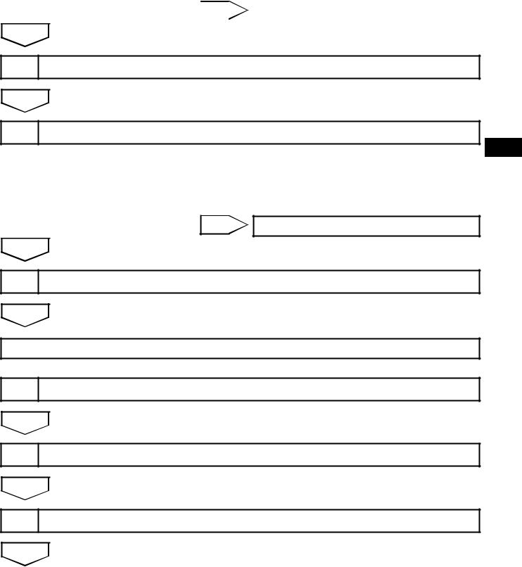
HOW TO PROCEED WITH TROUBLESHOOTING
HINT:
*: Use the intelligent tester.
1VEHICLE BROUGHT TO WORKSHOP
NEXT
2CUSTOMER PROBLEM ANALYSIS
NEXT
3CONNECT INTELLIGENT TESTER TO DLC3*
ES
HINT:
If the display indicates a communication fault in the tester, inspect the DLC3.
NEXT
4 CHECK DTC AND FREEZE FRAME DATA*
HINT:
Record or print DTCs and freeze frame data, if necessary.
NEXT
5CLEAR DTC AND FREEZE FRAME DATA*
NEXT
6CONDUCT VISUAL INSPECTION
NEXT
7SET CHECK MODE DIAGNOSIS*
NEXT
8CONFIRM PROBLEM SYMPTOMS
HINT:
If the engine does not start, perform steps 10 and 12 first.
|
|
ES–18 |
|
2GR-FE ENGINE CONTROL SYSTEM – SFI SYSTEM |
|
|||||
|
|
|
|
|
||||||
|
|
|
|
|
Result |
|
|
|
|
|
|
|
|
|
|
|
|
|
|
|
|
|
|
|
|
|
|
|
|
Result |
|
Proceed to |
|
|
|
|
|
|
|
|
|
||
|
|
|
|
|
Malfunction does not occur |
|
A |
|||
|
|
|
|
|
|
|
|
|
|
|
|
|
|
|
|
|
|
Malfunction occurs |
|
B |
|
|
|
|
|
|
|
|
|
|
|
|
|
|
|
|
|
B |
|
|
|
|
|
|
|
|
|
|
|
GO TO STEP 10 |
|
|||
|
|
|
|
|
|
|
|
|
|
|
|
|
|
|
|
|
|
|
|
|
|
|
|
A |
|
|
|
|
|
|
|
|
|
|
|
|
|
|
|||||
|
|
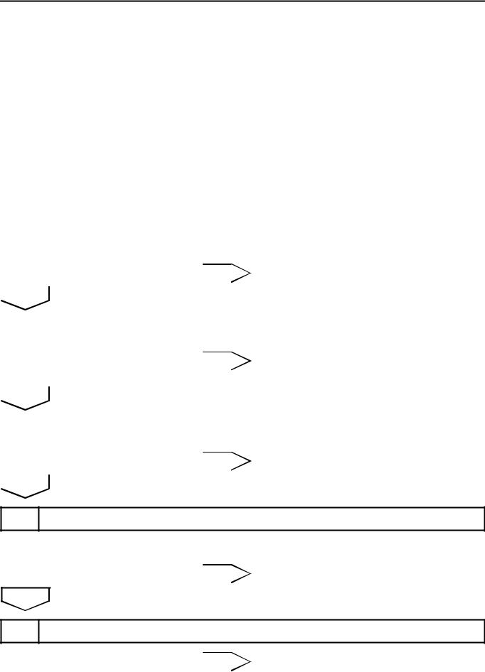
9 |
SIMULATE SYMPTOMS |
|
|
|
|
|||
|
|
|
|
|
|
|
|
|
|
|
|
|
|
|
|
|
|
|
|
|
|
|
|
NEXT |
|
|
|
|
|
|
|
|
|
|
|
|
|
|
|
|
|
|
|
ES |
|
|
|
|
|
|||||
|
10 |
CHECK FOR DTCS* |
|
|
|
|
||||
|
|
|
|
|
||||||
|
|
|
|
|
|
|
|
|
|
|
|
|
|
|
|
Result |
|
|
|
|
|
|
|
|
|
|
|
|
|
|
|
|
|
|
|
|
|
|
|
|
Result |
|
Proceed to |
|
|
|
|
|
|
|
|
|
|
|
|
|
|
|
|
|
|
Trouble code |
|
A |
|
|
|
|
|
|
|
|
|
|
|
|
|
|
|
|
|
|
|
|
No code |
|
B |
|
|
|
|
|
|
|
|
|
|
|
|
|
|
|
|
B |
|
|
|
|
|
|
|
|
|
|
|
GO TO STEP 12 |
|
|||
|
|
|
|
|
|
|
|
|
|
|
|
|
|
|
|
|
|
|
|
|
|
|
|
A |
|
|
|
|
|
|
|
|
|
|
|
|
|
|
|
||||
|
|
11 |
REFER TO DTC CHART |
|
|
|
|
|||
|
|
|
|
|
|
|
|
|
|
|
|
|
|
|
|
|
|
|
|
|
|
|
|
NEXT |
|
|
|
|
|
|
|
|
|
|
|
|
|
|
|
||||
|
|
GO TO STEP 14 |
|
|
|
|
||||
|
|
|
|
|
|
|
||||
|
|
|
|
|
|
|||||
|
|
12 |
CONDUCT BASIC INSPECTION |
|
|
|
|
|||
|
|
|
|
|
|
|
|
|
|
|
|
|
|
|
|
Result |
|
|
|
|
|
|
|
|
|
|
|
|
|
|
|
|
|
|
|
|
|
|
|
|
Result |
|
Proceed to |
|
|
|
|
|
|
|
|
|||
|
|
|
|
|
Malfunctioning parts not confirmed |
|
A |
|||
|
|
|
|
|
|
|
|
|||
|
|
|
|
|
Malfunctioning parts confirmed |
|
B |
|||
|
|
|
|
|
|
|
|
|
|
|
|
|
|
|
|
B |
|
|
|
|
|
|
|
|
|
|
|
GO TO STEP 17 |
|
|||
|
|
|
|
|
|
|
|
|
|
|
|
|
|
|
|
|
|
|
|
|
|
|
|
A |
|
|
|
|
|
|
|
|
|
|
|
|
|||||||
|
|
13 |
REFER TO PROBLEM SYMPTOMS TABLE |
|
||||||
|
|
|
|
|
|
|
|
|
|
|
|
|
|
|
|
Result |
|
|
|
|
|
|
|
|
|
|
|
|
|
|
|
|
|
|
|
|
|
|
|
|
Result |
|
Proceed to |
|
|
|
|
|
|
|
|
|||
|
|
|
|
|
Malfunctioning circuit confirmed |
|
A |
|||
|
|
|
|
|
|
|
|
|
|
|
2GR-FE ENGINE CONTROL SYSTEM – SFI SYSTEM |
ES–19 |
||||
|
|||||
|
|
|
|
|
|
|
|
|
Result |
|
Proceed to |
|
|
|
|
|
|
|
Malfunctioning parts confirmed |
|
B |
||
|
|
|
|
|
|
|
B |
|
|
|
|
|
|
GO TO STEP 17 |
|
||
|
|
|
|
|
|
A
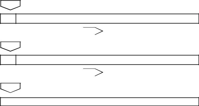
14CHECK ECM POWER SOURCE CIRCUIT
NEXT
15CONDUCT CIRCUIT INSPECTION
Result
ES
Result |
Proceed to |
|
|
Malfunction not confirmed |
A |
|
|
Malfunction confirmed |
B |
|
|
B GO TO STEP 18
A
16 CHECK FOR INTERMITTENT PROBLEMS
NEXT
GO TO STEP 18
17CONDUCT PARTS INSPECTION
NEXT
18IDENTIFY PROBLEM
NEXT
19 ADJUST AND/OR REPAIR
NEXT

ES–20 |
2GR-FE ENGINE CONTROL SYSTEM – SFI SYSTEM |
|
20 CONDUCT CONFIRMATION TEST
NEXT
END
ES
2GR-FE ENGINE CONTROL SYSTEM – SFI SYSTEM |
ES–21 |
|
CHECK FOR INTERMITTENT PROBLEMS
HINT:
Inspect the vehicle's ECM using check mode. Intermittent problems are easier to detect with an intelligent tester when the ECM is in check mode. In check mode, the ECM uses 1 trip detection logic, which is more sensitive to malfunctions than normal mode (default), which uses 2 trip detection logic.
1.Clear the DTCs.
2.Switch the ECM from normal mode to check mode using an intelligent tester (See page ES-49).
3.Perform a simulation test (See page IN-40).
4.Check and wiggle the harness(es), connector(s) and
terminal(s) (See page IN-45). |
ES |
|
ES–22 |
2GR-FE ENGINE CONTROL SYSTEM – SFI SYSTEM |
|
|
|
|
|
|
BASIC INSPECTION |
|
||||
|
|
|
|
|
When the malfunction is not confirmed by the DTC check, |
|||||
|
|
|
|
|
troubleshooting should be carried out in all circuits |
|||||
|
|
|
|
|
considered to be possible causes of the problem. In many |
|||||
|
|
|
|
|
cases, by carrying out the basic engine check shown in the |
|||||
|
|
|
|
|
following flowchart, the location of the problem can be found |
|||||
|
|
|
|
|
quickly and efficiently. Therefore, using this check is essential |
|||||
|
|
|
|
|
when troubleshooting the engine. |
|
||||
|
|
|
|
|
|
|
||||
|
|
1 |
CHECK BATTERY VOLTAGE |
|
|
|
|
|||
|
|
|
|
|
|
|
|
|
|
|
|
|
|
|
|
NOTICE: |
|
|
|
|
|
|
|
|
|
|
Carry out this check with the engine stopped and the |
|||||
|
|
|
|
|
engine switch off. |
|
||||
ES |
|
|
|
|||||||
|
|
|
|
Result |
|
|
|
|
||
|
|
|
|
|
||||||
|
|
|
|
|
|
|
|
|
|
|
|
|
|
|
|
|
|
|
Result |
|
Proceed to |
|
|
|
|
|
|
|
|
|
|
|
|
|
|
|
|
|
|
11 V or more |
|
OK |
|
|
|
|
|
|
|
|
|
|
|
|
|
|
|
|
|
|
|
Below 11 V |
|
NG |
|
|
|
|
|
|
|
|
|
|
|
|
|
|
|
|
|
NG |
|
|
|
|
|
|
|
|
|
|
|
CHARGE OR REPLACE BATTERY |
||||
|
|
|
|
|
|
|
|
|
|
|
|
|
|
|
|
|
|
|
|
|
|
|
|
OK |
|
|
|
|
|
|
|
|
|
|
|
|
|
|
|
||||
|
|
2 |
CHECK WHETHER ENGINE CRANKS |
|
|
|
|
|||
|
|
|
|
|
|
|
|
|
||
|
|
|
|
|
NG |
|
|
|
|
|
|
|
|
|
|
|
PROCEED TO PROBLEM SYMPTOMS |
||||
|
|
|
|
|
|
|
|
TABLE |
|
|
|
|
|
|
|
|
|
|
|||
|
|
|
|
|
|
|
|
|
|
|
|
|
|
|
|
|
|
|
|
|
|
|
|
OK |
|
|
|
|
|
|
|
|
|
|
|
|
|
|
|
||||
|
|
3 |
CHECK WHETHER ENGINE STARTS |
|
|
|
|
|||
|
|
|
|
|
|
|
|
|
|
|
|
|
|
|
|
NG |
|
|
|
|
|
|
|
|
|
|
|
GO TO STEP 6 |
|
|||
|
|
|
|
|
|
|
|
|
|
|
|
|
|
|
|
|
|
|
|
|
|
|
|
OK |
|
|
|
|
|
|
|
|
4 CHECK AIR FILTER
(a)Visually check that the air filter is not excessively contaminated with dirt or oil.
NG |
|
REPLACE AIR FILTER |
|
|
|
OK
5 CHECK IDLING SPEED
NG |
|
TROUBLESHOOT IDLING SPEED AND |
|
|
PROCEED TO NEXT STEP |
|
||
|
|
|
2GR-FE ENGINE CONTROL SYSTEM – SFI SYSTEM |
ES–23 |
|
OK
6 CHECK FUEL PRESSURE
NG |
|
TROUBLESHOOT FUEL PRESSURE AND |
|
|
PROCEED TO NEXT STEP |
|
||
|
|
|
OK
7 CHECK FOR SPARKS
NG |
|
TROUBLESHOOT SPARK AND PROCEED |
|
|
|
ES |
|||||
|
|
TO NEXT STEP |
|
||
|
|||||
|
|
|
|
|
OK
PROCEED TO PROBLEM SYMPTOMS TABLE

ES–24
ES
2GR-FE ENGINE CONTROL SYSTEM – SFI SYSTEM
REGISTRATION
NOTICE:
The Vehicle Identification Number (VIN) must be input into the replacement ECM.
HINT:
The VIN is in the form of a 17-digit alphanumeric vehicle identification number. An intelligent tester is required to register the VIN.
1.INPUT INSTRUCTIONS
(a)The general VIN input instructions using an intelligent tester are explained below:
(b)The arrow buttons (UP, DOWN, RIGHT and LEFT) and numerical buttons (0 to 9) are used, in order to input the VIN.
(c)Cursor Operation
To move the cursor around the tester screen, press the RIGHT and LEFT buttons.
(d)Alphabetical Character Input
(1)Press the UP and DOWN buttons to select the desired alphabetical character.
(e)Numeric Character Input
(1)Press the numerical button corresponding to the number that you want to input.
HINT:
Numerical characters can be selected by using the UP and DOWN buttons.
(f)Correction
(1)When correcting the input character(s), put the cursor onto the character using the RIGHT or LEFT button.
(2)Select or input the correct character using the UP and DOWN buttons, or the numerical buttons.
(g)Finishing Input Operation
(1)Make sure that the input VIN matches the vehicle VIN after input.
(2)Press the ENTER button on the tester.
2.READ VIN (Vehicle Identification Number)
(a)The flowchart of the VIN reading process is shown. This process allows the VIN stored in the ECM to be read, in order to confirm that the two VINs, provided with the vehicle and stored in the vehicle's ECM, are the same.
(b)Read VIN using an intelligent tester.
(c)Check the vehicle's VIN.
(d)Connect the intelligent tester to the DLC3.
(e)Turn the ignition switch on (IG).
(f)Turn the tester on.

2GR-FE ENGINE CONTROL SYSTEM – SFI SYSTEM |
ES–25 |
|
(g)Enter the following menus: DIAGNOSIS / ENHANCED OBD ll / VIN.
|
Menu Screen: |
|
|
Select VIN READ |
|
|
|
ES |
DTC P0630 Set |
VIN Previously Stored |
VIN Not Stored |
|
17-digit VIN |
|
|
displayed |
|
[EXIT] |
[EXIT] |
[EXIT] |
|
To Menu Screen |
|
|
|
A103812E03 |
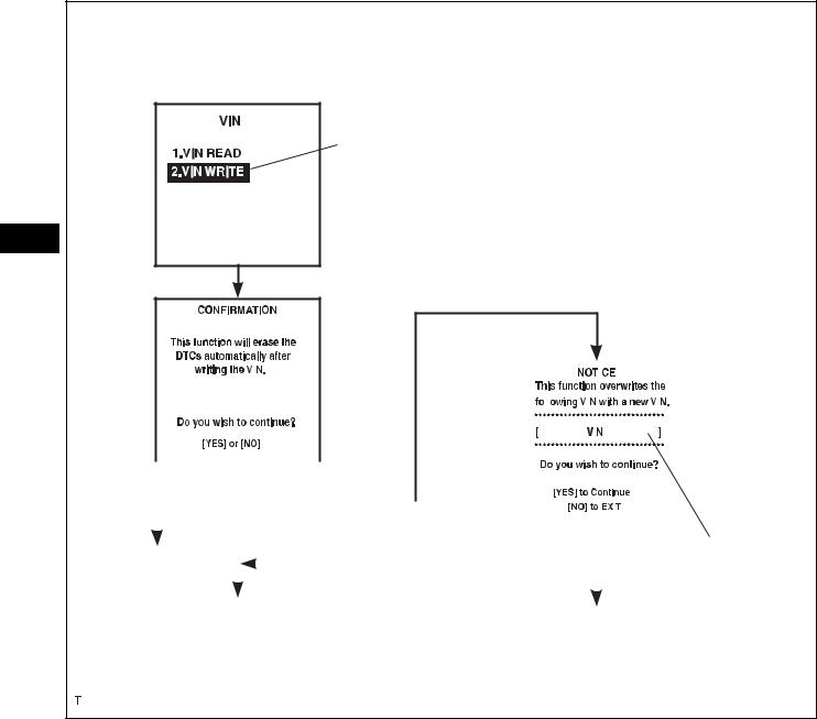
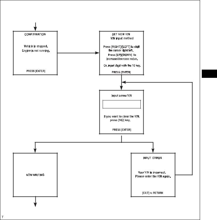
3.WRITE VIN
(a)The flowchart of the VIN writing process is shown. This process allows the VIN to be input into the ECM. If the ECM is changed, or the VINs do not match, the VIN can be registered, or overwritten in the ECM by following this procedure.
(b)Write VIN using the intelligent tester.
(c)Check the vehicle's VIN.
(d)Connect the intelligent tester to the DLC3.
(e)Turn the ignition switch on (IG).
(f)Turn the tester on.
ES–26 |
2GR-FE ENGINE CONTROL SYSTEM – SFI SYSTEM |
|
|
|
(g) Enter the following menus: DIAGNOSIS / |
|
ENHANCED OBD ll / VIN. |
Menu Screen:
Select VIN WRITE
ES
VIN Previously Stored
|
|
|
|
|
|
|
|
|
|
|
|
|
|
|
|
|
|
|
|
|
|
|
|
|
|
|
|
|
|
|
|
|
|
|
|
|
|
|
|
|
|
|
|
|
|
|
|
|
|
|
|
|
|
|
|
|
|
|
|
|
|
|
|
|
|
|
|
|
|
|
|
|
|
|
|
|
|
|
|
|
|
|
|
|
|
|
|
|
|
|
|
|
|
|
|
|
|
|
|
|
|
|
|
|
|
|
|
|
|
|
|
|
|
|
|
|
|
|
|
|
[NO] |
|
|
|
[YES] |
|
|
|
|
|
|
|
|
|
|
|
|
|
|
|
[YES] |
|
|
|
|
|
|
|
|
|||
|
|
|
|
|
|
|
|
|
|
|
|
|
||||
|
|
|
|
|
|
|
|
|
|
|
||||||
To Menu |
|
|
|
|
[YES] |
|
|
|
|
|
17-digit VIN displayed |
|||||
|
|
|
|
|
|
|
|
|
|
[NO] |
||||||
|
|
|
|
|
|
|
|
|
|
|||||||
Screen |
|
|
|
|
|
|
|
|
|
|
||||||
|
|
|
|
|
|
|
|
|
|
|
|
|
|
|||
|
|
|
Continue to next illustration |
|
|
|
|
|
|
|
|
|||||
|
|
|
To Menu Screen |
|||||||||||||
|
|
|
|
|
|
|
|
|
||||||||
A103813E01
2GR-FE ENGINE CONTROL SYSTEM – SFI SYSTEM |
ES–27 |
|
New Registration |
|
[ENTER] |
Input Instructions |
|
|
|
ES |
|
[ENTER] |
[ENTER] |
[ENTER] |
|
Input Error |
|
[EXIT] |
Continue to next illustration |
|
|
A103814E03 |

ES–28 |
2GR-FE ENGINE CONTROL SYSTEM – SFI SYSTEM |
|
Writing Successful |
Writing Error |
Communication Error |
ES |
|
|
[ENTER] |
[EXIT] |
[EXIT] |
To Menu Screen |
To Menu Screen |
To Menu Screen |
|
|
A103815E03 |

2GR-FE ENGINE CONTROL SYSTEM – SFI SYSTEM |
ES–29 |
|
CHECKING MONITOR STATUS
The purpose of the monitor result (mode 06) is to allow access to the results for on-board diagnostic monitoring tests of specific components/systems that are not continuously monitored. Examples are catalyst, evaporative emission (EVAP) and thermostat.
The monitor result allows the OBD II scan tool to display the monitor status, test value, minimum test limit and maximum test limit. These data are displayed after the vehicle has been driven to run the monitor.
When the test value is not between the minimum test limit and maximum test limit, the ECM (PCM) interprets this as a malfunction. When the component is not malfunctioning, if the difference of the test value and test limit is very small, the
component will malfunction in the near future. ES Perform the following instructions to view the monitor status. Although the Toyota diagnostic tester is used in the following instructions, it can be checked using a generic OBD II scan
tool. Refer to your scan tool operator's manual for specific procedures.
1.PERFORM MONITOR DRIVE PATTERN
The monitor results and test values can be checked with the OBD II scan tool or the intelligent tester. The engine control module (ECM) monitors the emissions-related components such as the thermostat, catalyst converter and evaporative emissions (EVAP), and determines whether they are functioning normally or not. When monitoring is finished, the ECM stores the monitor results and the test values. The monitor result indicates whether the component is functioning normally or not. The test value is the value that was used to determine the monitor result. If the test value is outside of the test limit (malfunction criterion), the ECM determines the component is malfunctioning. Some emissions-related components have multiple test values to determine monitor result. If one of these test values is outside of the test limit, the ECM determines the component is malfunctioning.
(a)Connect the intelligent tester to the DLC3.
(b)Start the engine and turn the tester on.
(c)Clear the DTCs.
(d)Run the vehicle in accordance with the applicable drive pattern described in READINESS MONITOR DRIVE PATTERN (See page ES-28). DO NOT turn the engine switch off.
NOTICE:
The test results will be lost if the engine switch is turned off.
|
|
ES–30 |
2GR-FE ENGINE CONTROL SYSTEM – SFI SYSTEM |
|
|
|
|
||
|
|
|
2. |
ACCESS MONITOR RESULT |
|
|
|
|
(a) Select the following menus on the intelligent tester: |
|
|
|
|
DIAGNOSIS, ENHANCED OBDII, MONITOR INFO |
|
|
|
|
and MONITOR RESULT. The monitor status |
|
|
|
|
appears after the component name. |
|
|
|
|
• INCMP: The component has not been monitored |
|
|
|
|
yet. |
|
|
|
|
• PASS: The component is functioning normally. |
|
|
|
|
• FAIL: The component is malfunctioning. |
|
|
|
|
(b) Confirm that the component is either PASS or FAIL. |
|
|
|
|
(c) Select the component and press ENTER. The |
|
|
|
|
accuracy test value appears if the monitor status is |
|
|
|
|
either PASS or FAIL. |
|
|
|
|
HINT: |
|
|
|
|
The monitor result might be PASS on rare |
ES |
|
|
|
|
|
|
|
occasions even if the Malfunction Indicator Lamp |
|
|
|
|
|
(MIL) is illuminated. This indicates that the system |
|
|
|
|
was malfunctioning in the previous driving cycle. |
|
|
|
|
This might be caused by an intermittent problem. |
3. CHECK COMPONENT STATUS
(a) Compare the test value with the minimum test limit (MIN LIMIT) and maximum test limit (MAX LIMIT).
(b) If the test value is between the minimum test limit and maximum test limit, the component is functioning normally. If not, the component is malfunctioning. The test value is usually significantly higher or lower than the test limit. If the test value is on the borderline of the test limit, the component will malfunction in the near future.
HINT:
The monitor result might be PASS on rare occasions even if the Malfunction Indicator Lamp (MIL) is illuminated. This indicates that the system was malfunctioning in the previous driving cycle. This might be caused by an intermittent problem.
4.MONITOR RESULT INFORMATION
If you use a generic scan tool, multiply the test value by the scaling value listed below.
A/F Sensor Bank 1:
Monitor ID |
Test ID |
Scaling |
Unit |
Description |
|
|
|
|
|
$01 |
$8E |
Multiply by 0.0003 |
No dimension |
A/F sensor deterioration level |
|
|
|
|
|
$01 |
$91 |
Multiply by 0.004 |
mA |
A/F sensor current |
|
|
|
|
|
HO2S Bank 1 Sensor 2:
Monitor ID |
Test ID |
Scaling |
Unit |
Description |
|
|
|
|
|
$02 |
$07 |
Multiply by 0.001 |
V |
Minimum sensor voltage |
|
|
|
|
|
$02 |
$08 |
Multiply by 0.001 |
V |
Maximum sensor voltage |
|
|
|
|
|
$02 |
$8F |
Multiply by 0.003 |
g |
Maximum oxygen storage capacity |
|
|
|
|
|
A/F Sensor Bank 2:
Monitor ID |
Test ID |
Scaling |
Unit |
Description |
|
|
|
|
|
$05 |
$8E |
Multiply by 0.0003 |
No dimension |
A/F sensor deterioration level |
|
|
|
|
|
$05 |
$91 |
Multiply by 0.004 |
mA |
A/F sensor current |
|
|
|
|
|
 Loading...