


2AZ-FE ENGINE MECHANICAL – ENGINE |
EM–1 |
|
ENGINE
INSPECTION
1.INSPECT ENGINE COOLANT
(a)Inspect the engine coolant (See page CO-1).
2.INSPECT ENGINE OIL
(a)Inspect the engine oil (See page LU-1).
3.INSPECT BATTERY
(a)Inspect the battery (See page CH-4).
4.INSPECT SPARK PLUGS
(a)Inspect the spark plugs (See page IG-5).
5.INSPECT AIR CLEANER FILTER ELEMENT SUBASSEMBLY
(a)Remove the air cleaner filter element sub-assembly. EM
(b)Visually check that there is no dirt, blockage, and/or damage to the air cleaner filter element.
HINT:
•If there is any dirt or a blockage in the air cleaner filter element, clean it with compressed air.
•If any dirt or a blockage remains even after cleaning the air cleaner filter element with compressed air, replace it.
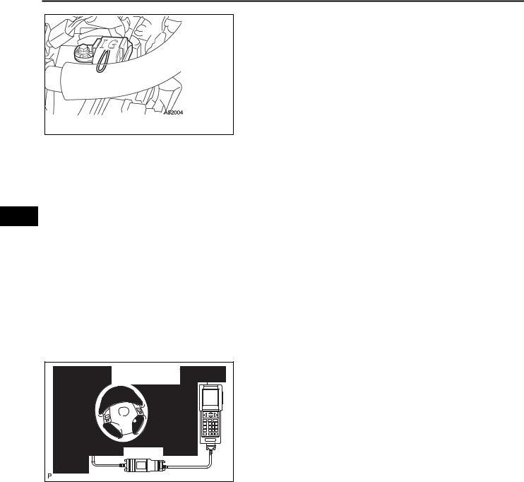
6.INSPECT IGNITION TIMING
(a)Warm up the engine.
Intelligent Tester |
(b) When using the intelligent tester: |
|
Check the ignition timing. |
||
|
||
|
(1) Connect the intelligent tester to the DLC3. |
|
|
(2) Enter DATA LIST MODE on the intelligent |
|
|
tester. |
|
|
Ignition timing: |
|
|
8 to 12° BTDC at idle |
|
CAN VIM |
HINT: |
|
Refer to the intelligent tester operator's manual |
||
DLC3 |
||
C110200E02 |
for help when selecting the DATA LIST. |
|
|
|
|
|
|
|
|
|
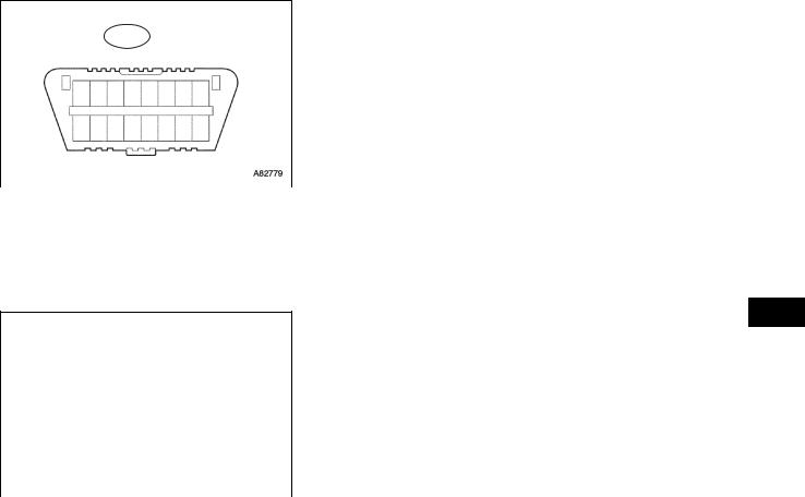
(c) When not using the intelligent tester: |
|
|
|
|
|
|
|
|
|
|
|
|
|
|
|
|
|
|
|
Check the ignition timing. |
DLC3 |
|
|
CG |
|
|
|
(1) Using SST, connect terminals 13 (TC) and 4 |
||
|
|
|
|
|
|
|
|
|
(CG) of the DLC3. |
|
|
|
|
|
|
|
|
|
SST 09843-18040 |
1 |
2 |
3 |
4 |
5 |
6 |
7 8 |
|
|
NOTICE: |
|
|
|
|
|
|
|
|
|
• Confirm the terminal numbers before |
9 10 111213141516 |
|
|
connecting them. Connection with a |
||||||
|
|
|
|
|
|
|
|
|
wrong terminal can damage the engine. |
|
|
|
|
|
TC |
|
|
• Turn off all electrical systems before |
|
|
|
|
|
|
A082779E69 |
|
|||
|
|
|
|
|
|
|
|
|
connecting the terminals. |
|
|
|
|
|
|
|
|
|
|
|
|
|
|
|
|
|
|
|
• Perform this inspection after the cooling |
|
|
|
|
|
|
|
|
|
fan motor is turned off. |
EM–2
EM
2AZ-FE ENGINE MECHANICAL – ENGINE
(2)Remove the No. 1 engine cover.
(3)Pull out the wire harness as shown in the illustration. Connect the clip of the timing light to the wire harness.
NOTICE:
•Use a timing light which can detect the first signal.
•After checking, be sure to tape the wire
harness.
A052004 (4) Check the ignition timing at idle.
Ignition timing:
8 to 12° BTDC at idle
NOTICE:
When checking the ignition timing, the transmission should be in neutral.
HINT:
After engine rpm is kept at 1,000 to 1,300 rpm for 5 seconds, check that it returns to idle speed.
(5)Disconnect terminals 13 (TC) and 4 (CG) of the DLC3.
(6)Check the ignition timing at idle.
Ignition timing:
5 to 15° BTDC at idle
(7)Confirm that the ignition timing moves to the advanced angle side when the engine rpm is increased.
(8)Remove the timing light.
Intelligent Tester |
CAN VIM |
DLC3 |
C110200E02 |
7. INSPECT ENGINE IDLE SPEED
(a) Warm up the engine.
(b) When using the intelligent tester: Check the idle speed.
(1) Connect the intelligent tester to the DLC3.
|
HINT: |
|
|
Refer to the intelligent tester operator's manual |
|
|
for further details. |
|
(2) Enter DATA LIST MODE on the intelligent |
||
|
tester. |
|
|
Idle speed |
|
|
|
|
Item |
|
Specified Condition |
|
|
|
M/T |
|
650 to 750 rpm |
|
|
|
A/T |
|
610 to 710 rpm |
|
|
|
NOTICE:
• When checking the idle speed, the transmission should be in neutral.
• Check the idle speed with the cooling fan off.
• Switch off all accessories and air conditioning before connecting the intelligent tester.
2AZ-FE ENGINE MECHANICAL – ENGINE |
EM–3 |
|
(c)When not using the intelligent tester: Check the idle speed.
|
DLC3 |
|
|
|
|
|
(1) |
Using SST, connect the tachometer tester |
||
|
|
|
|
|
|
|
|
|
probe to terminal 9 (TAC) of the DLC3. |
|
|
|
|
|
|
|
|
|
|
SST 09843-18030 |
|
1 2 3 4 5 6 |
7 8 |
|
|
|
|
(2) |
Check the idle speed. |
|||
9 10 11121314 |
15 16 |
|
|
|
|
|
|
Idle speed |
||
|
|
|
|
|
|
|
|
|||
|
|
|
|
|
Item |
|
Specified Condition |
|||
|
|
|
|
|
|
|
|
|
||
|
|
|
|
|
|
|
|
|
|
|
TAC |
|
|
|
|
|
|
M/T |
|
650 to 750 rpm |
|
|
|
A082779E70 |
|
|
||||||
|
|
|
|
|
|
|
A/T |
|
610 to 710 rpm |
|
|
|
|
|
|
|
|
|
|
||
|
|
|
|
|
|
|
||||
|
|
|
|
|
|
|
|
|
|
|
8. INSPECT COMPRESSION |
|
(a) Warm up and stop the engine. |
|
(b) Disconnect the injector connectors. |
|
(c) Remove the ignition coils. |
|
(d) Remove the spark plugs. |
EM |
(e) Check the cylinder compression pressure. |
(1)Insert a compression gauge into the spark plug hole.
(2)Fully open the throttle.
(3)While cranking the engine, measure the compression pressure.
Compression pressure:
|
|
|
1.360 MPa (13.9 kgf/ cm2, 198 psi) |
|
|
|
Minimum pressure: |
|
|
|
0.98 MPa (10 kgf/ cm2, 142 psi) |
|
A001037 |
||
|
|
|
|
|
|
|
Difference between each cylinder: |
100 kPa (1.0 kgf/ cm2, 14 psi) NOTICE:
•Always use a fully charged battery to obtain an engine speed of 250 rpm or more.
•Check the other cylinders' compression pressure in the same way.
•This measurement must be done as quickly as possible.
(4)If the cylinder compression is low, pour a small amount of engine oil into the cylinder through the spark plug hole and inspect again.
HINT:
•If adding oil increases the compression, the piston rings and/or cylinder bore may be worn or damaged.
•If pressure stays low, a valve may be stuck or seated improperly, or there may be leakage in the gasket.
9.INSPECT CO/HC
(a)Start the engine.
(b)Run the engine at 2,500 rpm for approximately 180 seconds.
(c)Insert the CO/HC meter testing probe at least 40 cm (1.3 ft) into the tailpipe during idling.

EM–4 |
2AZ-FE ENGINE MECHANICAL – ENGINE |
|
(d) Immediately check CO/HC concentration at idle and/or 2,500 rpm.
HINT:
• Complete the measuring within 3 minutes.
• Check regulations and restrictions in your area when performing 2 mode CO/HC concentration testing (engine check at both idle speed and at 2,500 rpm).
(e) If the CO/HC concentration does not comply with regulations, troubleshoot in the order given below.
(1) Check A/F sensor and heated oxygen sensor operation (See page EC-21).
(2) See the table below for possible causes, and then inspect and repair.
|
|
CO |
HC |
Problems |
|
|
Causes |
|
|
|
|
|
|
|
|
|
|
|
|
|
1. |
Faulty ignitions: |
|
EM |
|
|
|
|
|||
|
|
|
|
|
– |
Incorrect timing |
|
|
Normal |
High |
Rough idle |
|
– Fouled, shorted or improperly gapped plugs |
||
|
|
||||||
|
|
2. |
Incorrect valve clearance |
||||
|
|
|
|
|
|||
|
|
|
|
|
3. |
Leaky intake and exhaust valves |
|
|
|
|
|
|
4. |
Leaky cylinders |
|
|
|
|
|
|
|
|
|
|
|
|
|
|
1. |
Vacuum leaks: |
|
|
|
|
|
|
|
– |
PCV hoses |
|
|
Low |
High |
Rough idle |
|
– |
Intake manifold |
|
|
(fluctuating HC reading) |
|
– |
Throttle body |
||
|
|
|
|
|
|||
|
|
|
|
|
|
– |
Brake booster line |
|
|
|
|
|
2. |
Lean mixture causing misfire |
|
|
|
|
|
|
|
|
|
|
|
|
|
|
1. |
Restricted air filter |
|
|
|
|
|
|
2. |
Plugged PCV valve |
|
|
|
|
|
|
3. |
Faulty SFI system: |
|
|
|
|
|
Rough idle |
|
– |
Faulty pressure regulator |
|
|
High |
High |
|
– |
Defective ECT |
|
|
|
(black smoke from exhaust) |
|
||||
|
|
|
|
|
– |
Defective MAF meter |
|
|
|
|
|
|
|
||
|
|
|
|
|
|
– |
Faulty ECM |
|
|
|
|
|
|
– |
Faulty injectors |
|
|
|
|
|
|
– Faulty throttle position sensor |
|
|
|
|
|
|
|
|
|
2AZ-FE ENGINE MECHANICAL – DRIVE BELT |
EM–5 |
|
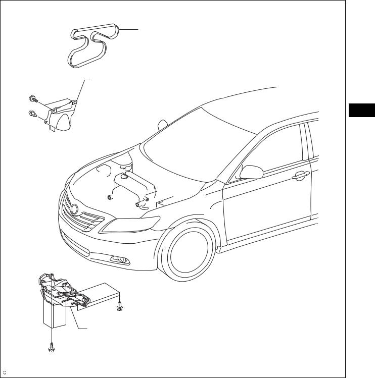
DRIVE BELT
COMPONENTS |
V-RIBBED BELT |
FRONT FENDER APRON SEAL RH |
EM |
ENGINE UNDER COVER RH |
A134946E01 |

EM–6 |
2AZ-FE ENGINE MECHANICAL – DRIVE BELT |
|
|
REMOVAL |
|
|
|
1. |
REMOVE FRONT WHEEL RH |
|
|
2. |
REMOVE ENGINE UNDER COVER RH |
|
|
3. |
REMOVE FRONT FENDER APRON SEAL RH |
|
19 mm |
4. |
REMOVE V-RIBBED BELT |
|
|
(a) Using SST and 19 mm socket wrench, loosen the V- |
||
Socket |
|
ribbed belt tensioner arm clockwise, then remove |
|
Wrench |
|
the V-ribbed belt. |
|
|
|
SST |
09216-42010 |
|
|
NOTICE: |
|
|
|
• Be sure to connect SST and the tools so that |
|
|
|
they are in line during use. |
|
SST |
|
• When retracting the tensioner, turn it |
|
A114351E03 |
|
clockwise slowly for 3 seconds or more. Do |
|
EM |
|
not apply force rapidly. |
|
|
• After the tensioner is fully retracted, do not |
||
|
|
apply force any more than necessary. |
|
INSPECTION
REPLACE
1. INSPECT V-RIBBED BELT
(a) Visually check the V-ribbed belt for excessive wear, frayed cords, etc. If any defect has been found, replace the V-ribbed belt.
HINT:
• Cracks on the rib side of a belt are considered acceptable. If the belt has chunks missing from the ribs, it should be replaced.
• A "new belt" is a belt which has been used for less than 5 minutes with the engine running.
• A "used belt" is a belt which has been used for 5 minutes or more with the engine running.
CORRECT |
INCORRECT |
|
|
|
|
A131418E01 |
|
|
|
|
19 mm |
INSTALLATION |
||
|
1. |
INSTALL V-RIBBED BELT |
||
|
Socket |
|||
|
Wrench |
|
(a) Using SST and 19 mm socket wrench, loosen the V- |
|
|
|
|
ribbed belt tensioner arm clockwise, then install the |
|
|
|
|
V-ribbed belt. |
|
|
|
|
SST |
09216-42010 |
|
|
|
NOTICE: |
|
SST |
|
|
• Be sure to connect SST and the tools so that |
|
|
A114351E03 |
|
they are in line during use. |
|
|
|
• When retracting the tensioner, turn it |
||
|
|
|
||
|
|
|
clockwise slowly for 3 seconds or more. Do |
|
|
|
|
not apply force rapidly. |
|

2AZ-FE ENGINE MECHANICAL – DRIVE BELT |
EM–7 |
|
•After the tensioner is fully retracted, do not apply force any more than necessary.
(b)After installing the V-ribbed belt, check that it fits properly in the ribbed grooves. Check to confirm that the belt has not slipped out of the grooves on the bottom of the crank pulley by hand.
2.INSTALL FRONT FENDER APRON SEAL RH
3.INSTALL ENGINE UNDER COVER RH
4.INSTALL FRONT WHEEL RH
Torque: 103 N*m (1,050 kgf*cm, 76 ft.*lbf)
EM
EM–8 |
2AZ-FE ENGINE MECHANICAL – VALVE CLEARANCE |
|
|
|
VALVE CLEARANCE |
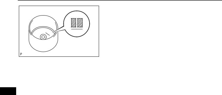
EM
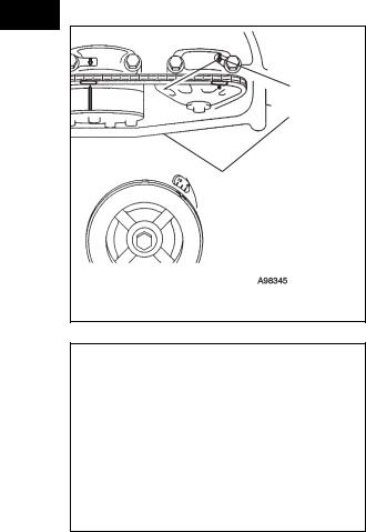
Timing Mark
Timing Mark
 Groove
A098345E09
No. 1 Cylinder TDC/Compression
IN
EX
A098170E04
ADJUSTMENT
1. |
REMOVE FRONT WHEEL RH |
||
2. |
REMOVE ENGINE UNDER COVER LH |
||
3. |
REMOVE ENGINE UNDER COVER RH |
||
4. |
REMOVE FRONT FENDER APRON SUB-ASSEMBLY |
||
|
RH |
|
|
5. |
REMOVE NO. 1 ENGINE COVER (See page EM-94) |
||
6. |
REMOVE IGNITION COIL ASSEMBLY (See page EM- |
||
|
106) |
|
|
7. |
REMOVE CYLINDER HEAD COVER SUB-ASSEMBLY |
||
|
(See page EM-21) |
||
8. |
SET NO. 1 CYLINDER TO TDC/COMPRESSION |
||
|
(a) Turn the crankshaft pulley until its groove and the |
||
|
|
timing mark "0" of the timing chain cover are |
|
|
|
aligned. |
|
|
(b) Check that each timing mark of the camshaft timing |
||
|
|
gear and sprocket is aligned with each timing mark |
|
|
|
located on the No. 1 and No. 2 bearing caps as |
|
|
|
shown in the illustration. If not, turn the crankshaft |
|
|
|
by 1 revolution (360°) to align the timing marks as |
|
|
|
above. |
|
9. |
CHECK VALVE CLEARANCE |
||
|
(a) Check only the valves indicated. |
||
|
|
(1) Using a feeler gauge, measure the clearance |
|
|
|
between the valve lifter and camshaft. |
|
|
|
Standard valve clearance (cold) |
|
|
|
|
|
Item |
|
|
Standard Condition |
|
|
|
|
Intake |
|
0.19 to 0.29 mm (0.0075 to 0.0114 in.) |
|
|
|
|
|
Exhaust |
|
0.38 to 0.48 mm (0.0150 to 0.0189 in.) |
|
|
|
|
|
(2) Record any out-of-specification valve clearance measurements. They will be used later to determine the required replacement valve clearance lifters.
(b) Turn the crankshaft 1 revolution (360°) and set the No. 4 cylinder to the TDC/compression.

2AZ-FE ENGINE MECHANICAL – VALVE CLEARANCE |
EM–9 |
|
No. 4 Cylinder TDC/Compression
IN
EX
A098171E04
A001082E01
(c) Check only the valves indicated.
|
(1) Using a feeler gauge, measure the clearance |
|
|||
|
between the valve lifter and camshaft. |
|
|||
|
Standard valve clearance (cold) |
|
|||
|
|
|
|
|
|
Item |
|
Standard Condition |
|
|
|
|
|
|
|
|
|
Intake |
|
0.19 to 0.29 mm (0.0075 to 0.0114 in.) |
|
|
|
|
|
|
|
|
|
Exhaust |
|
0.38 to 0.48 mm (0.0150 to 0.0189 in.) |
|
|
|
|
|
|
|
|
|
|
(2) Record any out-of-specification valve clearance |
|
|||
|
measurements. They will be used later to |
|
|||
|
determine the required replacement valve |
|
|||
|
lifters. |
|
|||
10. ADJUST VALVE CLEARANCE |
|
||||
(a) Remove the No. 2 camshaft (see page EM-38). |
|
||||
(b) Remove the camshaft (see page EM-38). |
|
||||
(c) Remove the valve lifters. |
|
||||
EM |
|||||
(d) |
Using a micrometer, measure the thickness of the |
||||
|
|||||
removed valve lifters.
(e)Calculate the thickness of a new lifter so that the valve clearance comes within the specified values.
New lifter thickness
Item |
Specification |
|
|
Intake |
A = B + (C - 0.24 mm (0.0095 in.)) |
Exhaust |
A = B + (C - 0.43 mm (0.0169 in.)) |
|
|
|
|
A |
New lifter thickness |
|
|
B |
Used lifter thickness |
|
|
C |
Measured valve clearance |
|
|
CALCULATION EXAMPLE (Intake):
1.Measured intake valve clearance = 0.40 mm (0.0158 in.)
(Measured - Specification = Excess clearance) (a)0.40 mm (0.0158 in.) - 0.24 mm (0.0095 in.) =
0.16 mm (0.0063 in.)
2.Measured used lifter measurement = 5.250 mm (0.2067 in.)
3.New lifter thickness = 5.410 mm (0.2130 in.) (Excess clearance + Used lifter thickness = Ideal new lifter)
(a)0.16 mm (0.0063 in.) + 5.250 mm (0.2067 in.) = 5.410 mm (0.2130 in.)
4.Closest new lifter = 5.420 mm (0.2134 in.)
– Select No. 42 lifter
EM–10 |
2AZ-FE ENGINE MECHANICAL – VALVE CLEARANCE |
|
|
(f) Select a new lifter with a thickness as close as |
|
possible to the calculated values. |
|
HINT: |
|
• Lifters are available in 35 sizes in increments of |
42 |
0.020 mm (0.0008 in.), from 5.060 to 5.740 mm |
(0.1992 to 0.2260 in.). |
|
|
• The identification number inside the valve lifters |
|
shows the value to 2 decimal places. (The |
|
illustration shows 5.420 mm (0.2134 in.) |
|
A126901E01 |
EM
2AZ-FE ENGINE MECHANICAL – VALVE CLEARANCE |
EM–11 |
|
(g) Valve lifter selection chart (intake).
|
Measured clearance |
0.0012)-(0.0000 |
0.0020)-(0.0012 |
0.0028)-(0.0020 |
0.0035)-(0.0028 |
0.0043)-(0.0036 |
0.0051)-(0.0044 |
0.0059)-(0.0052 |
0.0067)-(0.0059 |
0.0074)-(0.0067 |
0.0114)-(0.0075 |
0.0122)-(0.0115 |
0.0130)-(0.0122 |
0.0138)-(0.0130 |
0.0146)-(0.0138 |
0.0154)-(0.0146 |
0.0161)-(0.0154 |
0.0169)-(0.0162 |
0.0177)-(0.0170 |
0.0185)-(0.0178 |
0.0193)-(0.0185 |
0.0201)-(0.0193 |
0.0209)-(0.0201 |
0.0217)-(0.0209 |
0.0224)-(0.0217 |
0.0232)-(0.0225 |
0.0240)-(0.0233 |
0.0248)-(0.0241 |
0.0256)-(0.0248 |
0.0264)-(0.0256 |
0.0272)-(0.0264 |
0.0280)-(0.0272 |
0.0287)-(0.0280 |
0.0295)-(0.0288 |
0.0303)-(0.0296 |
0.0311)-(0.0304 |
0.0319)-(0.0311 |
0.0327)-(0.0319 |
0.0335)-(0.0327 |
0.0343)-(0.0335 |
0.0350)-(0.0343 |
0.0358)-(0.0351 |
0.0366)-(0.0359 |
|
|
|
|
|
|
|
|
|
|
|
|
|
|
|
|
|
|
|
|
|
|
|
|
|
|
|
|
|
|
|
|
|
|
|
|
|
|
|
|
|
|
|
|
||
|
|
mm (in.) |
|
|
|
|
|
|
|
|
|
|
|
|
|
|
|
|
|
|
|
|
|
|
|
|
|
|
|
|
|
|
|
|
|
|
|
|
|
|
|
|
|
|
|
Installed lifter |
mm (in.) |
0.030-0.000 |
0.050-0.031 |
0.070-0.051 |
0.090-0.071 |
0.110-0.091 |
0.130-0.111 |
0.150-0.131 |
0.170-0.151 |
0.189-0.171 |
0.290-0.190 |
0.310-0.291 |
0.330-0.311 |
0.350-0.331 |
0.370-0.351 |
0.390-0.371 |
0.410-0.391 |
0.430-0.411 |
0.450-0.431 |
0.470-0.451 |
0.490-0.471 |
0.510-0.491 |
0.530-0.511 |
0.550-0.531 |
0.570-0.551 |
0.590-0.571 |
0.610-0.591 |
0.630-0.611 |
0.650-0.631 |
0.670-0.651 |
0.690-0.671 |
0.710-0.691 |
0.730-0.711 |
0.750-0.731 |
0.770-0.751 |
0.790-0.771 |
0.810-0.791 |
0.830-0.811 |
0.850-0.831 |
0.870-0.851 |
0.890-0.871 |
0.910-0.891 |
0.930-0.911 |
|
thickness |
|||||||||||||||||||||||||||||||||||||||||||
|
|
|
|
|
|
|
|
|
|
|
|
|
|
|
|
|
|
|
|
|
|
|
|
|
|
|
|
|
|
|
|
|
|
|
|
|
|
|
|
|
|
|
|
|
|
5.060 |
(0.1992) |
|
|
|
|
|
|
|
|
|
|
12 14 16 18 20 22 24 26 28 30 32 34 36 38 40 42 44 46 48 50 52 54 56 58 60 62 64 66 68 70 72 74 |
|||||||||||||||||||||||||||||||
|
5.080 |
(0.2000) |
|
|
|
|
|
|
|
|
06 |
|
14 16 18 20 22 24 26 28 30 32 34 36 38 40 42 44 46 48 50 52 54 56 58 60 62 64 66 68 70 72 74 |
|
||||||||||||||||||||||||||||||
|
5.100 |
(0.2008) |
|
|
|
|
|
|
|
06 08 |
|
16 18 20 22 24 26 28 30 32 34 36 38 40 42 44 46 48 50 52 54 56 58 60 62 64 66 68 70 72 74 |
|
|
||||||||||||||||||||||||||||||
|
5.120 |
(0.2016) |
|
|
|
|
|
|
06 08 10 |
|
18 20 22 24 26 28 30 32 34 36 38 40 42 44 46 48 50 52 54 56 58 60 62 64 66 68 70 72 74 |
|
|
|
||||||||||||||||||||||||||||||
|
5.140 |
(0.2024) |
|
|
|
|
|
06 08 10 12 |
|
20 22 24 26 28 30 32 34 36 38 40 42 44 46 48 50 52 54 56 58 60 62 64 66 68 70 72 74 |
|
|
|
|
||||||||||||||||||||||||||||||
|
5.160 |
(0.2031) |
|
|
|
|
06 08 10 12 14 |
|
22 24 26 28 30 32 34 36 38 40 42 44 46 48 50 52 54 56 58 60 62 64 66 68 70 72 74 |
|
|
|
|
EM |
||||||||||||||||||||||||||||||
|
5.180 |
(0.2039) |
|
|
|
06 08 10 12 14 16 |
|
24 26 28 30 32 34 36 38 40 42 44 46 48 50 52 54 56 58 60 62 64 66 68 70 72 |
74 |
|
|
|
|
|
||||||||||||||||||||||||||||||
|
|
|
|
|
|
|
|
|
|
|
||||||||||||||||||||||||||||||||||
|
5.200 |
(0.2047) |
|
|
06 08 10 12 14 16 18 |
|
26 28 30 32 34 36 38 40 42 44 46 48 50 52 54 56 58 60 62 64 66 68 70 72 74 |
|
|
|
|
|
|
|
||||||||||||||||||||||||||||||
|
5.210 |
(0.2051) |
|
06 08 10 12 14 16 18 20 |
|
28 30 32 34 36 38 40 42 44 46 48 50 52 54 56 58 60 62 64 66 68 70 72 74 74 |
|
|
|
|
|
|
|
|||||||||||||||||||||||||||||||
|
5.220 |
(0.2055) |
|
06 08 10 12 14 16 18 20 |
|
28 30 32 34 36 38 40 42 44 46 48 50 52 54 56 58 60 62 64 66 68 70 72 74 74 |
|
|
|
|
|
|
|
|||||||||||||||||||||||||||||||
|
5.230 |
(0.2059) |
|
06 08 10 12 14 16 18 20 |
|
30 32 34 36 38 40 42 44 46 48 50 52 54 56 58 60 62 64 66 68 70 72 74 74 |
|
|
|
|
|
|
|
|
||||||||||||||||||||||||||||||
|
5.240 |
(0.2063) |
|
08 10 12 14 16 18 20 22 |
|
30 32 34 36 38 40 42 44 46 48 50 52 54 56 58 60 62 64 66 68 70 72 74 74 |
|
|
|
|
|
|
|
|
||||||||||||||||||||||||||||||
|
5.250 |
(0.2067) |
06 08 10 12 14 16 18 20 22 |
|
32 34 36 38 40 42 44 46 48 50 52 54 56 58 60 62 64 66 68 70 72 74 74 |
|
|
|
|
|
|
|
|
|
||||||||||||||||||||||||||||||
|
5.260 |
(0.2071) |
06 10 12 14 16 18 20 22 24 |
|
32 34 36 38 40 42 44 46 48 50 52 54 56 58 60 62 64 66 68 70 72 74 74 |
|
|
|
|
|
|
|
|
|
||||||||||||||||||||||||||||||
|
5.270 |
(0.2075) |
08 10 12 14 16 18 20 22 24 |
|
34 36 38 40 42 44 46 48 50 52 54 56 58 60 62 64 66 68 70 72 74 74 |
|
|
|
|
|
|
|
|
|
|
|||||||||||||||||||||||||||||
|
5.280 |
(0.2079) |
08 12 14 16 18 20 22 24 26 |
|
34 36 38 40 42 44 46 48 50 52 54 56 58 60 62 64 66 68 70 72 74 74 |
|
|
|
|
|
|
|
|
|
|
|||||||||||||||||||||||||||||
|
5.290 |
(0.2083) |
10 12 14 16 18 20 22 24 26 |
|
36 38 40 42 44 46 48 50 52 54 56 58 60 62 64 66 68 70 72 74 74 |
|
|
|
|
|
|
|
|
|
|
|
||||||||||||||||||||||||||||
|
5.300 |
(0.2087) |
10 14 16 18 20 22 24 26 28 |
|
36 38 40 42 44 46 48 50 52 54 56 58 60 62 64 66 68 70 72 74 74 |
|
|
|
|
|
|
|
|
|
|
|
||||||||||||||||||||||||||||
|
5.310 |
(0.2091) |
12 14 16 18 20 22 24 26 28 |
|
38 40 42 44 46 48 50 52 54 56 58 60 62 64 66 68 70 72 74 74 |
|
|
|
|
|
|
|
|
|
|
|
|
|||||||||||||||||||||||||||
|
5.320 |
(0.2094) |
12 16 18 20 22 24 26 28 30 |
|
38 40 42 44 46 48 50 52 54 56 58 60 62 64 66 68 70 72 74 74 |
|
|
|
|
|
|
|
|
|
|
|
|
|||||||||||||||||||||||||||
|
5.330 |
(0.2098) |
14 16 18 20 22 24 26 28 30 |
|
40 42 44 46 48 50 52 54 56 58 60 62 64 66 68 70 72 74 74 |
|
|
|
|
|
|
|
|
|
|
|
|
|
||||||||||||||||||||||||||
|
5.340 |
(0.2102) |
14 18 20 22 24 26 28 30 32 |
|
40 42 44 46 48 50 52 54 56 58 60 62 64 66 68 70 72 74 74 |
|
|
|
|
|
|
|
|
|
|
|
|
|
||||||||||||||||||||||||||
|
5.350 |
(0.2106) |
16 18 20 22 24 26 28 30 32 |
|
42 44 46 48 50 52 54 56 58 60 62 64 66 68 70 72 74 74 |
|
|
|
|
|
|
|
|
|
|
|
|
|
|
|||||||||||||||||||||||||
|
5.360 |
(0.2110) |
16 20 22 24 26 28 30 32 34 |
|
42 44 46 48 50 52 54 56 58 60 62 64 66 68 70 72 74 74 |
|
|
|
|
|
|
|
|
|
|
|
|
|
|
|||||||||||||||||||||||||
|
5.370 |
(0.2114) |
18 20 22 24 26 28 30 32 34 |
|
44 46 48 50 52 54 56 58 60 62 64 66 68 70 72 74 74 |
|
|
|
|
|
|
|
|
|
|
|
|
|
|
|
||||||||||||||||||||||||
|
5.380 |
(0.2118) |
18 22 24 26 28 30 32 34 36 |
|
44 46 48 50 52 54 56 58 60 62 64 66 68 70 72 74 74 |
|
|
|
|
|
|
|
|
|
|
|
|
|
|
|
||||||||||||||||||||||||
|
5.390 |
(0.2122) |
20 22 24 26 28 30 32 34 36 |
|
46 48 50 52 54 56 58 60 62 64 66 68 70 72 74 74 |
|
|
|
|
|
|
|
|
|
|
|
|
|
|
|
|
|||||||||||||||||||||||
|
5.400 |
(0.2126) |
20 24 26 28 30 32 34 36 38 |
|
46 48 50 52 54 56 58 60 62 64 66 68 70 72 74 74 |
|
|
|
|
|
|
|
|
|
|
|
|
|
|
|
|
|||||||||||||||||||||||
|
5.410 |
(0.2130) |
22 24 26 28 30 32 34 36 38 |
|
48 50 52 54 56 58 60 62 64 66 68 70 72 74 74 |
|
|
|
|
|
|
|
|
|
|
|
|
|
|
|
|
|
||||||||||||||||||||||
|
5.420 |
(0.2134) |
22 26 28 30 32 34 36 38 40 |
|
48 50 52 54 56 58 60 62 64 66 68 70 72 74 74 |
|
|
|
|
|
|
|
|
|
|
|
|
|
|
|
|
|
||||||||||||||||||||||
|
5.430 |
(0.2138) |
24 26 28 30 32 34 36 38 40 |
|
50 52 54 56 58 60 62 64 66 68 70 72 74 74 |
|
|
|
|
|
|
|
|
|
|
|
|
|
|
|
|
|
|
|||||||||||||||||||||
|
5.440 |
(0.2142) |
24 28 30 32 34 36 38 40 42 |
|
50 52 54 56 58 60 62 64 66 68 70 72 74 74 |
|
|
|
|
|
|
|
|
|
|
|
|
|
|
|
|
|
|
|||||||||||||||||||||
|
5.450 |
(0.2146) |
26 28 30 32 34 36 38 40 42 |
|
52 54 56 58 60 62 64 66 68 70 72 74 74 |
|
|
|
|
|
|
|
|
|
|
|
|
|
|
|
|
|
|
|
||||||||||||||||||||
|
5.460 |
(0.2150) |
26 30 32 34 36 38 40 42 44 |
|
52 54 56 58 60 62 64 66 68 70 72 74 74 |
|
|
|
|
|
|
|
|
|
|
|
|
|
|
|
|
|
|
|
||||||||||||||||||||
|
5.470 |
(0.2154) |
28 30 32 34 36 38 40 42 44 |
|
54 56 58 60 62 64 66 68 70 72 74 74 |
|
|
|
|
|
|
|
|
|
|
|
|
|
|
|
|
|
|
|
|
|||||||||||||||||||
|
5.480 |
(0.2157) |
28 32 34 36 38 40 42 44 46 |
|
54 56 58 60 62 64 66 68 70 72 74 74 |
|
|
|
|
|
|
|
|
|
|
|
|
|
|
|
|
|
|
|
|
|||||||||||||||||||
|
5.490 |
(0.2161) |
30 32 34 36 38 40 42 44 46 |
|
56 58 60 62 64 66 68 70 72 74 74 |
|
|
|
|
|
|
|
|
|
|
|
|
|
|
|
|
|
|
|
|
|
||||||||||||||||||
|
5.500 |
(0.2165) |
30 34 36 38 40 42 44 46 48 |
|
56 58 60 62 64 66 68 70 72 74 74 |
|
|
|
|
|
|
|
|
|
|
|
|
|
|
|
|
|
|
|
|
|
||||||||||||||||||
|
5.510 |
(0.2169) |
32 34 36 38 40 42 44 46 48 |
|
58 60 62 64 66 68 70 72 74 74 |
|
|
|
|
|
|
|
|
|
|
|
|
|
|
|
|
|
|
|
|
|
|
|||||||||||||||||
|
5.520 |
(0.2173) |
32 36 38 40 42 44 46 48 50 |
|
58 60 62 64 66 68 70 72 74 74 |
|
|
|
|
|
|
|
|
|
|
|
|
|
|
|
|
|
|
|
|
|
|
|||||||||||||||||
|
5.530 |
(0.2177) |
34 36 38 40 42 44 46 48 50 |
|
60 62 64 66 68 70 72 74 74 |
|
|
|
|
|
|
|
|
|
|
|
|
|
|
|
|
|
|
|
|
|
|
|
||||||||||||||||
|
5.540 |
(0.2181) |
34 38 40 42 44 46 48 50 52 |
|
60 62 64 66 68 70 72 74 74 |
|
|
|
|
|
|
|
|
|
|
|
|
|
|
|
|
|
|
|
|
|
|
|
||||||||||||||||
|
5.550 |
(0.2185) |
36 38 40 42 44 46 48 50 52 |
|
62 64 66 68 70 72 74 74 |
|
|
|
|
|
|
|
|
|
|
|
|
|
|
|
|
|
|
|
|
|
|
|
|
|||||||||||||||
|
5.560 |
(0.2189) |
36 40 42 44 46 48 50 52 54 |
|
62 64 66 68 70 72 74 74 |
|
|
|
|
|
|
|
|
|
|
|
|
|
|
|
|
|
|
|
|
|
|
|
|
|||||||||||||||
|
5.570 |
(0.2193) |
38 40 42 44 46 48 50 52 54 |
|
64 66 68 70 72 74 74 |
|
|
|
|
|
|
|
|
|
|
|
|
|
|
|
|
|
|
|
|
|
|
|
|
|
||||||||||||||
|
5.580 |
(0.2197) |
38 42 44 46 48 50 52 54 56 |
|
64 66 68 70 72 74 74 |
|
|
|
|
|
|
|
|
|
|
|
|
|
|
|
|
|
|
|
|
|
|
|
|
|
||||||||||||||
|
5.590 |
(0.2201) |
40 42 44 46 48 50 52 54 56 |
|
66 68 70 72 74 74 |
|
|
|
|
|
|
|
|
|
|
|
|
|
|
|
|
|
|
|
|
|
|
|
|
|
|
|||||||||||||
|
5.600 |
(0.2205) |
40 44 46 48 50 52 54 56 58 |
|
66 68 70 72 74 74 |
|
|
|
|
|
|
|
|
|
|
|
|
|
|
|
|
|
|
|
|
|
|
|
|
|
|
|||||||||||||
|
5.620 |
(0.2213) |
42 46 48 50 52 54 56 58 60 |
|
68 70 72 74 74 |
|
|
|
|
|
|
|
|
|
|
|
|
|
|
|
|
|
|
|
|
|
|
|
|
|
|
|
||||||||||||
|
5.640 |
(0.2220) |
44 48 50 52 54 56 58 60 62 |
|
70 72 74 74 74 |
|
|
|
|
|
|
|
|
|
|
|
|
|
|
|
|
|
|
|
|
|
|
|
|
|
|
|
||||||||||||
|
5.660 |
(0.2228) |
46 50 52 54 56 58 60 62 64 |
|
72 74 74 74 |
|
|
|
|
|
|
|
|
|
|
|
|
|
|
|
|
|
|
|
|
|
|
|
|
|
|
|
|
|||||||||||
|
5.680 |
(0.2236) |
48 52 54 56 58 60 62 64 66 |
|
74 74 74 |
|
|
|
|
|
|
|
|
|
|
|
|
|
|
|
|
|
|
|
|
|
|
|
|
|
|
|
|
|
||||||||||
|
5.700 |
(0.2244) |
50 54 56 58 60 62 64 66 68 |
|
74 74 |
|
|
|
|
|
|
|
|
|
|
|
|
|
|
|
|
|
|
|
|
|
|
|
|
|
|
|
|
|
|
|||||||||
|
5.720 |
(0.2252) |
52 56 58 60 62 64 66 68 70 |
|
74 |
|
|
|
|
|
|
|
|
|
|
|
|
|
|
|
|
|
|
|
|
|
|
|
|
|
|
|
|
|
|
|
||||||||
) |
5.740 |
(0.2260) |
54 58 60 62 64 66 68 70 72 |
|
|
|
|
|
|
|
|
|
|
|
|
|
|
|
|
|
|
|
|
|
|
|
|
|
|
|
|
|
|
|
|
A126931E02 |
||||||||
|
|
|
|
|
|
|
|
|
|
|
|
|
|
|
|
|
|
|
|
|
|
|
|
|
|
|
|
|
|
|
|
|
|
|
|
|
|
|
|
|
|
|
||
New lifter thickness
Lifter No. |
Thickness |
Lifter No. |
Thickness |
Lifter No. |
Thickness |
|
mm (in.) |
|
mm (in.) |
|
mm (in.) |
|
|
|
|
|
|
06 |
5.060 (0.1992) |
30 |
5.300 (0.2087) |
54 |
5.540 (0.2181) |
|
|
|
|
|
|

EM–12 |
2AZ-FE ENGINE MECHANICAL – VALVE CLEARANCE |
|
||||
|
|
|||||
|
|
|
|
|
|
|
Lifter No. |
Thickness |
Lifter No. |
Thickness |
Lifter No. |
Thickness |
|
|
mm (in.) |
|
mm (in.) |
|
mm (in.) |
|
|
|
|
|
|
|
|
08 |
5.080 (0.2000) |
32 |
5.320 |
(0.2094) |
56 |
5.560 (0.2189) |
|
|
|
|
|
|
|
10 |
5.100 (0.2008) |
34 |
5.340 |
(0.2102) |
58 |
5.580 (0.2197) |
|
|
|
|
|
|
|
12 |
5.120 (0.2016) |
36 |
5.360 |
(0.2110) |
60 |
5.600 (0.2205) |
|
|
|
|
|
|
|
14 |
5.140 (0.2024) |
38 |
5.380 |
(0.2118) |
62 |
5.620 (0.2213) |
|
|
|
|
|
|
|
16 |
5.160 (0.2031) |
40 |
5.400 |
(0.2126) |
64 |
5.640 (0.2220) |
|
|
|
|
|
|
|
18 |
5.180 (0.2039) |
42 |
5.420 |
(0.2134) |
66 |
5.660 (0.2228) |
|
|
|
|
|
|
|
20 |
5.200 (0.2047) |
44 |
5.440 |
(0.2142) |
68 |
5.680 (0.2236) |
|
|
|
|
|
|
|
22 |
5.220 (0.2055) |
46 |
5.460 |
(0.2150) |
70 |
5.700 (0.2244) |
|
|
|
|
|
|
|
24 |
5.240 (0.2063) |
48 |
5.480 |
(0.2157) |
72 |
5.720 (0.2252) |
|
|
|
|
|
|
|
26 |
5.260 (0.2071) |
50 |
5.500 |
(0.2165) |
74 |
5.740 (0.2260) |
|
|
|
|
|
|
|
28 |
5.280 (0.2079) |
52 |
5.520 |
(0.2173) |
- |
- |
|
|
|
|
|
|
|
EM
Standard intake valve clearance (cold): 0.19 to 0.29 mm (0.0075 to 0.0114 in.)
EXAMPLE:
The 5.250 mm (0.2067 in.) lifter is installed, and the measured clearance is 0.400 mm (0.0157 in.). Replace the 5.250 mm (0.2067 in.) lifter with a new No. 42 lifter.

2AZ-FE ENGINE MECHANICAL – VALVE CLEARANCE |
EM–13 |
|
(h) Valve lifter selection chart (exhaust).
Installed lifter |
|
-(0.00000.0012) |
-(0.00120.0020) |
-(0.00200.0028) |
-(0.00280.0035) |
-(0.00360.0043) |
-(0.00440.0051) |
-(0.00520.0059) |
-(0.00590.0067) |
-(0.00670.0075) |
-(0.00750.0083) |
-(0.00830.0091) |
-(0.00910.0098) |
-(0.00990.0106) |
-(0.01070.0114) |
-(0.01150.0118) |
-(0.01180.0157) |
-(0.01580.0165) |
-(0.01660.0173) |
-(0.01740.0181) |
-(0.01810.0189) |
-(0.01890.0197) |
-(0.01970.0205) |
-(0.02050.0213) |
-(0.02130.0220) |
-(0.02210.0228) |
-(0.02290.0236) |
-(0.02370.0244) |
-(0.02440.0252) |
-(0.02520.0260) |
-(0.02600.0268) |
-(0.02680.0276) |
-(0.02760.0283) |
-(0.02840.0291) |
-(0.02920.0299) |
-(0.03000.0307) |
-(0.03070.0315) |
-(0.03150.0323) |
-(0.03230.0331) |
-(0.03310.0339) |
-(0.03390.0346) |
-(0.03470.0354) |
-(0.03550.0362) |
-(0.03630.0370) |
-(0.03700.0378) |
-(0.03780.0386) |
-(0.03860.0394) |
-(0.03940.0402) |
-(0.04020.0409) |
-(0.04100.0417) |
-(0.04180.0425) |
Measured clearance |
|
|
|
|
|
|
|
|
|
|
|
|
|
|
|
|
|
|
|
|
|
|
|
|
|
|
|
|
|
|
|
|
|
|
|
|
|
|
|
|
|
|
|
|
|
|
|
|
|
|
|
Measured clearance |
|
|
|
|
|
|
|
|
|
|
|
|
|
|
|
|
|
|
|
|
|
|
|
|
|
|
|
|
|
|
|
|
|
|
|
|
|
|
|
|
|
|
|
|
|
|
|
|
|
|
|
|
mm (in.) |
|
|
|
|
|
|
|
|
|
|
|
|
|
|
|
|
|
|
|
|
|
|
|
|
|
|
|
|
|
|
|
|
|
|
|
|
|
|
|
|
|
|
|
|
|
|
|
|
|
|
|
mm (in.) |
|
|
|
|
|
|
|
|
|
|
|
|
|
|
|
|
|
|
|
|
|
|
|
|
|
|
|
|
|
|
|
|
|
|
|
|
|
|
|
|
|
|
|
|
|
|
|
|
|
|
thickness |
|
0.030- |
0.050- |
0.070- |
0.090- |
0.110- |
0.130- |
0.150- |
0.170- |
0.190- |
0.210- |
0.230- |
0.250- |
0.270- |
0.290- |
0.299- |
0.400- |
0.420- |
0.440- |
0.460- |
0.480- |
0.500- |
0.520- |
0.540- |
0.560- |
0.580- |
0.600- |
0.620- |
0.640- |
0.660- |
0.680- |
0.700- |
0.720- |
0.740- |
0.760- |
0.780- |
0.800- |
0.820- |
0.840- |
0.860- |
0.880- |
0.900- |
0.920- |
0.940- |
0.960- |
0.980- |
1.000- |
1.020- |
1.040- |
1.060- |
1.080- |
|
|
|
|
|
|
|
|
|
|
|
|
|
|
|
|
|
|
|
|
|
|
|
|
|
|
|
|
|
|
|
|
|
|
|
|
|
|
|
|
|
|
|
|
|
|
|
|
|
|
|
|
Installed lifter thickness |
0.000 |
0.031 |
0.051 |
0.071 |
0.091 |
0.111 |
0.131 |
0.151 |
0.171 |
0.191 |
0.211 |
0.231 |
0.251 |
0.271 |
0.291 |
0.300 |
0.401 |
0.421 |
0.441 |
0.461 |
0.481 |
0.501 |
0.521 |
0.541 |
0.561 |
0.581 |
0.601 |
0.621 |
0.641 |
0.661 |
0.681 |
0.701 |
0.721 |
0.741 |
0.761 |
0.781 |
0.801 |
0.821 |
0.841 |
0.861 |
0.881 |
0.901 |
0.921 |
0.941 |
0.961 |
0.981 |
1.001 |
1.021 |
1.041 |
1.061 |
|
mm (in.)mm (in.) |
|||||||||||||||||||||||||||||||||||||||||||||||||||
5.060 |
(0.1992) |
|
|
|
|
|
|
|
|
|
|
|
|
|
|
|
|
|
|
|
|
|
|
|
|
28 30 32 34 36 38 40 42 44 46 48 50 52 54 56 58 60 62 64 66 68 70 72 74 74 74 |
|||||||||||||||||||||||||
5.080 |
(0.2000) |
|
|
|
|
|
|
|
|
|
|
|
|
|
|
06 |
|
14 16 18 20 22 24 26 28 30 32 34 36 38 40 42 44 46 48 50 52 54 56 58 60 62 64 66 68 70 72 74 74 74 |
|
||||||||||||||||||||||||||||||||
5.100 |
(0.2008) |
|
|
|
|
|
|
|
|
|
|
|
|
|
06 08 |
|
16 18 20 22 24 26 28 30 32 34 36 38 40 42 44 46 48 50 52 54 56 58 60 62 64 66 68 70 72 74 74 74 |
|
|
||||||||||||||||||||||||||||||||
5.120 |
(0.2016) |
|
|
|
|
|
|
|
|
|
|
|
|
06 08 10 |
|
18 20 22 24 26 28 30 32 34 36 38 40 42 44 46 48 50 52 54 56 58 60 62 64 66 68 70 72 74 74 74 |
|
|
|
||||||||||||||||||||||||||||||||
5.140 |
(0.2024) |
|
|
|
|
|
|
|
|
|
|
|
06 08 10 12 |
|
20 22 24 26 28 30 32 34 36 38 40 42 44 46 48 50 52 54 56 58 60 62 64 66 68 70 72 74 74 74 |
|
|
|
|
||||||||||||||||||||||||||||||||
5.160 |
(0.2031) |
|
|
|
|
|
|
|
|
|
|
06 08 10 12 14 |
|
22 24 26 28 30 32 34 36 38 40 42 44 46 48 50 52 54 56 58 60 62 64 66 68 70 72 74 74 74 |
|
|
|
|
|
||||||||||||||||||||||||||||||||
5.180 |
(0.2039) |
|
|
|
|
|
|
|
|
|
06 08 10 12 14 16 |
|
24 26 28 30 32 34 36 38 40 42 44 46 48 50 52 54 56 58 60 62 64 66 68 70 72 74 74 74 |
|
|
|
|
|
EM |
||||||||||||||||||||||||||||||||
5.200 |
(0.2047) |
|
|
|
|
|
|
|
|
06 08 10 12 14 16 18 |
|
26 28 30 32 34 36 38 40 42 44 46 48 50 52 54 56 58 60 62 64 66 68 70 72 74 74 74 |
|
|
|
|
|
|
|||||||||||||||||||||||||||||||||
|
|
|
|
|
|
|
|
|
|
|
|
|
|
|
|
||||||||||||||||||||||||||||||||||||
5.210 |
(0.2051) |
|
|
|
|
|
|
|
06 08 10 12 14 16 18 20 |
|
26 28 30 32 34 36 38 40 42 44 46 48 50 52 54 56 58 60 62 64 66 68 70 72 74 74 74 |
|
|
|
|
|
|
|
|||||||||||||||||||||||||||||||||
5.220 |
(0.2055) |
|
|
|
|
|
|
|
06 08 10 12 14 16 18 20 |
|
28 30 32 34 36 38 40 42 44 46 48 50 52 54 56 58 60 62 64 66 68 70 72 74 74 74 |
|
|
|
|
|
|
|
|
||||||||||||||||||||||||||||||||
5.230 |
(0.2059) |
|
|
|
|
|
|
06 08 10 12 14 16 18 20 22 |
|
28 30 32 34 36 38 40 42 44 46 48 50 52 54 56 58 60 62 64 66 68 70 72 74 74 74 |
|
|
|
|
|
|
|
|
|||||||||||||||||||||||||||||||||
5.240 |
(0.2063) |
|
|
|
|
|
|
06 08 10 12 14 16 18 20 22 |
|
30 32 34 36 38 40 42 44 46 48 50 52 54 56 58 60 62 64 66 68 70 72 74 74 74 |
|
|
|
|
|
|
|
|
|
||||||||||||||||||||||||||||||||
5.250 |
(0.2067) |
|
|
|
|
|
06 08 10 12 14 16 18 20 22 24 |
|
30 32 34 36 38 40 42 44 46 48 50 52 54 56 58 60 62 64 66 68 70 72 74 74 74 |
|
|
|
|
|
|
|
|
|
|||||||||||||||||||||||||||||||||
5.260 |
(0.2071) |
|
|
|
|
|
06 08 10 12 14 16 18 20 22 24 |
|
32 34 36 38 40 42 44 46 48 50 52 54 56 58 60 62 64 66 68 70 72 74 74 74 |
|
|
|
|
|
|
|
|
|
|
||||||||||||||||||||||||||||||||
5.270 |
(0.2075) |
|
|
|
|
06 08 10 12 14 16 18 20 22 24 26 |
|
32 34 36 38 40 42 44 46 48 50 52 54 56 58 60 62 64 66 68 70 72 74 74 74 |
|
|
|
|
|
|
|
|
|
|
|||||||||||||||||||||||||||||||||
5.280 |
(0.2079) |
|
|
|
|
06 08 10 12 14 16 18 20 22 24 26 |
|
34 36 38 40 42 44 46 48 50 52 54 56 58 60 62 64 66 68 70 72 74 74 74 |
|
|
|
|
|
|
|
|
|
|
|
||||||||||||||||||||||||||||||||
5.290 |
(0.2083) |
|
|
|
06 08 10 12 14 16 18 20 22 24 26 28 |
|
34 36 38 40 42 44 46 48 50 52 54 56 58 60 62 64 66 68 70 72 74 74 74 |
|
|
|
|
|
|
|
|
|
|
|
|||||||||||||||||||||||||||||||||
5.300 |
(0.2087) |
|
|
|
06 08 10 12 14 16 18 20 22 24 26 28 |
|
36 38 40 42 44 46 48 50 52 54 56 58 60 62 64 66 68 70 72 74 74 74 |
|
|
|
|
|
|
|
|
|
|
|
|
||||||||||||||||||||||||||||||||
5.310 |
(0.2091) |
|
|
06 08 10 12 14 16 18 20 22 24 26 28 30 |
|
36 38 40 42 44 46 48 50 52 54 56 58 60 62 64 66 68 70 72 74 74 74 |
|
|
|
|
|
|
|
|
|
|
|
|
|||||||||||||||||||||||||||||||||
5.320 |
(0.2094) |
|
|
06 08 10 12 14 16 18 20 22 24 26 28 30 |
|
38 40 42 44 46 48 50 52 54 56 58 60 62 64 66 68 70 72 74 74 74 |
|
|
|
|
|
|
|
|
|
|
|
|
|
||||||||||||||||||||||||||||||||
5.330 |
(0.2098) |
|
06 08 10 12 14 16 18 20 22 24 26 28 30 32 |
|
38 40 42 44 46 48 50 52 54 56 58 60 62 64 66 68 70 72 74 74 74 |
|
|
|
|
|
|
|
|
|
|
|
|
|
|||||||||||||||||||||||||||||||||
5.340 |
(0.2102) |
|
06 08 10 12 14 16 18 20 22 24 26 28 30 32 |
|
40 42 44 46 48 50 52 54 56 58 60 62 64 66 68 70 72 74 74 74 |
|
|
|
|
|
|
|
|
|
|
|
|
|
|
||||||||||||||||||||||||||||||||
5.350 |
(0.2106) |
06 08 10 12 14 16 18 20 22 24 26 28 30 32 34 |
|
40 42 44 46 48 50 52 54 56 58 60 62 64 66 68 70 72 74 74 74 |
|
|
|
|
|
|
|
|
|
|
|
|
|
|
|||||||||||||||||||||||||||||||||
5.360 |
(0.2110) |
06 08 10 12 14 16 18 20 22 24 26 28 30 32 34 |
|
42 44 46 48 50 52 54 56 58 60 62 64 66 68 70 72 74 74 74 |
|
|
|
|
|
|
|
|
|
|
|
|
|
|
|
||||||||||||||||||||||||||||||||
5.370 |
(0.2114) |
08 10 12 14 16 18 20 22 24 26 28 30 32 34 36 |
|
42 44 46 48 50 52 54 56 58 60 62 64 66 68 70 72 74 74 74 |
|
|
|
|
|
|
|
|
|
|
|
|
|
|
|
||||||||||||||||||||||||||||||||
5.380 |
(0.2118) |
08 10 12 14 16 18 20 22 24 26 28 30 32 34 36 |
|
44 46 48 50 52 54 56 58 60 62 64 66 68 70 72 74 74 74 |
|
|
|
|
|
|
|
|
|
|
|
|
|
|
|
|
|||||||||||||||||||||||||||||||
5.390 |
(0.2122) |
10 12 14 16 18 20 22 24 26 28 30 32 34 36 38 |
|
44 46 48 50 52 54 56 58 60 62 64 66 68 70 72 74 74 74 |
|
|
|
|
|
|
|
|
|
|
|
|
|
|
|
|
|||||||||||||||||||||||||||||||
5.400 |
(0.2126) |
10 12 14 16 18 20 22 24 26 28 30 32 34 36 38 |
|
46 48 50 52 54 56 58 60 62 64 66 68 70 72 74 74 74 |
|
|
|
|
|
|
|
|
|
|
|
|
|
|
|
|
|
||||||||||||||||||||||||||||||
5.410 |
(0.2130) |
12 14 16 18 20 22 24 26 28 30 32 34 36 38 40 |
|
46 48 50 52 54 56 58 60 62 64 66 68 70 72 74 74 74 |
|
|
|
|
|
|
|
|
|
|
|
|
|
|
|
|
|
||||||||||||||||||||||||||||||
5.420 |
(0.2134) |
12 14 16 18 20 22 24 26 28 30 32 34 36 38 40 |
|
48 50 52 54 56 58 60 62 64 66 68 70 72 74 74 74 |
|
|
|
|
|
|
|
|
|
|
|
|
|
|
|
|
|
|
|||||||||||||||||||||||||||||
5.430 |
(0.2138) |
14 16 18 20 22 24 26 28 30 32 34 36 38 40 42 |
|
48 50 52 54 56 58 60 62 64 66 68 70 72 74 74 74 |
|
|
|
|
|
|
|
|
|
|
|
|
|
|
|
|
|
|
|||||||||||||||||||||||||||||
5.440 |
(0.2142) |
14 16 18 20 22 24 26 28 30 32 34 36 38 40 42 |
|
50 52 54 56 58 60 62 64 66 68 70 72 74 74 74 |
|
|
|
|
|
|
|
|
|
|
|
|
|
|
|
|
|
|
|
||||||||||||||||||||||||||||
5.450 |
(0.2146) |
16 18 20 22 24 26 28 30 32 34 36 38 40 42 44 |
|
50 52 54 56 58 60 62 64 66 68 70 72 74 74 74 |
|
|
|
|
|
|
|
|
|
|
|
|
|
|
|
|
|
|
|
||||||||||||||||||||||||||||
5.460 |
(0.2150) |
16 18 20 22 24 26 28 30 32 34 36 38 40 42 44 |
|
52 54 56 58 60 62 64 66 68 70 72 74 74 74 |
|
|
|
|
|
|
|
|
|
|
|
|
|
|
|
|
|
|
|
|
|||||||||||||||||||||||||||
5.470 |
(0.2154) |
18 20 22 24 26 28 30 32 34 36 38 40 42 44 46 |
|
52 54 56 58 60 62 64 66 68 70 72 74 74 74 |
|
|
|
|
|
|
|
|
|
|
|
|
|
|
|
|
|
|
|
|
|||||||||||||||||||||||||||
5.480 |
(0.2157) |
18 20 22 24 26 28 30 32 34 36 38 40 42 44 46 |
|
54 56 58 60 62 64 66 68 70 72 74 74 74 |
|
|
|
|
|
|
|
|
|
|
|
|
|
|
|
|
|
|
|
|
|
||||||||||||||||||||||||||
5.490 |
(0.2161) |
20 22 24 26 28 30 32 34 36 38 40 42 44 46 48 |
|
54 56 58 60 62 64 66 68 70 72 74 74 74 |
|
|
|
|
|
|
|
|
|
|
|
|
|
|
|
|
|
|
|
|
|
||||||||||||||||||||||||||
5.500 |
(0.2165) |
20 22 24 26 28 30 32 34 36 38 40 42 44 46 48 |
|
56 58 60 62 64 66 68 70 72 74 74 74 |
|
|
|
|
|
|
|
|
|
|
|
|
|
|
|
|
|
|
|
|
|
|
|||||||||||||||||||||||||
5.510 |
(0.2169) |
22 24 26 28 30 32 34 36 38 40 42 44 46 48 50 |
|
56 58 60 62 64 66 68 70 72 74 74 74 |
|
|
|
|
|
|
|
|
|
|
|
|
|
|
|
|
|
|
|
|
|
|
|||||||||||||||||||||||||
5.520 |
(0.2173) |
22 24 26 28 30 32 34 36 38 40 42 44 46 48 50 |
|
58 60 62 64 66 68 70 72 74 74 74 |
|
|
|
|
|
|
|
|
|
|
|
|
|
|
|
|
|
|
|
|
|
|
|
||||||||||||||||||||||||
5.530 |
(0.2177) |
24 26 28 30 32 34 36 38 40 42 44 46 48 50 52 |
|
58 60 62 64 66 68 70 72 74 74 74 |
|
|
|
|
|
|
|
|
|
|
|
|
|
|
|
|
|
|
|
|
|
|
|
||||||||||||||||||||||||
5.540 |
(0.2181) |
24 26 28 30 32 34 36 38 40 42 44 46 48 50 52 |
|
60 62 64 66 68 70 72 74 74 74 |
|
|
|
|
|
|
|
|
|
|
|
|
|
|
|
|
|
|
|
|
|
|
|
|
|||||||||||||||||||||||
5.550 |
(0.2185) |
26 28 30 32 34 36 38 40 42 44 46 48 50 52 54 |
|
60 62 64 66 68 70 72 74 74 74 |
|
|
|
|
|
|
|
|
|
|
|
|
|
|
|
|
|
|
|
|
|
|
|
|
|||||||||||||||||||||||
5.560 |
(0.2189) |
26 28 30 32 34 36 38 40 42 44 46 48 50 52 54 |
|
62 64 66 68 70 72 74 74 74 |
|
|
|
|
|
|
|
|
|
|
|
|
|
|
|
|
|
|
|
|
|
|
|
|
|
||||||||||||||||||||||
5.570 |
(0.2193) |
28 30 32 34 36 38 40 42 44 46 48 50 52 54 56 |
|
62 64 66 68 70 72 74 74 74 |
|
|
|
|
|
|
|
|
|
|
|
|
|
|
|
|
|
|
|
|
|
|
|
|
|
||||||||||||||||||||||
5.580 |
(0.2197) |
28 30 32 34 36 38 40 42 44 46 48 50 52 54 56 |
|
64 66 68 70 72 74 74 74 |
|
|
|
|
|
|
|
|
|
|
|
|
|
|
|
|
|
|
|
|
|
|
|
|
|
|
|||||||||||||||||||||
5.590 |
(0.2201) |
30 32 34 36 38 40 42 44 46 48 50 52 54 56 58 |
|
64 66 68 70 72 74 74 74 |
|
|
|
|
|
|
|
|
|
|
|
|
|
|
|
|
|
|
|
|
|
|
|
|
|
|
|||||||||||||||||||||
5.600 |
(0.2205) |
30 32 34 36 38 40 42 44 46 48 50 52 54 56 58 |
|
66 68 70 72 74 74 74 |
|
|
|
|
|
|
|
|
|
|
|
|
|
|
|
|
|
|
|
|
|
|
|
|
|
|
|
||||||||||||||||||||
5.620 |
(0.2213) |
32 34 36 38 40 42 44 46 48 50 52 54 56 58 60 |
|
68 70 72 74 74 74 |
|
|
|
|
|
|
|
|
|
|
|
|
|
|
|
|
|
|
|
|
|
|
|
|
|
|
|
|
|||||||||||||||||||
5.640 |
(0.2220) |
34 36 38 40 42 44 46 48 50 52 54 56 58 60 62 |
|
70 72 74 74 74 |
|
|
|
|
|
|
|
|
|
|
|
|
|
|
|
|
|
|
|
|
|
|
|
|
|
|
|
|
|
||||||||||||||||||
5.660 |
(0.2228) |
36 38 40 42 44 46 48 50 52 54 56 58 60 62 64 |
|
72 74 74 74 |
|
|
|
|
|
|
|
|
|
|
|
|
|
|
|
|
|
|
|
|
|
|
|
|
|
|
|
|
|
|
|||||||||||||||||
5.680 |
(0.2236) |
38 40 42 44 46 48 50 52 54 56 58 60 62 64 66 |
|
74 74 74 |
|
|
|
|
|
|
|
|
|
|
|
|
|
|
|
|
|
|
|
|
|
|
|
|
|
|
|
|
|
|
|
||||||||||||||||
5.700 |
(0.2244) |
40 42 44 46 48 50 52 54 56 58 60 62 64 66 68 |
|
74 74 |
|
|
|
|
|
|
|
|
|
|
|
|
|
|
|
|
|
|
|
|
|
|
|
|
|
|
|
|
|
|
|
|
|||||||||||||||
5.720 |
(0.2252) |
42 44 46 48 50 52 54 56 58 60 62 64 66 68 70 |
|
74 |
|
|
|
|
|
|
|
|
|
|
|
|
|
|
|
|
|
|
|
|
|
|
|
|
|
|
|
|
|
|
|
|
|
||||||||||||||
5.740 |
(0.2260) |
44 46 48 50 52 54 56 58 60 62 64 66 68 70 72 |
|
|
|
|
|
|
|
|
|
|
|
|
|
|
|
|
|
|
|
|
|
|
|
|
|
|
|
|
|
|
|
|
|
|
|
||||||||||||||
) |
|
|
|
|
|
|
|
|
|
|
|
|
|
|
|
|
|
|
|
|
|
|
|
|
|
|
|
|
|
|
|
|
|
|
|
|
|
|
|
|
|
|
|
|
|
|
|
|
A114356E01 |
||
New lifter thickness
Lifter No. |
Thickness |
Lifter No. |
Thickness |
Lifter No. |
Thickness |
|
mm (in.) |
|
mm (in.) |
|
mm (in.) |
|
|
|
|
|
|
06 |
5.060 (0.1992) |
30 |
5.300 (0.2087) |
54 |
5.540 (0.2181) |
|
|
|
|
|
|
EM–14 |
2AZ-FE ENGINE MECHANICAL – VALVE CLEARANCE |
|
||||
|
|
|||||
|
|
|
|
|
|
|
Lifter No. |
Thickness |
Lifter No. |
Thickness |
Lifter No. |
Thickness |
|
|
mm (in.) |
|
mm (in.) |
|
mm (in.) |
|
|
|
|
|
|
|
|
08 |
5.080 (0.2000) |
32 |
5.320 |
(0.2094) |
56 |
5.560 (0.2189) |
|
|
|
|
|
|
|
10 |
5.100 (0.2008) |
34 |
5.340 |
(0.2102) |
58 |
5.580 (0.2197) |
|
|
|
|
|
|
|
12 |
5.120 (0.2016) |
36 |
5.360 |
(0.2110) |
60 |
5.600 (0.2205) |
|
|
|
|
|
|
|
14 |
5.140 (0.2024) |
38 |
5.380 |
(0.2118) |
62 |
5.620 (0.2213) |
|
|
|
|
|
|
|
16 |
5.160 (0.2031) |
40 |
5.400 |
(0.2126) |
64 |
5.640 (0.2220) |
|
|
|
|
|
|
|
18 |
5.180 (0.2039) |
42 |
5.420 |
(0.2134) |
66 |
5.660 (0.2228) |
|
|
|
|
|
|
|
20 |
5.200 (0.2047) |
44 |
5.440 |
(0.2142) |
68 |
5.680 (0.2236) |
|
|
|
|
|
|
|
22 |
5.220 (0.2055) |
46 |
5.460 |
(0.2150) |
70 |
5.700 (0.2244) |
|
|
|
|
|
|
|
24 |
5.240 (0.2063) |
48 |
5.480 |
(0.2157) |
72 |
5.720 (0.2252) |
|
|
|
|
|
|
|
26 |
5.260 (0.2071) |
50 |
5.500 |
(0.2165) |
74 |
5.740 (0.2260) |
|
|
|
|
|
|
|
28 |
5.280 (0.2079) |
52 |
5.520 |
(0.2173) |
- |
- |
|
|
|
|
|
|
|
EM
Standard exhaust valve clearance (cold): 0.38 to 0.48 mm (0.0150 to 0.0189 in.)
EXAMPLE:
The 5.340 mm (0.2102 in.) lifter is installed, and the measured clearance is 0.430 mm (0.0169 in.). Replace the 5.340 mm (0.2102 in.) lifter with a new No. 42 lifter.
(i)Install the selected valve lifter.
11.INSTALL CAMSHAFT
(a)Apply a light coat of engine oil to the journal portion of the camshaft.
(b)Install the timing chain onto the camshaft timing
Paint Mark |
gear with the paint mark aligned with the timing |
|
mark on the camshaft timing gear as shown in the |
|
illustration. |
Timing Mark
A098176E04
(c)Examine the front marks and numbers, and check that the order is as shown in the illustration. Then install the bearing caps into the cylinder head.
(d)Apply a light coat of engine oil to the threads and under the heads of the bearing cap bolts.
A098177E03

2AZ-FE ENGINE MECHANICAL – VALVE CLEARANCE |
EM–15 |
|
No. 1
3 |
1 |
5 |
9 |
7
8
4 2 6 10
A098177E06
Paint Mark
(e)Using several steps, uniformly tighten the 10 bearing cap bolts in the sequence shown in the illustration.
Torque: No. 1 bearing cap
30 N*m (301 kgf*cm, 22 ft.*lbf) No. 3 bearing cap
9.0N*m (92 kgf*cm, 80 in.*lbf)
12.INSTALL NO. 2 CAMSHAFT
(a)Apply a light coat of engine oil to the journal portion of the No. 2 camshaft.
(b)Put the No. 2 camshaft on the cylinder head with the paint mark of the chain aligned with the timing mark on the camshaft timing sprocket.
EM
Timing Mark
A098178E03
(c)While holding the No. 2 camshaft by hand, temporarily tighten the camshaft timing sprocket set bolt.
A086659
(d)Examine the front marks and numbers, and check that the order is as shown in the illustration. Then install the bearing caps onto the cylinder head.
(e)Apply a light coat of engine oil to the threads and under the heads of the bearing cap bolts.
A098174E05
3 |
1 |
5 |
9 |
7 |
|
|
|
|
8 |
4 |
2 |
6 |
10 |
|
No. 2
A098174E07
(f)Using several steps, uniformly tighten the 10 bearing cap bolts in the sequence shown in the illustration.
Torque: No. 2 bearing cap
30 N*m (301 kgf*cm, 22 ft.*lbf) No. 3 bearing cap
9.0N*m (92 kgf*cm, 80 in.*lbf)
EM–16 |
2AZ-FE ENGINE MECHANICAL – VALVE CLEARANCE |
|
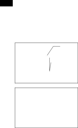
(g)While holding the camshaft with a wrench, tighten the camshaft timing sprocket set bolt.
Tighten |
Torque: 54 N*m (551 kgf*cm, 40 ft.*lbf) |
|
NOTICE: |
|
Be careful not to damage the valve lifter. |
Hold
A098173E04
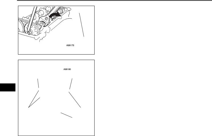
|
7 Links |
Paint Mark |
Paint Mark |
EM
Timing Mark |
Timing Mark |
||||
|
|
|
Groove |
||
|
|
|
|
|
|
|
|
|
|
|
|
|
|
|
|
A098180E04 |
|
(h)Check that the paint marks on the chain are aligned with the timing marks on the camshaft timing gear and camshaft timing sprocket. Also, check that the crankshaft pulley groove is aligned with the timing mark "0" of the timing chain cover.
13.INSTALL NO. 1 CHAIN TENSIONER (See page EM-32)
14.INSTALL CYLINDER HEAD COVER SUB-ASSEMBLY (See page EM-33)
15.INSTALL IGNITION COIL ASSEMBLY (See page EM33)
16.CHECK FOR ENGINE OIL LEAKS
17.INSTALL NO. 1 ENGINE COVER (See page EM-121)
18.INSTALL FRONT FENDER APRON RH
19.INSTALL ENGINE UNDER COVER LH
20.INSTALL ENGINE UNDER COVER RH
21.INSTALL FRONT WHEEL RH
2AZ-FE ENGINE MECHANICAL – TIMING CHAIN |
EM–17 |
|
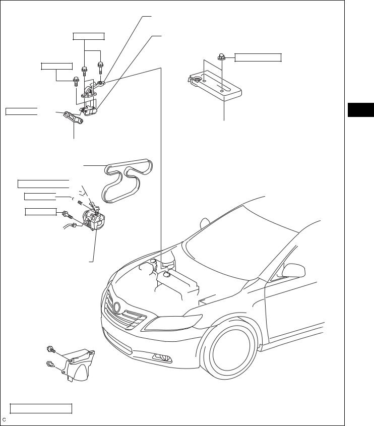
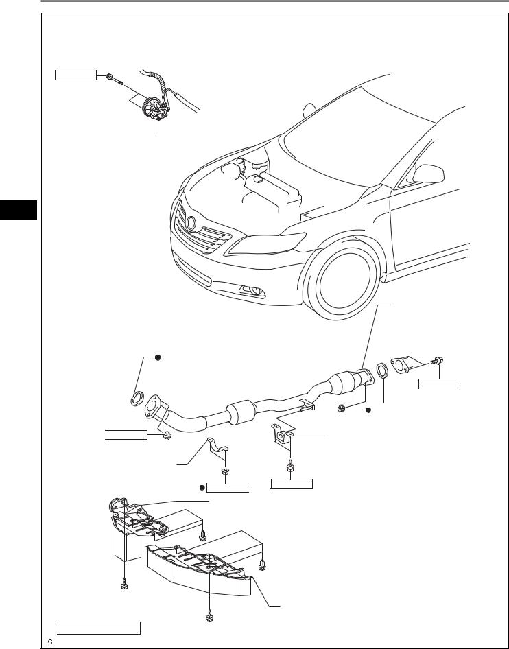
TIMING CHAIN
COMPONENTS
|
ENGINE MOVING CONTROL ROD SUB-ASSEMBLY |
64 (653, 47) |
NO. 2 ENGINE MOUNTING BRACKET RH |
|
9.0 (92, 80 in.*lbf) |
52 (531, 38)
64 (653, 47) 

NO. 1 ENGINE COVER SUB-ASSEMBLY
NO. 2 ENGINE MOUNTING STAY RH
V-RIBBED BELT
9.8 (100, 87 in.*lbf) 
 52 (531, 38)


21 (214, 15)
EM
GENERATOR ASSEMBLY
 FRONT FENDER APRON SEAL RH
N*m (kgf*cm, ft.*lbf) : Specified torque
A134948E01
EM–18 |
2AZ-FE ENGINE MECHANICAL – TIMING CHAIN |
|
43 (439, 32)
VANE PUMP ASSEMBLY
EM
|
|
|
FRONT EXHAUST |
|
|
|
PIPE ASSEMBLY |
|
EXHAUST PIPE GASKET |
|
|
|
|
|
56 (571, 41) |
|
|
|
EXHAUST PIPE GASKET |
62 (633, 46) |
|
|
REAR EXHAUST PIPE NO. 1 |
|
|
|
SUPPORT BRACKET |
FRONT EXHAUST PIPE NO. 1 |
|
|
|
SUPPORT BRACKET |
33 (337, 24) |
33 (337, 24) |
|
|
|
||
|
|
|
|
|
ENGINE UNDER COVER RH |
|
|
ENGINE UNDER COVER LH
N*m (kgf*cm, ft.*lbf) : Specified torque  Non-reusable part
A134947E01

2AZ-FE ENGINE MECHANICAL – TIMING CHAIN |
EM–19 |
|
|
|
|
|
9.0 (92, 80 in.*lbf) |
|
|
|
|
IGNITION COIL ASSEMBLY |
|
|
|
|
14 (143, 10) |
|
|
14 (143, 10) |
|
|
11 (110, 8) |
|
|
11 (110, 8) |
|
x6 |
|
x2 |
||
|
|
|
|
|
CYLINDER HEAD COVER SUB-ASSEMBLY |
|
|
EM |
|
CYLINDER HEAD COVER GASKET |
|
|
|
|
|
|
|
|
CRANK POSITION |
|
|
|
|
SENSOR |
|
|
|
9.0 (92, 80 in.*lbf) |
|
TMMK: 170 (1,733, 125) |
|
|
|
|
TMC: 180 (1,835, 133) |
|
|
|
|
CRANKSHAFT PULLEY |
|
OIL PAN SUB-ASSEMBLY |
||
|
|
|||
25 (255, 18) |
|
|
|
|
OIL PAN DRAIN PLUG |
GASKET |
|
9.0 (92, 80 in.*lbf) |
|
|
|
x2 |
x12 |
|
|
|
|
||
|
|
|
|
9.0 (92, 80 in.*lbf) |
N*m (kgf*cm, ft.*lbf) : Specified torque |
Non-reusable part |
|
|
|
|
|
|
|
A134922E01 |

EM–20 |
2AZ-FE ENGINE MECHANICAL – TIMING CHAIN |
|
|
CHAIN SUB-ASSEMBLY |
NO. 1 CHAIN VIBRATION DAMPER |
|
CRANKSHAFT TIMING SPROCKET |
CHAIN TENSIONER
SLIPPER
NO. 2 CHAIN SUB-ASSEMBLY
OIL PUMP DRIVE SPROCKET
EM |
19 (194, 14) |
|
|
SPRING |
|
|
|
|
|
NO. 1 CRANKSHAFT |
CHAIN TENSIONER |
|
|
|
|
POSITION SENSOR |
12 (122, 9.0) |
|
PLATE |
30 (301, 22) |
|
9.0 (92, 80 in.*lbf) |
|
|
OIL PUMP DRIVEN SPROCKET |
|
|
|
|
|
TIMING CHAIN GUIDE |
NO. 1 CHAIN TENSIONER |
|
|
ASSEMBLY |
9.0 (92, 80 in.*lbf)
11 (112, 8)
V-RIBBED BELT
TENSIONER
ASSEMBLY
 GASKET
55 (561, 41)
22 (220, 16) |
x4 |
STUD BOLT |
|
9.0 (92, 80 in.*lbf) |
|
60 (607, 44) |
|
TIMING CHAIN CASE OIL SEAL |
x8 |
|
|
|
25 (255, 18) |
N*m (kgf*cm, ft.*lbf) : Specified torque |
TIMING CHAIN COVER SUB-ASSEMBLY |
Non-reusable part |
|
A134923E01
2AZ-FE ENGINE MECHANICAL – TIMING CHAIN |
EM–21 |
|
REMOVAL
A112210E01 |
1.DISCONNECT CABLE FROM NEGATIVE BATTERY TERMINAL
2.REMOVE NO. 1 ENGINE COVER SUB-ASSEMBLY (See page EM-94)
3.REMOVE FRONT WHEEL RH
4.REMOVE ENGINE UNDER COVER LH
5.REMOVE ENGINE UNDER COVER RH
6.REMOVE FRONT FENDER APRON SEAL RH
7.DRAIN ENGINE OIL (See page LU-4)
8.REMOVE FRONT EXHAUST PIPE ASSEMBLY
HINT:
|
See page EX-2. |
|
|
|
EM |
||
9. |
REMOVE NO. 2 ENGINE MOUNTING STAY RH (See |
||
|
|||
|
page EM-95) |
|
|
10. |
REMOVE ENGINE MOVING CONTROL ROD SUB- |
|
|
|
ASSEMBLY (See page EM-95) |
|
|
11. |
REMOVE NO. 2 ENGINE MOUNTING BRACKET RH |
|
|
|
(See page EM-96) |
|
|
12. |
REMOVE V-RIBBED BELT (See page EM-6) |
|
|
13. |
REMOVE GENERATOR ASSEMBLY (See page CH-11) |
|
|
14. |
REMOVE VANE PUMP ASSEMBLY (See page EM- |
|
|
|
101) |
|
|
15. |
REMOVE IGNITION COIL ASSEMBLY (See page EM- |
|
|
|
106) |
|
|
16. |
DISCONNECT VENTILATION HOSE |
|
|
17. |
DISCONNECT NO. 2 VENTILATION HOSE |
|
|
18. |
REMOVE CYLINDER HEAD COVER SUB-ASSEMBLY |
|
|
|
(a) Remove the 2 bolts and disconnect the 2 engine |
|
|
|
wires. |
|
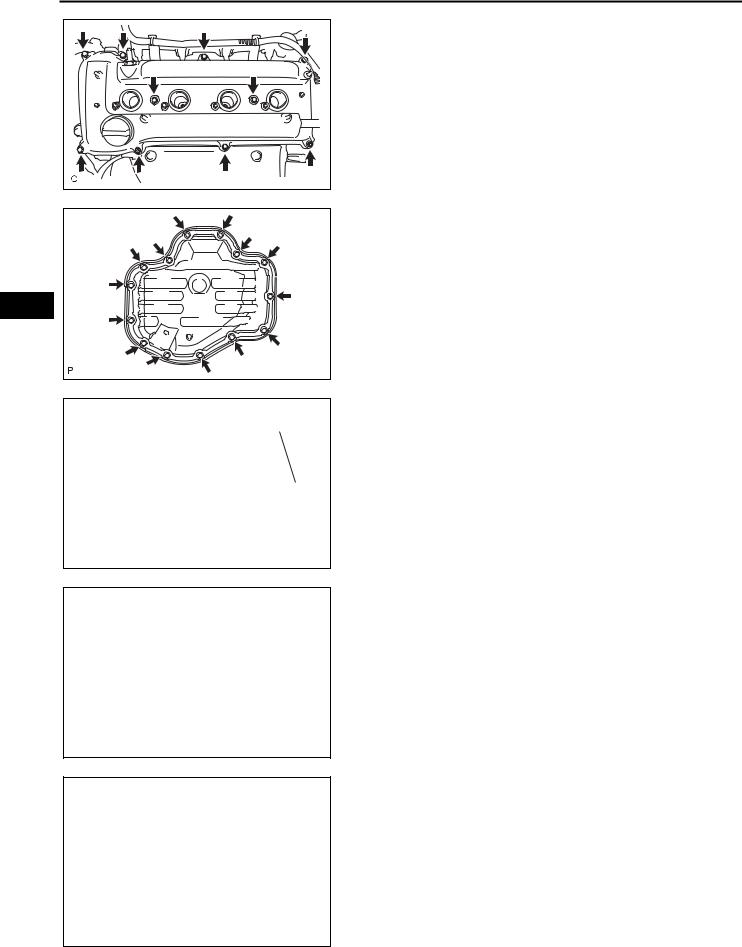
EM–22 |
2AZ-FE ENGINE MECHANICAL – TIMING CHAIN |
|
A127550E02 |
(b)Remove the 8 bolts, 2 nuts, and the cylinder head cover.
19.SET NO. 1 CYLINDER TO TDC/COMPRESSION (See page EM-8)
20.REMOVE CRANKSHAFT PULLEY (See page EM-75)
21.REMOVE CRANK POSITION SENSOR (See page ES411)
22. REMOVE OIL PAN SUB-ASSEMBLY
(a) Remove the 12 bolts and 2 nuts.
EM
A114333
 SST
SST
SST
A000019E05
(b)Insert the blade of SST between the crankcase and oil pan. Cut through the sealer and remove the oil pan.
SST 09032-00100 NOTICE:
Be careful not to damage the contact surfaces of the crankcase, chain cover and oil pan.
23.REMOVE NO. 1 CHAIN TENSIONER ASSEMBLY
(a)Remove the 2 nuts, tensioner and gasket.
NOTICE:
Do not turn the crankshaft without the chain tensioner.
A098348E01
|
|
|
|
|
|
|
|
|
|
|
|
|
|
|
|
|
|
|
|
|
|
|
|
|
|
|
|
|
|
|
|
|
|
|
|
|
|
|
|
|
|
|
|
|
|
|
|
|
|
|
|
|
|
|
|
|
|
|
|
|
|
No. 1 Engine Hanger |
|
|
No. 2 Engine Hanger |
||||
|
|
|
|
|
|
|
|
|
|
|
|
|
|
|
|
|
|
|
|
A052507E05
24. INSTALL ENGINE HANGERS
(a) Install the No. 1 engine hanger and No. 2 engine hanger with the bolts as shown in the illustration. Parts No.:
No. 1 Engine hanger |
12281-28010 |
|
|
No. 2 Engine hanger |
12282-28010 |
|
|
Bolt |
91512-61020 |
|
|
Torque: 38 N*m (387 kgf*cm, 28 ft.*lbf)
(b) Attach the sling device to the engine hangers and chain block.

2AZ-FE ENGINE MECHANICAL – TIMING CHAIN |
EM–23 |
|
25.REMOVE V-RIBBED BELT TENSIONER ASSEMBLY
(a)Lift the engine upward using the chain block.
NOTICE:
Do not lift the engine more than necessary.
A112212 |
(b) Remove the bolt, nut and V-ribbed belt tensioner.
26.REMOVE ENGINE MOUNTING INSULATOR
(a)Attach the engine chain hoist to the engine hangers. EM
CAUTION:
Do not attempt to hang the engine by hooking the chain to any other part.
(b)Remove the bolt and disconnect the engine mounting insulator FR.
A059880
M/T
A060825E02 |
A138332 |
(c)M/T:
Remove the bolt and disconnect the engine lateral control rod.
(d)Remove the 2 bolts and disconnect the steering gear return tube clamps from the frame.
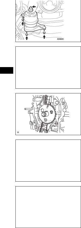
EM–24 |
2AZ-FE ENGINE MECHANICAL – TIMING CHAIN |
|||
|
|
|||
|
|
|
(e) |
Remove the 4 nuts from the engine mounting |
|
|
|
||
|
|
|
|
insulator RH. |
|
|
|
(f) |
Raise the engine and remove the engine mounting |
|
|
|
|
insulator RH. |
A059900
EM
A052481 |
A132571 |
27.REMOVE ENGINE MOUNTING BRACKET RH
(a)Remove the 3 bolts and engine mounting bracket.
28.REMOVE TIMING CHAIN COVER SUB-ASSEMBLY (See page LU-11)
29.REMOVE TIMING CHAIN CASE OIL SEAL (See page LU-12)
30.REMOVE NO. 1 CRANKSHAFT POSITION SENSOR PLATE
(a)Remove the crankshaft position sensor plate.
31.REMOVE CHAIN TENSIONER SLIPPER
(a)Remove the bolt and chain tensioner slipper.
A125372
32.REMOVE NO. 1 CHAIN VIBRATION DAMPER
(a)Remove the 2 bolts and chain vibration damper.
A125371

|
2AZ-FE ENGINE MECHANICAL – TIMING CHAIN |
EM–25 |
|
|
|
||
|
|
33. REMOVE TIMING CHAIN GUIDE |
|
|
|
|
|
|
|
(a) Remove the bolt and timing chain guide. |
|
A125373
34. REMOVE CHAIN SUB-ASSEMBLY
(a) Remove the chain sub-assembly.
EM
A128185
35.REMOVE CRANKSHAFT TIMING SPROCKET
(a)Remove the crankshaft timing sprocket.
|
|
|
|
|
A125374 |
|
|
|
|
|
|
|
|
|
36. REMOVE NO. 2 CHAIN SUB-ASSEMBLY |
|
|
|
|
|
|
|
|
|
|
|
|
|
|
|
|
|
|
|
|
|
|
|
|
|
|
90° |
|
|
|
(a) Turn the crankshaft by 90° counterclockwise to align |
|
|
|
|
|
|
|
|
the adjusting hole of the oil pump drive shaft |
|
|
|
|
|
|
|
sprocket with the groove of the oil pump. |
Groove
A098351E01
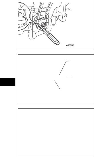
EM–26 |
2AZ-FE ENGINE MECHANICAL – TIMING CHAIN |
||
|
|
||
|
|
|
(b) Insert a 4 mm diameter bar into the adjusting hole of |
|
|
|
|
|
|
|
the oil pump drive shaft sprocket to lock the gear in |
|
|
|
position, and then remove the nut. |
Groove
A098352E01
EM
(c) Remove the bolt, chain tensioner plate and spring.
Bolt
Spring
Chain Tensioner Plate
B011415E03
(d)Remove the chain tensioner, oil pump driven sprocket and chain.
A063847

2AZ-FE ENGINE MECHANICAL – TIMING CHAIN |
EM–27 |
|
INSPECTION
1. |
INSPECT CHAIN SUB-ASSEMBLY (See page EM-138) |
|
|
2. |
INSPECT NO. 2 CHAIN SUB-ASSEMBLY (See page |
|
|
|
EM-138) |
|
|
3. |
INSPECT OIL PUMP DRIVE SPROCKET (See page |
|
|
|
EM-138) |
|
|
4. |
INSPECT OIL PUMP DRIVE SHAFT SPROCKET (See |
|
|
|
page EM-139) |
|
|
5. |
INSPECT CHAIN TENSIONER SLIPPER (See page |
|
|
|
EM-140) |
|
|
6. |
INSPECT NO. 1 CHAIN VIBRATION DAMPER (See |
|
|
|
page EM-140) |
|
|
7. |
INSPECT CHAIN TENSIONER PLATE (See page EM- |
|
|
EM |
|||
|
140) |
8.INSPECT NO. 1 CHAIN TENSIONER (See page EM140)
INSTALLATION
1.INSTALL NO. 2 CHAIN SUB-ASSEMBLY
(a)Set the crankshaft key into the left horizontal position.
(b)Turn the drive shaft so that the cutout faces upward.
B011424
Mark Link
Timing Mark
Oil Pump Drive |
Oil |
Pump |
Shaft Sprocket |
Drive Sprocket |
|
(c)Align the yellow mark links with the timing marks of each gear as shown in the illustration.
(d)Install the sprockets onto the crankshaft and oil pump shaft with the chain wrapped on the gears.
(e)Temporarily tighten the oil pump drive shaft sprocket with the nut.
Timing Mark
Mark Link
A094198E06

EM–28 |
2AZ-FE ENGINE MECHANICAL – TIMING CHAIN |
||||
|
|
||||
|
|
|
|
|
(f) Insert the damper spring into the adjusting hole, and |
|
|
|
|
|
|
|
|
|
|
|
then install the chain tensioner plate with the bolt. |
|
|
|
|
|
Torque: 12 N*m (122 kgf*cm, 9 ft.*lbf) |
|
|
|
|
|
|
|
|
|
Bolt |
|
|
|
|
|
|
|
|
Spring
Chain Tensioner Plate
A090851E03
EM
Groove
A052512E02
(g)Align the adjusting hole of the oil pump drive shaft sprocket with the groove of the oil pump.
(h)Insert a 4 mm diameter bar into the adjusting hole of the oil pump drive shaft gear to lock the gear in position, and then tighten the nut.
Torque: 30 N*m (301 kgf*cm, 22 ft.*lbf)
(i)Rotate the crankshaft clockwise by 90°, and align the crankshaft key to the top.
A036525
2.INSTALL CRANKSHAFT TIMING SPROCKET
(a)Install the crankshaft timing sprocket.
A125374

2AZ-FE ENGINE MECHANICAL – TIMING CHAIN |
EM–29 |
|
A132570 |
3.INSTALL NO. 1 CHAIN VIBRATION DAMPER
(a)Install the chain vibration damper with the 2 bolts.
Torque: 9.0 N*m (92 kgf*cm, 80 in.*lbf)
|
|
4. INSTALL CHAIN SUB-ASSEMBLY |
|
|
|
|
|
||
|
|
(a) Set the No. 1 cylinder to TDC/compression. |
|
|
|
|
(1) Turn the camshafts with a wrench (using the |
|
|
|
|
hexagonal lobe) to align the timing marks of the |
|
|
|
|
camshaft timing gear with each timing mark |
|
|
Timing Marks |
|
located on the No. 1 and No. 2 bearing caps as |
|
|
EM |
||||
|
|
shown in the illustration. |
||
|
|
Timing Marks
A053018E05
A052505
Timing Mark
(2)Using the crankshaft pulley bolt, turn the crankshaft to position with the key on the crankshaft upward.
(b)Install the chain onto the crankshaft timing sprocket with the gold or pink mark link aligned with the timing mark on the crankshaft.
Mark Link
A094576E01
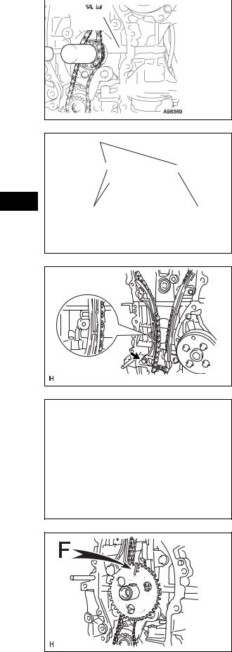
EM–30 |
2AZ-FE ENGINE MECHANICAL – TIMING CHAIN |
||
|
|
||
|
|
|
(c) Using SST and a hammer, tap in the crankshaft |
|
|
|
|
|
SST |
|
timing sprocket. |
|
|
|
SST 09309-37010 |
A098369E01
(d) Align the gold or yellow link with each timing mark Mark Link located on the camshaft timing gear and sprocket,
then install the chain.
EM
Timing Mark |
Timing Mark |
|
A098370E01 |
|
5. INSTALL CHAIN TENSIONER SLIPPER |
Hold |
(a) Install the chain tensioner slipper with the bolt. |
|
Torque: 19 N*m (194 kgf*cm, 14 ft.*lbf) |
|
A124787E01 |
A125373 |
A124770 |
6.INSTALL TIMING CHAIN GUIDE
(a)Install the timing chain guide with the bolt.
Torque: 9.0 N*m (92 kgf*cm, 80 in.*lbf)
7.INSTALL NO. 1 CRANKSHAFT POSITION SENSOR PLATE
(a)Install the sensor plate with the "F" mark facing forward.
8.INSTALL TIMING CHAIN CASE OIL SEAL (See page LU-15)
9.INSTALL TIMING CHAIN COVER SUB-ASSEMBLY (See page LU-15)
 Loading...