


2AZ-FE EMISSION CONTROL – EMISSION CONTROL SYSTEM |
EC–1 |
|
EMISSION CONTROL SYSTEM
PARTS LOCATION
VENTILATION VALVE |
VACUUM SWITCHING VALVE |
EC |
CANISTER |
HEATED OXYGEN SENSOR |
FUEL TANK CAP |
AIR FUEL RATIO SENSOR |
A135646E03 |

EC–2 |
2AZ-FE EMISSION CONTROL – EMISSION CONTROL SYSTEM |
|
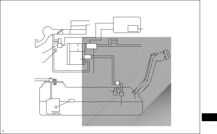
SYSTEM DIAGRAM
For PZEV : |
|
|
|
Air Cleaner |
ECM |
|
|
|
Intake Manifold |
|
Soak Timer |
|
Canister |
Air Filter |
|
|
|
EVAP VSV |
|
|
Service Port |
|
Fuel Cap |
|
|
|
|
Pump Module |
|
|
Roll-over Valve |
|
EC |
Cut-off Valve |
|
|
|
|
|
Fuel Tank |
|
|
|
A128935E01 |
2AZ-FE EMISSION CONTROL – EMISSION CONTROL SYSTEM |
EC–3 |
|
Except PZEV : |
|
|
Air Cleaner |
ECM |
|
|
|
|
Intake Manifold |
|
Soak Timer |
Canister |
Air Filter |
|
|
|
|
EVAP VSV |
|
|
Service Port |
|
Fuel Cap |
|
|
|
Pump Module |
|
|
Roll-over Valve |
|
|
Cut-off Valve |
|
|
Fuel Tank |
|
EC |
|
|
A128936E01 |
EC–4 |
2AZ-FE EMISSION CONTROL – EMISSION CONTROL SYSTEM |
|
|
N17 |
|
|
|
|
|
|
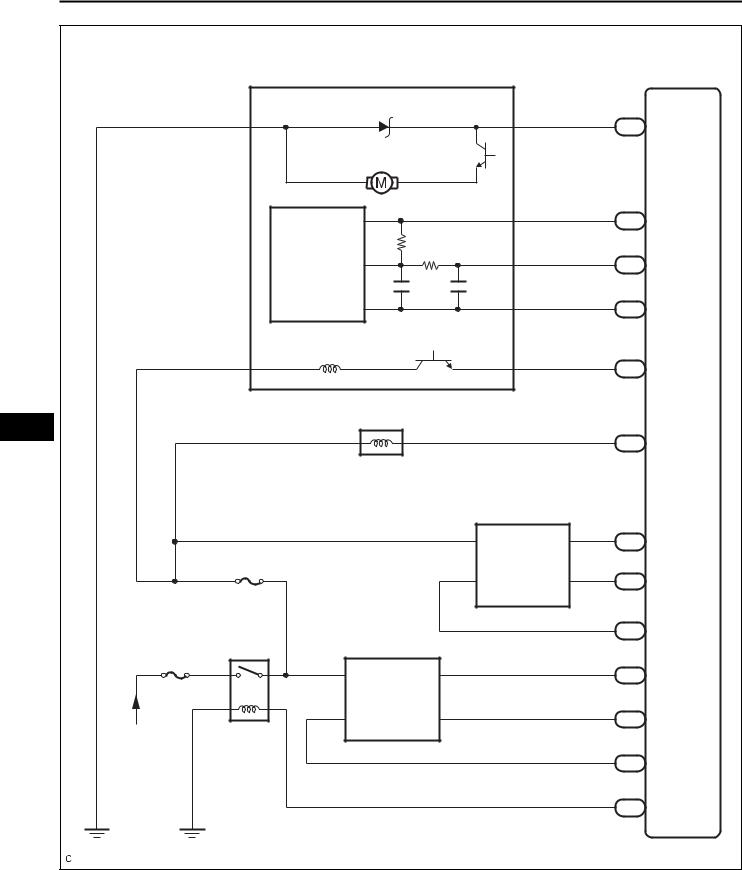
Canister Pump Module |
|
|
|
ECM |
|
|
MGND |
|
MTRB |
|
34 |
|
|
|
|
A24 |
|
||
|
6 |
|
|
1 |
|
|
|
|
|
|
|
||
|
Leak Detection Pump |
|
|
|
|
|
|
|
|
VCC |
|
70 |
|
|
Canister |
|
4 |
C24 |
VCPP |
|
|
|
|
||||
|
|
|
|
|
||
|
Pressure |
|
VOUT |
|
71 |
|
|
Sensor |
|
3 |
C24 PPMP |
||
|
|
|
|
|||
|
|
|
|
94 |
|
|
|
|
|
SGND |
|
|
|
|
|
|
|
C24 EPPM |
||
|
|
|
|
2 |
||
|
|
|
|
|
|
|
|
Vent Valve |
VGND |
|
42 |
|
|
|
VLVB |
|
|
A24 |
VPMP |
|
|
9 |
|
|
8 |
||
|
|
|
|
|
||
EC |
C6 VSV (Purge) |
|
|
|
|
|
|
|
|
|
49 |
|
|
1 |
2 |
|
|
C24 PRG |
||
|
C22 |
|
||||
|
|
|
|
|||
|
|
|
Heated Oxgen Sensor |
|
|
|
|
|
|
|
|
87 |
|
|
|
|
+B |
E2 |
C24 |
EX1B |
|
EFI No. 3 |
|
2 |
4 |
64 |
|
|
|
|
|
|
||
|
C15 |
|
HT1B |
OX1B |
C24 |
OX1B |
|
Air Fuel Ratio Sensor |
1 |
3 |
|
|
|
|
|
|
|
|
47 |
|
|
EFI |
|
|
|
C24 HT1B |
|
EFI-MAIN |
|
|
|
113 |
|
|
|
|
|
|
|
||
|
+B |
A1A- |
4 |
|
C24 |
A1A- |
|
2 |
|
|
112 |
|
|
|
|
|
|
|
|
|
|
HA1A |
A1A+ |
3 |
|
C24 |
A1A+ |
From Battery |
1 |
|
|
109 |
|
|
|
|
|
|
|
||
|
|
|
|
|
|
|
|
|
|
|
|
C24 HA1A |
|
|
|
|
|
|
44 |
|
|
|
|
|
|
A24 MREL |
|
|
|
|
|
|
|
A135723E01 |
2AZ-FE EMISSION CONTROL – EMISSION CONTROL SYSTEM |
EC–5 |
|
B000412
A128092 |
ON-VEHICLE INSPECTION
1.VISUALLY INSPECT HOSE, CONNECTIONS AND GASKETS
(a)Check that there are no cracks, leaks or damage. HINT:
•Detachment or other problems with the engine oil dipstick, filler cap, PCV hose and other components may cause the engine to run improperly.
•Disconnection, looseness or cracks in the parts of the air induction system between the throttle body and cylinder head will allow air suction and
cause an engine failure or engine malfunctions. If the result is not as specified, replace the parts as necessary.
2.INSPECT FUEL CUT RPM
(a)Start and warm up the engine.
(b)Open the throttle valve and keep the engine speed at 3,000 rpm.
(c)Use a sound scope to check for injector operating sounds.
(d)Check that when the accelerator pedal is released,
injector operating sounds stop momentarily (at |
EC |
|||
2,500 rpm) and then resume (at 1400 rpm). |
||||
|
||||
Standard |
|
|
|
|
Item |
Specified condition |
|
|
|
|
|
|
|
|
Fuel cut off rpm |
2,500 rpm |
|
|
|
|
|
|
|
|
Fuel return rpm |
1,400 rpm |
|
|
|
|
|
|
|
|
If the result is not specified, check the injectors, wiring and ECM.
3.INSPECT LINE AND CONNECTORS
(a)Visually check for loose connections, sharp bends or damage.
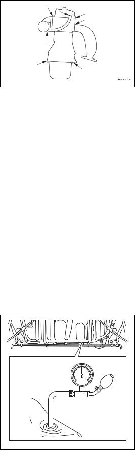
4.CHECK AIR TIGHTNESS IN FUEL TANK AND FILLER PIPE
(a)Disconnect the vent line hose from the fuel tank.
(b)Connect the pressure gauge to the fuel tank.
(c)Apply pressure to the fuel tank to create an internal pressure of 4 kPa (41 gf/cm2, 0.58 psi).
(d)Check that the internal pressure of the fuel tank is maintained for 1 minute.
(e)Check the connected portions of each hose and pipe.
(f)Check the installed parts on the fuel tank.
If any malfunctions, damage or other problems are found, replace the fuel tank and filler pipe.
(g)Reconnect the vent line hose to the fuel tank.

EC–6 |
2AZ-FE EMISSION CONTROL – EMISSION CONTROL SYSTEM |
|
|
5. REMOVE FUEL TANK ASSEMBLY |
|
|
(a) |
Disconnect the vent line hose from the fuel tank. |
|
(b) |
Connect the pressure gauge to the fuel tank. |
|
(c) |
Fill the fuel tank with fuel. |
|
(d) |
Apply pressure of 4 kPa (41 gf/cm2, 0.58 psi) to the |
|
|
vent port of the fuel tank. |
|
|
HINT: |
|
|
Check the amount of fuel in the fuel tank. When the |
|
|
fuel tank is full, the float valve of the fill check valve |
|
|
is closed and no air can pass through. |
|
(e) |
Remove the fuel tank cap, and check that the |
|
|
pressure drops. |
|
|
If the pressure does not drop, replace the fuel tank |
|
|
assembly. |
Fuel Tank Cap |
(f) |
Reconnect the vent line hose to the fuel tank. |
|
A126204E01 |
|
EC
|
6. REMOVE AIR INLET LINE |
|
Air Inlet Hose |
(a) |
Disconnect the air inlet line hose from the charcoal |
Air |
|
canister. |
|
(b) |
Check that air can flow freely into the air inlet line. |
|
|
If air cannot flow freely into the air inlet line, repair or |
|
|
replace it. |
|
(c) |
Reconnect the air inlet line hose to the charcoal |
|
|
canister. |
A128093E02

2AZ-FE EMISSION CONTROL – CANISTER |
EC–7 |
|
|
CANISTER |
|
COMPONENTS |
|
for PZEV: |
|
|
EC |
CHARCOAL CANISTER ASSEMBLY |
|
39 (398, 29) |
|
N*m (kgf*cm, ft.*lbf) : Specified torque |
|
|
A135649E03 |

EC–8 |
2AZ-FE EMISSION CONTROL – CANISTER |
|
except PZEV: |
EC |
CHARCOAL CANISTER ASSEMBLY |
39 (398, 29) |
N*m (kgf*cm, ft.*lbf) : Specified torque |
A135648E06 |
 Loading...