


WIPER AND WASHER – WIPER AND WASHER SYSTEM |
WW–1 |
||||
|
|||||
|
WIPER AND WASHER SYSTEM |
||||
|
PRECAUTION |
|
|||
1. |
EXPRESSIONS OF IGNITION SWITCH |
||||
|
|
(a) The type of ignition switch used on this model differs |
|||
|
|
|
according to the specifications of the vehicle. |
||
|
|
|
The expressions listed in the table below are used |
||
|
|
|
in this section. |
|
|
|
|
|
|
|
|
Switch Type |
|
Ignition Switch (position) |
|
Engine Switch (condition) |
|
|
|
|
|
|
|
|
Ignition switch off |
|
LOCK |
|
Off |
|
|
|
|
|
|
Expression |
Ignition switch on (IG) |
|
ON |
|
On (IG) |
|
|
|
|
|
|
Ignition switch on (ACC) |
|
ACC |
|
On (ACC) |
|
|
|
|
|||
|
|
|
|
|
|
|
Engine start |
|
START |
|
Start |
|
|
|
|
|
|
2. |
PRECAUTION OF WASHER NOZZLE ADJUSTMENT |
||||
|
|
(a) Do not clean or adjust the washer nozzle with a |
|||
|
|
|
safety pin, etc. because; |
|
|
(1) the washer nozzle tip is made of resin and could be damaged.
(2) adjustment is not necessary because the washer nozzle is a spray type. If it is necessary to change the nozzle angle, replace the washer nozzle with one that has a different nozzle angle. (See page WW-28)
(b) In case the washer nozzle is clogged with wax, etc., remove it and clean the nozzle hole with a soft resin brush, etc.
WW

WW–2 |
WIPER AND WASHER – WIPER AND WASHER SYSTEM |
|
PARTS LOCATION
WASHER NOZZLE
FRONT WIPER ARM AND
BLADE ASSEMBLY RH
WINDSHIELD WASHER JAR
AND PUMP ASSEMBLY
- FRONT WASHER MOTOR |
ENGINE ROOM J/B AND R/B |
|
- ALT FUSE |
WIPER SWITCH |
|
WW
MAIN BODY ECU (INSTRUMENT PANEL J/B)
-IG1 RELAY
-WIP FUSE
-WASH FUSE
FRONT WIPER ARM AND BLADE ASSEMBLY LH
WINDSHIELD WIPER MOTOR AND LINK ASSEMBLY
-FRONT WIPER MOTOR
-WINDSHIELD WIPER LINK ASSEMBLY
E119081E01

WIPER AND WASHER – WIPER AND WASHER SYSTEM |
WW–3 |
|
SYSTEM DIAGRAM
Wiper Control Switch |
|
|
|
|
|||
+B |
+2 |
+1 |
+S |
INT1 |
INT2 |
B1 |
|
MIST |
|
|
|
|
|
Washer Switch |
|
OFF |
|
|
|
|
|
||
|
|
|
|
|
|
|
|
INT |
|
|
|
|
|
W |
EW |
LO |
|
|
|
|
|
OFF |
|
HI |
|
|
|
|
|
ON |
|
Front Wiper |
|
|
|
|
|
|
|
Relay Circuit |
|
|
|
|
|
|
|
|
|
|
|
|
|
Tr2 |
|
|
|
|
|
|
|
Tr1 |
|
|
|
|
|
C1 |
|
C2 |
|
|
|
|
|
|
|
Washer Motor |
|
|
|
|
|
|
|
|
WW |
|
+2 |
+1 |
+S |
+B |
|
|
|
|
|
LO |
|
Front Wiper Motor |
|
||
|
HI |
|
|
|
|
|
|
|
|
|
|
|
|
|
B126225E02 |

WW–4
WW
WIPER AND WASHER – WIPER AND WASHER SYSTEM
SYSTEM DESCRIPTION
1.WASHER LINKED OPERATION
(a)This system operates the front wipers at a low speed immediately after a jet of washer fluid when the front washer switch is turned on for approximately 0.3 seconds or more. If the switch is turned off within approximately 1.5 seconds, the system stops the wipers when the switch is turned off. If the switch is turned on for approximately 1.5 seconds or more, the system stops the wipers approximately 2.2 seconds after the switch is turned off.
2.INTERMITTENT OPERATION
(a)The system operates the front wipers once in approximately 1.6 to 10.7 seconds when the front wiper switch is turned to the INT position. The intermittent time can be adjusted between 1.6 and 10.7 seconds.
(b)If the wiper control switch is turned to the INT position, current flows from the already charged capacitor C1 to Tr1 (transistor) through terminals INT1 and INT2 of the wiper control switch. When Tr1 turns on, current flows from terminal +S of the wiper control switch to terminal +1 of the wiper control switch, to terminal +1 of the wiper motor, to the wiper motor and finally to the ground, causing the wiper motor to operate. At the same time, current flows from capacitor C1 to terminal INT1 of the wiper control switch and then INT2. When the current flow from capacitor C1 ends, Tr1 turns off to stop the relay contact point and halt the wiper motor. When the relay contact point turns off, capacitor C1 begins to charge again and Tr1 remains off until charging has been completed. This period corresponds to the intermittent time. When capacitor C1 is fully charged, Tr1 turns on and then the relay contact point activates, causing the motor to operate. This cycle is the intermittent operation. The intermittent time can be adjusted by using the intermittent time adjust dial (variable resistor) to change the charge time of capacitor C1.

WIPER AND WASHER – WIPER AND WASHER SYSTEM |
WW–5 |
|
Wiper Control Switch |
|
|
|
|
|||
+B |
+2 |
+1 |
+S |
INT1 |
INT2 |
B1 |
|
MIST |
|
|
|
|
|
Washer Switch |
|
OFF |
|
|
|
|
|
||
|
|
|
|
|
|
|
|
INT |
|
|
|
|
|
W |
EW |
LO |
|
|
|
|
|
OFF |
|
HI |
|
|
|
|
|
ON |
|
Front Wiper |
|
|
|
|
|
|
|
Relay Circuit |
|
|
|
|
|
|
|
|
|
|
|
|
|
Tr2 |
|
|
|
|
|
|
|
Tr1 |
|
|
|
|
|
C1 |
|
C2 |
|
|
|
|
|
|
|
Washer Motor |
|
|
+2 |
+1 |
+S |
+B |
|
|
WW |
|
|
LO |
|
|
Front Wiper Motor |
||
|
|
|
|
|
|||
|
HI |
|
|
|
|
|
|
|
|
|
|
|
|
|
B126226E02 |
WW–8 |
WIPER AND WASHER – FRONT WIPER MOTOR |
|
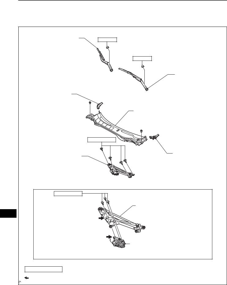
FRONT WIPER MOTOR
COMPONENTS |
|
|
FRONT WIPER ARM AND |
20 (204, 15) |
|
BLADE ASSEMBLY RH |
||
|
20 (204, 15) |
|
|
FRONT WIPER ARM AND |
|
|
BLADE ASSEMBLY LH |
|
FRONT FENDER TO |
|
|
COWL SIDE SEAL RH |
|
|
|
COWL TOP VENTILATOR LOUVER |
|
|
SUB-ASSEMBLY |
|
|
7.5 (77, 66 in.*lbf) |
|
WINDSHIELD WIPER MOTOR |
FRONT FENDER TO |
|
COWL SIDE SEAL LH |
||
AND LINK ASSEMBLY |
||
|
||
5.4 (55, 48 in.*lbf) |
|
|
WW |
WINDSHIELD WIPER LINK ASSEMBLY |
|
|
||
|
WINDSHIELD WIPER MOTOR ASSEMBLY |
|
N*m (kgf*cm, ft.*lbf) : Specified torque |
||
Apply MP grease |
|
|
|
E128804E01 |
|

WIPER AND WASHER – FRONT WIPER MOTOR |
WW–9 |
|
E128807 |
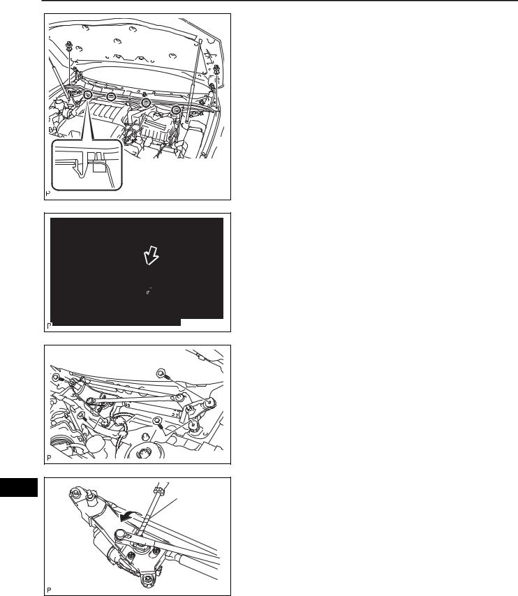
REMOVAL
1.REMOVE FRONT WIPER ARM AND BLADE ASSEMBLY LH
(a)Remove the nut and the front wiper arm and blade assembly LH.
E128808 |
E128809 |
E128810 |
2.REMOVE FRONT WIPER ARM AND BLADE ASSEMBLY RH
(a)Remove the nut and the front wiper arm and blade assembly RH.
3.REMOVE FRONT FENDER TO COWL SIDE SEAL LH
(a)Disengage the claw and remove the front fender to cowl side seal LH.
4.REMOVE FRONT FENDER TO COWL SIDE SEAL RH
(a)Disengage the claw and remove the front fender to cowl side seal RH.
WW
WW–10 |
WIPER AND WASHER – FRONT WIPER MOTOR |
|
E128811 |
E128812 |
E128813 |
5.REMOVE COWL TOP VENTILATOR LOUVER SUBASSEMBLY
(a)Remove the 2 clips.
(b)Disengage the 4 claws and remove the cowl top ventilator louver sub-assembly.
6.REMOVE WINDSHIELD WIPER MOTOR AND LINK ASSEMBLY
(a)Disconnect the connector.
(b)Remove the 4 bolts and the windshield wiper motor and link assembly.
WW |
Protective |
|
Tape |
|
E128814E01 |
7.REMOVE WINDSHIELD WIPER MOTOR ASSEMBLY
(a)Using a screwdriver, separate the No. 2 windshield wiper link rod from the crank arm pivot of the front wiper motor assembly as shown in the illustration. HINT:
Tape the screwdriver tip before use.

WIPER AND WASHER – FRONT WIPER MOTOR |
WW–11 |
|
E128815 |
(b)Move the crank arm in the direction indicated by the arrow.
E128816 |
(c)Remove the 3 bolts and the windshield wiper motor assembly from the windshield wiper link assembly.
Connector Front View: |
INSPECTION |
|
|||
|
B |
1. |
INSPECT WINDSHIELD WIPER MOTOR ASSEMBLY |
|
|
|
B1 |
|
(for TMC Made) |
|
|
|
|
|
|
||
|
+2 |
+S |
(a) |
LO Operation Check |
|
|
|
(1) Connect a positive (+) battery lead to terminal |
|
||
|
|
|
|
|
|
|
|
|
|
B1-5 (+1) of the connector, and a negative (-) |
|
|
+1 |
E |
|
battery lead to terminal B1-4 (E), and check |
|
|
|
|
|
that the motor operates at low speed (LO). |
|
|
|
E034081E37 |
(b) |
HI Operation Check |
|
|
|
|
(1) Connect a positive (+) lead to terminal B1-3 |
|
|
|
|
|
|
|
|
|
|
|
|
(+2) of the connector, and a negative (-) battery |
|
|
|
|
|
lead to terminal B1-4 (E), and check that the |
|
|
|
|
|
motor operates at high speed (HI). |
|
|
|
|
(c) Automatic Stop Operation Check |
|
|
|
|
|
|
(1) Put matchmarks on the windshield wiper motor |
|
|
|
|
|
assembly. The matchmarks will be used to |
|
|
|
|
|
confirm the return of the motor shaft to the park |
WW |
22° |
+5° |
|
|
position. |
|
|
-10° |
|
|
|
|
|
Automatic Stop Position |
|
|
|
|
|
|
B131458E01 |
|
|
|
 Loading...