


2AZ-FE ENGINE CONTROL SYSTEM – SFI SYSTEM |
ES–1 |
|
SFI SYSTEM
PRECAUTION
NOTICE:
•Perform RESET MEMORY (AT initialization) when replacing the automatic transmission assembly, engine assembly or ECM (See page AX-16).
•Perform REGISTRATION (VIN registration) when
replacing the ECM (See page ES-16).
HINT:
Initialization cannot be completed by removing the battery.
ES
|
|
ES–2 |
2AZ-FE ENGINE CONTROL SYSTEM – SFI SYSTEM |
|
|
|
|
||
|
|
|
|
DEFINITION OF TERMS |
|
|
|
|
|
|
|
Terms |
|
Definition |
|
|
|
|
|
|
|
Monitor Description |
|
Description of what ECM monitors and how detects malfunctions (monitoring purpose and |
|
|
|
details). |
|
|
|
|
|
|
|
|
|
|
|
|
|
Related DTCs |
|
Group of diagnostic trouble codes that are output by ECM based on the same malfunction |
|
|
|
detection logic. |
|
|
|
|
|
|
|
|
|
|
|
|
|
|
|
Preconditions that allow ECM to detect malfunctions. |
|
|
Typical Enabling Condition |
|
With all preconditions satisfied, ECM sets DTC when monitored value(s) exceeds |
|
|
|
|
malfunction threshold(s). |
|
|
|
|
|
|
|
|
|
Order of monitor priority, applied if multiple sensors and components involved in single |
|
|
Sequence of Operation |
|
malfunction detection process. |
|
|
|
Each sensor and component monitored in turn, when previous detection operation is |
|
|
|
|
|
|
|
|
|
|
completed. |
ES |
|
|
|
|
|
Required Sensor/Components |
|
Sensors and components used by ECM to detect each malfunction. |
|
|
|
|
Number of times ECM checks for each malfunction during each driving cycle. |
|
|
|
|
|
|
|
|
|
|
"Once per driving cycle" means ECM only performs checks for that malfunction once in |
|
|
Frequency of Operation |
|
single driving cycle. |
|
|
|
|
"Continuous" means ECM performs checks for that malfunction whenever enabling |
|
|
|
|
conditions are met. |
|
|
|
|
|
|
|
Duration |
|
Minimum time for which ECM must detect continuous deviation in monitored value(s) in |
|
|
|
order to set DTC. Timing begins when Typical Enabling Conditions are met. |
|
|
|
|
|
|
|
|
|
|
|
|
|
Malfunction Thresholds |
|
Value, beyond which, ECM determines malfunctions exist and sets DTCs. |
|
|
|
|
|
|
|
|
|
Timing of MIL illumination after malfunction is detected. |
|
|
MIL Operation |
|
"Immediate" means ECM illuminates MIL as soon as malfunction is detected. |
|
|
|
"2 driving cycle" means ECM illuminates MIL if the same malfunction is detected second |
|
|
|
|
|
|
|
|
|
|
time in the next sequential driving cycle. |
|
|
|
|
|
2AZ-FE ENGINE CONTROL SYSTEM – SFI SYSTEM |
ES–3 |
|
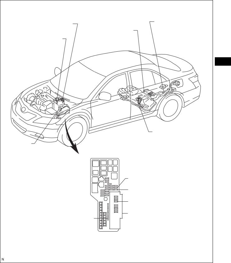
PARTS LOCATION
PZEV:
PURGE VSV
MASS AIR FLOW METER
ECM
ENGINE ROOM R/B AND
ENGINE ROOM J/B
EFI MAIN FUSE
CANISTER PUMP MODULE
CANISTER
ES
FUEL PUMP
EFI NO. 3 FUSE
EFI NO. 2 FUSE
EFI NO. 1 FUSE
INTEGRATION RELAY (ENGINE ROOM J/B)
-EFI RELAY
-CIRCUIT OPENING RELAY
A137360E01

ES–4 |
2AZ-FE ENGINE CONTROL SYSTEM – SFI SYSTEM |
|
EXCEPT PZEV: |
CANISTER |
PURGE VSV |
CANISTER PUMP MODULE |
MASS AIR FLOW METER |
ES |
FUEL PUMP |
ECM |
ENGINE ROOM R/B AND |
ENGINE ROOM J/B |
EFI NO. 3 FUSE |
EFI NO. 2 FUSE |
EFI NO. 1 FUSE |
INTEGRATION RELAY |
EFI MAIN FUSE |
(ENGINE ROOM J/B) |
- EFI RELAY |
- CIRCUIT OPENING RELAY |
A137361E01 |

2AZ-FE ENGINE CONTROL SYSTEM – SFI SYSTEM |
ES–5 |
|
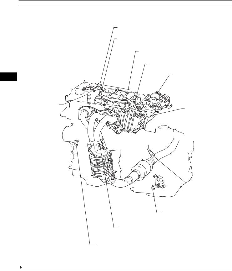
PZEV: |
|
CAMSHAFT TIMING OIL CONTROL VALVE ASSEMBLY |
|
FUEL INJECTOR |
|
KNOCK SENSOR |
|
CAMSHAFT POSITION SENSOR |
|
THROTTLE BODY |
ES |
IGNITION COIL |
|
INTAKE MANIFOLD |
|
RUNNER VALVE (IMRV) |
|
ENGINE COOLANT |
|
TEMPERATURE |
|
SENSOR |
|
HEATED OXYGEN |
|
SENSOR |
|
PARK/NEUTRAL POSITION SW |
|
AIR-FUEL RATIO SENSOR |
|
CRANKSHAFT POSITION SENSOR |
|
A135059E01 |
|
ES–6 |
2AZ-FE ENGINE CONTROL SYSTEM – SFI SYSTEM |
|
|
EXCEPT PZEV: |
|
CAMSHAFT TIMING OIL CONTROL VALVE ASSEMBLY |
|
FUEL INJECTOR |
|
KNOCK SENSOR |
|
CAMSHAFT POSITION SENSOR |
ES |
THROTTLE BODY |
|
|
|
IGNITION COIL |
|
ENGINE COOLANT |
|
TEMPERATURE |
|
SENSOR |
|
HEATED OXYGEN |
|
SENSOR |
|
PARK/NEUTRAL POSITION SW |
|
AIR-FUEL RATIO SENSOR |
|
CRANKSHAFT POSITION SENSOR |
|
A132270E01 |

2AZ-FE ENGINE CONTROL SYSTEM – SFI SYSTEM |
ES–7 |
|
INSTRUMENT PANEL J/B |
|
|
- IGN FUSE |
|
|
- STOP FUSE |
CLUTCH START SWITCH |
|
|
|
|
|
COMBINATION METER |
|
|
IGNITION SWITCH |
ES |
|
|
|
DLC3 |
STOP LIGHT SW |
|
|
ACCELERATOR PEDAL ROD |
|
|
|
A132271E01 |
ES–8 |
2AZ-FE ENGINE CONTROL SYSTEM – SFI SYSTEM |
|
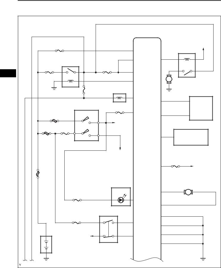
SYSTEM DIAGRAM
|
|
|
ECM |
|
|
|
EFI No. 1 |
|
|
|
To IGN |
|
|
|
|
C/OPN |
|
|
|
|
BATT |
|
|
|
|
|
|
|
|
|
EFI |
|
+B |
FC |
|
EFI MAIN |
|
EFI No. 2 |
|
|
|
ES |
|
|
|
|
|
|
|
+B2 |
|
|
|
|
|
|
|
M Fuel Pump |
|
|
|
|
MREL |
|
|
|
|
|
Purge VSV |
|
|
|
|
EFI No. 3 |
|
|
|
|
|
|
PRG |
TC |
|
|
IG SW |
IGN |
|
||
|
|
DLC3 |
|||
|
|
|
|
||
|
|
|
IGSW |
|
|
ST/AM2 |
|
TACH |
|
||
|
To |
|
|||
|
|
|
|
|
|
ALT |
AM2 |
IG2 |
C/OPN |
|
|
AM1 |
|
|
|
||
|
|
|
|
||
|
AM1 |
IG1 |
|
ALT |
Generator |
|
|
|
|||
|
To Park/Neutral Position SW |
|
|
||
|
|
|
|
|
ETCS |
|
|
|
|
+BM |
To Battery |
FL |
|
|
Combination |
|
IMRV (Intake Manifold |
MAIN |
|
|
|
||
|
|
Meter |
|
||
|
|
|
|
Runner Valve) Motor |
|
|
|
|
|
|
|
|
GAUGE No. 2 |
MIL |
IAC+*1 |
M |
|
|
|
||||
|
|
|
W |
IAC-*1 |
|
|
|
Stop Light SW |
|
||
|
|
|
|
||
|
STOP |
|
|
E1 |
|
|
|
|
STP |
E01 |
|
|
|
|
|
|
|
|
To IGN |
ST1- |
E03 |
|
|
|
|
|
|||
|
Battery |
|
|
E04 |
|
|
|
*1: PZEV Only |
|
|
|
|
|
|
|
|
A132314E01 |

2AZ-FE ENGINE CONTROL SYSTEM – SFI SYSTEM |
ES–9 |
|
ECM |
|
|
|
|
|
Throttle Actuator |
|
Mass Air Flow Meter |
M+ |
|
|
|
|
|
|
|
M- |
|
|
E2G |
|
|
|
VG |
GE01 |
|
|
THA |
|
No. 4 Fuel Injector |
ES |
ETHA |
#40 |
|
|
|
|
|
|
|
|
No. 3 Fuel Injector |
|
Engine Coolant Temperature Sensor |
#30 |
To |
|
INJ |
|
||
|
|
||
|
|
|
|
THW |
|
No. 2 Fuel Injector |
|
|
|
|
|
ETHW |
#20 |
|
|
|
|
No. 1 Fuel Injector |
|
Air-fuel Ratio Sensor |
#10 |
|
|
|
|
|
|
HA1A |
|
Knock Sensor |
|
A1A+ |
|
|
|
|
|
|
|
|
KNK1 |
|
|
A1A- |
EKNK |
|
|
|
|
|
|
Heated Oxygen Sensor |
|
|
|
HT1B |
E02 |
|
|
|
|
|
|
OX1B |
|
|
|
|
ME01 |
|
|
EX1B |
|
|
|
|
|
A132315E01 |
|

ES–10 |
2AZ-FE ENGINE CONTROL SYSTEM – SFI SYSTEM |
|
|
ECM |
|
|
|
Crankshaft Position Sensor |
|
|
Camshaft Timing Oil Control Valve |
|
|
|
|
||
|
NE+ |
OC1+ |
|
|
|
|
|
|
|
|
NE- |
OC1- |
|
|
|
|
|
|
|
ES |
|
|
|
To INJ |
|
|
|
|
|
Camshaft Position Sensor |
|
IGT1 |
No. 1 Ignition Coil |
|
|
|
|||
|
G2- |
|
|
|
|
G2+ |
IGT2 |
No. 2 Ignition Coil |
|
|
|
|
|
|
|
|
IGT3 |
No. 3 Ignition Coil |
|
Throttle Position |
VCTA |
IGT4 |
No. 4 Ignition Coil |
|
Sensor |
|
|||
|
VTA1 |
IGF1 |
|
|
|
VTA2 |
|
|
|
|
ETA |
|
Park/Neutral |
To IG SW |
|
|
Position SW or |
ST |
|
|
|
|
Clutch Start SW |
|
IMRV Position |
NSW*2 |
|
|
|
VCIA*1 |
|
|
|
|
Sensor |
|
|
|
|
|
|
|
|
|
|
IACA*1 |
|
To IG SW |
|
|
EIA*1 |
STA |
|
|
|
|
|
To Starter |
|
|
|
|
|
|
*1: PZEV Only |
|
|
|
|
*2: Automatic Transaxle Only |
|
|
|
|
|
|
|
|
A132316E01 |
2AZ-FE ENGINE CONTROL SYSTEM – SFI SYSTEM |
ES–11 |
|
|
ECM |
|
|
|
|
|
|
FAN No. 3 |
|
|
|
Combination Meter |
FANL |
|
|
To IG1 |
|
SPD |
A/C Condenser |
|
|
|
|
|
|
To Battery |
|
||
|
|
|
|
||
|
|
Fan Motor |
|
|
|
|
|
|
|
|
|
|
|
M |
|
|
|
Transponder Key ECU |
IMO |
|
|
|
|
|
|
|
|
|
|
|
IMI |
|
|
|
ES |
|
|
FAN No. 2 |
Radiator Fan Motor |
||
Accelerator Pedal Position Sensor |
|
|
|
M |
|
|
|
|
|
|
|
|
VCP2 |
FAN No. 1 |
|
|
|
|
|
|
|
|
|
IC |
VPA2 |
|
|
|
|
|
EPA2 |
|
|
To Battery |
|
|
|
|
|
|
|
|
FANH |
|
|
|
|
|
VCPA |
|
|
|
|
IC |
VPA |
Canister Pump Module |
|
|
|
|
|
|
|
||
|
EPA |
|
Vent Valve |
|
|
|
|
|
|
|
|
|
VPMP |
|
|
|
|
|
VCPP |
Canister Pressure |
To EFI No. 3 |
|
|
|
PPMP |
Sensor |
|
|
|
CANH |
|
|
|
|
|
CANH |
|
|
|
|
|
|
EPPM |
|
|
|
|
CANL |
CANL |
|
|
|
|
|
MPMP |
|
|
|
|
PS Oil Pressure SW |
|
|
M |
|
|
|
|
Leak Detection Pump |
|
|
|
|
PSW |
|
|
|
|
|
EC |
|
|
|
|
|
EOM |
|
|
|
|
|
|
|
|
A132317E01 |
|

ES–12 |
2AZ-FE ENGINE CONTROL SYSTEM – SFI SYSTEM |
|
|
|
|
|
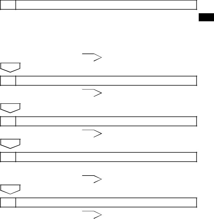
HOW TO PROCEED WITH |
|
|
|
|
|
TROUBLESHOOTING |
|
|
|
|
|
HINT: |
|
|
|
|
|
*: Use the intelligent tester. |
|
|
|
|
|||
|
|
1 |
VEHICLE BROUGHT TO WORKSHOP |
||
|
|
|
|
|
|
|
|
|
|
|
|
|
|
NEXT |
|
|
|
|
|
|
|||
|
|
2 |
CUSTOMER PROBLEM ANALYSIS |
||
ES |
|||||
|
|
|
|
||
|
|
|
|
||
|
|
|
|
|
|
|
|
NEXT |
|
|
|
|
|
|
|||
|
|
3 |
CONNECT INTELLIGENT TESTER TO DLC3* |
||
|
|
|
|
|
|
|
|
|
|
HINT: |
|
|
|
|
|
If the display indicates a communication fault in the tester, |
|
|
|
|
|
inspect the DLC3. |
|
|
|
|
|
|
|
|
|
NEXT |
|
|
|
|
|
|
|||
|
|
4 |
CHECK FOR DTC AND FREEZE FRAME DATA* |
||
|
|
|
|
|
|
|
|
|
|
HINT: |
|
|
|
|
|
Record or print DTCs and freeze frame data, if necessary. |
|
|
|
|
|
|
|
|
|
NEXT |
|
|
|
|
|
|
|||
|
|
5 |
CLEAR DTC AND FREEZE FRAME DATA* |
||
|
|
|
|
|
|
|
|
|
|
|
|
|
|
NEXT |
|
|
|
|
|
|
|||
|
|
6 |
CONDUCT VISUAL INSPECTION |
||
|
|
|
|
|
|
|
|
|
|
|
|
|
|
NEXT |
|
|
|
|
|
|
|||
|
|
7 |
SET CHECK MODE DIAGNOSIS* |
||
|
|
|
|
|
|
NEXT

2AZ-FE ENGINE CONTROL SYSTEM – SFI SYSTEM |
ES–13 |
|
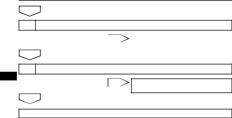
8 CONFIRM PROBLEM SYMPTOMS
HINT:
If the engine does not start, first perform the "CHECK DTC" procedures and "CONDUCT BASIC INSPECTION" procedures below.
Result
Result |
Proceed to |
|
|
Malfunction does not occur |
A |
|
|
Malfunction occurs |
B |
|
|
B GO TO STEP 10
A
9 SIMULATE SYMPTOMS
NEXT
10 CHECK FOR DTC*
Result
ES
Result |
Proceed to |
|
|
Trouble code |
A |
|
|
No code |
B |
|
|
B GO TO STEP 12
A
11 REFER TO DTC CHART
NEXT
GO TO STEP 14
12 CONDUCT BASIC INSPECTION
Result
Result |
Proceed to |
|
|
Malfunctioning parts not confirmed |
A |
|
|
Malfunctioning parts confirmed |
B |
|
|
B GO TO STEP 17

ES–14 |
2AZ-FE ENGINE CONTROL SYSTEM – SFI SYSTEM |
|
|||
|
|
|
|||
|
|
|
|
|
|
A |
|
|
|
|
|
|
|
|
|
|
|
13 |
REFER TO PROBLEM SYMPTOMS TABLE |
|
|||
|
|
|
|
|
|
|
|
|
Result |
|
|
|
|
|
|
|
|
|
|
|
Result |
|
Proceed to |
|
|
|
|
|
|
|
|
|
Malfunctioning circuit confirmed |
|
A |
|
|
|
|
|
|
|
|
|
Malfunctioning parts confirmed |
|
B |
|
|
|
|
|
|
B GO TO STEP 17
ES A
14 |
CHECK ECM POWER SOURCE CIRCUIT |
|
||
|
|
|
|
|
|
|
|
|
|
NEXT |
|
|
|
|
|
|
|
|
|
15 |
CONDUCT CIRCUIT INSPECTION |
|
||
|
|
|
|
|
|
|
|
Result |
|
|
|
|
|
|
|
|
|
Result |
Proceed to |
|
|
|
|
|
|
|
|
Malfunction not confirmed |
A |
|
|
|
|
|
|
|
|
Malfunction confirmed |
B |
B GO TO STEP 18
A
16 CHECK FOR INTERMITTENT PROBLEMS
NEXT
GO TO STEP 18
17CONDUCT PARTS INSPECTION
NEXT
18IDENTIFY PROBLEM
NEXT
2AZ-FE ENGINE CONTROL SYSTEM – SFI SYSTEM |
ES–15 |
|
19ADJUST AND/OR REPAIR
NEXT
20CONDUCT CONFIRMATION TEST
NEXT
END |
|
ES |
|
|
|
|
|
|
|
|
|

ES–16
ES
2AZ-FE ENGINE CONTROL SYSTEM – SFI SYSTEM
CHECK FOR INTERMITTENT PROBLEMS
HINT:
Inspect the vehicle's ECM using check mode. Intermittent problems are easier to detect with the intelligent tester when the ECM is in check mode. In check mode, the ECM uses 1 trip detection logic, which is more sensitive to malfunctions than normal mode (default), which uses 2 trip detection logic.
1.Clear the DTCs (See page ES-38).
2.Switch the ECM from normal mode to check mode using the intelligent tester (See page ES-41).
3.Perform a simulation test.
4.Check and wiggle the harness(es), connector(s) and terminal(s).
2AZ-FE ENGINE CONTROL SYSTEM – SFI SYSTEM |
ES–17 |
|
BASIC INSPECTION
When a malfunction is not confirmed by the DTC check, troubleshooting should be carried out in all circuits considered to be possible causes of the problem. In many cases, by carrying out the basic engine check shown in the following flowchart, the location of the problem can be found quickly and efficiently. Therefore, using this check is essential when engine troubleshooting.
1 CHECK BATTERY VOLTAGE
NOTICE:
Conduct this check with the engine stopped and ignition ES switch off.
Result
|
|
|
Result |
Proceed to |
|
|
|
|
|
|
|
11 V or more |
OK |
|
|
|
|
|
|
|
|
Below 11 V |
NG |
|
|
|
|
|
|
|
NG |
|
|
|
|
|
CHARGE OR REPLACE BATTERY |
||
|
|
|
|
|
OK
2 CHECK WHETHER ENGINE WILL CRANK
NG |
|
PROCEED TO PROBLEM SYMPTOMS |
|
|
TABLE |
|
||
|
|
|
OK
3 CHECK WHETHER ENGINE STARTS
NG |
|
GO TO STEP 6 |
|
|
|
OK
4 CHECK AIR FILTER
(a)Visually check that the air filter is not excessively contaminated with dirt or oil.
NG |
|
REPLACE AIR FILTER |
|
|
|
OK
5 CHECK IDLING SPEED
NG |
|
TROUBLESHOOT IDLING SPEED AND |
|
|
PROCEED TO NEXT STEP |
|
||
|
|
|
ES–18 |
2AZ-FE ENGINE CONTROL SYSTEM – SFI SYSTEM |
|
OK
6 CHECK FUEL PRESSURE
NG |
|
TROUBLESHOOT FUEL PRESSURE AND |
|
|
PROCEED TO NEXT STEP |
|
||
|
|
|
OK
7 CHECK FOR SPARKS
ES
NG |
TROUBLESHOOT SPARK AND PROCEED |
|
TO NEXT STEP |
|
OK
PROCEED TO PROBLEM SYMPTOMS TABLE
2AZ-FE ENGINE CONTROL SYSTEM – SFI SYSTEM |
ES–19 |
|
REGISTRATION
NOTICE:
The Vehicle Identification Number (VIN) must be input into the replacement ECM.
HINT:
The VIN is a 17-digit alphanumeric number. The intelligent tester is required to register the VIN.
1. DESCRIPTION |
|
|
This registration section consists of 3 parts: Input |
|
|
Instructions, Read VIN and Write VIN. |
|
|
(a) Input Instructions: Explains the general VIN input |
|
|
instructions when using the intelligent tester. |
|
|
ES |
||
(b) Read VIN: Explains the VIN reading process in a |
||
flowchart. This process allows the VIN stored in the |
|
|
ECM to be read in order to confirm that the two |
|
|
VINs, provided with the vehicle and stored in the |
|
|
vehicle's ECM, are the same. |
|
(c)Write VIN: Explains the VIN writing process in a flowchart. This process allows the VIN to be input into the ECM. If the ECM is changed, or the vehicle VIN and ECM VIN do not match, the VIN can be registered or overwritten in the ECM by following this procedure.
2.INPUT INSTRUCTIONS
(a)Intelligent tester
The arrow buttons (UP, DOWN, RIGHT and LEFT) and numerical buttons (0 to 9) are used to input the VIN.
(b)Cursor Operation
To move the cursor around the tester screen, press the RIGHT and LEFT buttons.
(c)Alphabetical Character Input
(1)Press the UP and DOWN buttons to select the desired alphabetical character.
(2)After selection, the cursor should move.
(d)Numeric Character Input
(1)Press the numerical button corresponding to the number that you want to input.
(2)After input, the cursor should move. HINT:
Numerical characters can also be selected by using the UP and DOWN buttons.
(e)Correction
(1)When correcting the input character(s), put the cursor onto the character using the RIGHT and LEFT buttons.
(2)Select or input the correct character using the UP/DOWN buttons, or the numerical buttons.
(f)Finishing Input Operation
(1)Make sure that the input VIN matches the vehicle VIN after input.
(2)Press the ENTER button on the tester.

ES–20 |
2AZ-FE ENGINE CONTROL SYSTEM – SFI SYSTEM |
|
3.READ VIN
(a)Confirm the vehicle VIN.
(b)Connect the intelligent tester to the DLC3.
(c)Turn the ignition switch to the ON position.
(d)Turn the tester on.
(e)Select the following menu items: DIAGNOSIS / ENHANCED OBD II/ VIN.
|
Menu Screen: |
|
|
Select VIN READ |
|
ES |
|
|
DTC P0630 Set |
VIN Previously Stored |
VIN Not Stored |
|
17-digit VIN |
|
|
displayed |
|
[EXIT] |
[EXIT] |
[EXIT] |
|
To Menu Screen |
|
|
|
A103812E03 |
4.WRITE VIN
(a)Confirm the vehicle VIN.
(b)Connect the intelligent tester to the DLC3.
(c)Turn the ignition switch to the ON position.
(d)Turn the tester on.
2AZ-FE ENGINE CONTROL SYSTEM – SFI SYSTEM |
ES–21 |
|
(e)Select the following menu items: DIAGNOSIS / ENHANCED OBD II/ VIN.
Menu Screen:
Select VIN WRITE
ES
VIN Previously Stored
|
|
|
|
|
|
|
|
|
|
|
|
|
|
|
|
|
|
|
|
|
|
|
|
|
|
|
|
|
|
|
|
|
|
|
|
|
|
|
|
|
|
|
|
|
|
|
|
|
|
|
|
|
|
|
|
|
|
|
|
|
|
|
|
|
|
|
|
|
|
|
|
|
|
|
|
|
|
|
|
|
|
|
|
|
|
|
|
|
|
|
|
|
|
|
|
|
|
|
|
|
|
|
|
|
|
|
|
|
|
|
|
|
|
|
|
|
|
|
|
|
[NO] |
|
|
|
[YES] |
|
|
|
|
|
|
|
|
|
|
|
|
|
|
|
[YES] |
|
|
|
|
|
|
|
|
|||
|
|
|
|
|
|
|
|
|
|
|
|
|
||||
|
|
|
|
|
|
|
|
|
|
|
||||||
To Menu |
|
|
|
|
[YES] |
|
|
|
|
|
17-digit VIN displayed |
|||||
|
|
|
|
|
|
|
|
|
|
[NO] |
||||||
|
|
|
|
|
|
|
|
|
|
|||||||
Screen |
|
|
|
|
|
|
|
|
|
|
||||||
|
|
|
|
|
|
|
|
|
|
|
|
|
|
|||
|
|
|
Continue to next illustration |
|
|
|
|
|
|
|
|
|||||
|
|
|
To Menu Screen |
|||||||||||||
|
|
|
|
|
|
|
|
|
||||||||
A103813E01

ES–22 |
2AZ-FE ENGINE CONTROL SYSTEM – SFI SYSTEM |
|
New Registration |
Input Instructions |
[ENTER] |
|
ES |
|
|
[ENTER] |
[ENTER] |
[ENTER] |
|
Input Error |
|
[Exit] |
Continue to next illustration |
|
|
A136113E01 |

2AZ-FE ENGINE CONTROL SYSTEM – SFI SYSTEM |
ES–23 |
|
Writing Successful |
Writing Error |
Communication Error |
|
|
ES |
[ENTER] |
[EXIT] |
[EXIT] |
To Menu Screen |
To Menu Screen |
To Menu Screen |
|
|
A103815E03 |

ES–24
ES
2AZ-FE ENGINE CONTROL SYSTEM – SFI SYSTEM
CHECKING MONITOR STATUS
The purpose of the monitor result (mode 06) is to allow access to the results of on-board diagnostic monitoring tests of specific components/systems that are not continuously monitored. Examples are catalysts and evaporative emissions (EVAP).
The monitor result allows the OBD II scan tool to display the monitor status, test value, minimum test limit and maximum test limit. These data are displayed after the vehicle has been driven to run the monitor.
When the test value is not between the minimum test limit and maximum test limit, the ECM (PCM) interprets this as a malfunction. If the test value is on the borderline of the test limits, the component is likely to malfunction in the near future.
Perform the following instructions to view the monitor status. Although this instruction refers to the Lexus/Toyota diagnostic tester, it can be checked using a generic OBD II scan tool.
Refer to your scan tool operator's manual for specific procedural information.
1.PERFORM MONITOR DRIVE PATTERN
(a)Connect the intelligent tester to the DLC3.
(b)Turn the ignition switch to the ON position and turn the tester on.
(c)Clear the DTCs (See page ES-38).
(d)Run the vehicle in accordance with the applicable drive pattern described in READINESS MONITOR DRIVE PATTERN (See page ES-23). Do not turn the ignition switch off.
NOTE:
The test results will be lost if the ignition switch is turned off.
2.ACCESS MONITOR RESULT
(a)Select the following items from the intelligent tester menus: DIAGNOSIS / ENHANCED OBD II / MONITOR INFO and MONITOR RESULT. The monitor status appears after the component name.
•INCMP: The component has not been monitored yet.
•PASS: The component is functioning normally.
•FAIL: The component is malfunctioning.
(b)Confirm that the component is either PASS or FAIL.
(c)Select the component and press ENTER. The accuracy test value appears if the monitor status is either PASS or FAIL.
3.CHECK COMPONENT STATUS
(a)Compare the test value with the minimum test limit (MIN LIMIT) and maximum test limit (MAX LIMIT).
2AZ-FE ENGINE CONTROL SYSTEM – SFI SYSTEM |
ES–25 |
|
|
|
|
|
|
(b) If the test value is between the minimum test limits |
|
||
and maximum test limits, the component is |
|
|
|
functioning normally. If not, the component is |
|
|
|
malfunctioning. The test value is usually not near |
|
||
the test limit. If the test value is on the borderline of |
|
||
the test limits, the component is likely to malfunction |
|
||
in the near future. |
|
|
|
HINT: |
|
|
|
The monitor result might be PASS on rare |
|
|
|
occasions even if the malfunction indicator lamp |
|
||
(MIL) is illuminated. This indicates the system |
|
||
malfunctioned on a previous driving cycle. This |
|
||
might be caused by an intermittent problem. |
|
|
|
|
|
ES |
|
4. MONITOR RESULT INFORMATION |
|
|
|
If you use a generic scan tool, multiply the test value by |
|
||
the scaling value listed below. |
|
|
|
A/F Sensor (Sensor 1):
Monitor ID |
Test ID |
Scaling |
Unit |
Description |
|
|
|
|
|
$01 |
$8E |
Multiply by 0.001 |
V |
A/F sensor deterioration level |
|
|
|
|
|
$01 |
$91 |
Multiply by 0.004 |
mA |
A/F sensor current |
|
|
|
|
|
HO2 Sensor (Sensor 2):
Monitor ID |
Test ID |
Scaling |
Unit |
Description |
|
|
|
|
|
$02 |
$07 |
Multiply by 0.001 |
V |
Minimum sensor voltage |
|
|
|
|
|
$02 |
$08 |
Multiply by 0.001 |
V |
Maximum sensor voltage |
|
|
|
|
|
$02 |
$8F |
Multiply by 0.0003 |
g |
Maximum oxygen storage capacity |
|
|
|
|
|
Catalyst:
Monitor ID |
Test ID |
Scaling |
Unit |
Description |
|
|
|
|
|
$21 |
$A9 |
Multiply by 0.0003 |
No dimension |
Oxygen storage capacity of catalyst |
|
|
|
|
|
EVAP:
Monitor ID |
Test ID |
Scaling |
Unit |
Description |
|
|
|
|
|
$3D |
$C9 |
Multiply by 0.001 |
kPa |
Test value for small leak (P0456) |
|
|
|
|
|
$3D |
$CA |
Multiply by 0.001 |
kPa |
Test value for gross leak (P0455) |
|
|
|
|
|
$3D |
$CB |
Multiply by 0.001 |
kPa |
Test value for leak detection pump stuck OFF (P2401) |
|
|
|
|
|
$3D |
$CD |
Multiply by 0.001 |
kPa |
Test value for leak detection pump stuck ON (P2402) |
|
|
|
|
|
$3D |
$CE |
Multiply by 0.001 |
kPa |
Test value for vent valve stuck OFF (P2420) |
|
|
|
|
|
$3D |
$CF |
Multiply by 0.001 |
kPa |
Test value for vent valve stuck ON (P2419) |
|
|
|
|
|
$3D |
$D0 |
Multiply by 0.001 |
kPa |
Test value for reference orifice low flow (P043E) |
|
|
|
|
|
$3D |
$D1 |
Multiply by 0.001 |
kPa |
Test value for reference orifice high flow (P043F) |
|
|
|
|
|
$3D |
$D4 |
Multiply by 0.001 |
kPa |
Test value for purge VSV stuck closed (P0441) |
|
|
|
|
|
$3D |
$D5 |
Multiply by 0.001 |
kPa |
Test value for purge VSV stuck open (P0441) |
|
|
|
|
|
$3D |
$D7 |
Multiply by 0.001 |
kPa |
Test value for purge flow insufficient (P0441) |
|
|
|
|
|
Rear Oxygen Sensor Heater:
Monitor ID |
Test ID |
Scaling |
Unit |
Description |
|
|
|
|
|
$42 |
$91 |
Multiply by 0.001 |
Ohm |
Oxygen sensor resistance bank 1 sensor 2 |
|
|
|
|
|
|
|
ES–26 |
|
2AZ-FE ENGINE CONTROL SYSTEM – SFI SYSTEM |
||
|
|
|
|
|||
|
|
Misfire: |
|
|
|
|
|
|
Monitor ID |
Test ID |
Scaling |
Unit |
Description |
|
|
|
|
|
|
|
|
|
|
|
|
|
Exponential Weighted Moving Average (EWMA) misfire for all |
|
|
|
|
|
|
cylinders: |
|
|
$A1 |
$0B |
Multiply by 1 |
Time |
EWMA = Total misfire counts for last driving cycle * 0.1 + Last |
|
|
|
|
|
|
EWMA * 0.9 |
|
|
|
|
|
|
Misfire counts for last 10 driving cycles - Total |
|
|
|
|
|
|
|
|
|
|
|
|
|
Ignition switch to the ON position: Total misfire counts for last |
|
|
$A1 |
$0C |
Multiply by 1 |
Time |
driving cycle |
|
|
Engine running: Total misfire counts for current driving cycle |
||||
|
|
|
|
|
|
|
|
|
|
|
|
|
Misfire counts for last or current driving cycle - all cylinders |
|
|
|
|
|
|
|
|
|
|
|
|
|
Exponential Weighted Moving Average (EWMA) misfire for |
|
|
|
|
|
|
cylinder 1: |
|
|
$A2 |
$0B |
Multiply by 1 |
Time |
EWMA = Total misfire counts for last driving cycle * 0.1 + Last |
|
|
|
|
|
|
EWMA * 0.9 |
ES |
|
|
|
|
|
|
|
|
|
|
|
Misfire counts for last 10 driving cycles - Total |
|
|
|
|
|
|
|
|
|
|
|
|
|
|
|
|
|
|
|
|
|
Ignition switch to the ON position: Total misfire counts for last |
|
|
|
|
|
|
|
|
|
$A2 |
$0C |
Multiply by 1 |
Time |
driving cycle |
|
|
Engine running: Total misfire counts for current driving cycle |
||||
|
|
|
|
|
|
|
|
|
|
|
|
|
Misfire counts for last or current driving cycle - cylinder 1 |
|
|
|
|
|
|
|
|
|
|
|
|
|
Exponential Weighted Moving Average (EWMA) misfire for |
|
|
|
|
|
|
cylinder 2: |
|
|
$A3 |
$0B |
Multiply by 1 |
Time |
EWMA = Total misfire counts for last driving cycle * 0.1 + Last |
|
|
|
|
|
|
EWMA * 0.9 |
|
|
|
|
|
|
Misfire counts for last 10 driving cycles - Total |
|
|
|
|
|
|
|
|
|
|
|
|
|
Ignition switch to the ON position: Total misfire counts for last |
|
|
$A3 |
$0C |
Multiply by 1 |
Time |
driving cycle |
|
|
Engine running: Total misfire counts for current driving cycle |
||||
|
|
|
|
|
|
|
|
|
|
|
|
|
Misfire counts for last or current driving cycle - cylinder 2 |
|
|
|
|
|
|
|
|
|
|
|
|
|
Exponential Weighted Moving Average (EWMA) misfire for |
|
|
|
|
|
|
cylinder 3: |
|
|
$A4 |
$0B |
Multiply by 1 |
Time |
EWMA = Total misfire counts for last driving cycle * 0.1 + Last |
|
|
|
|
|
|
EWMA * 0.9 |
|
|
|
|
|
|
Misfire counts for last 10 driving cycles - Total |
|
|
|
|
|
|
|
|
|
|
|
|
|
Ignition switch to the ON position: Total misfire counts for last |
|
|
$A4 |
$0C |
Multiply by 1 |
Time |
driving cycle |
|
|
Engine running: Total misfire counts for current driving cycle |
||||
|
|
|
|
|
|
|
|
|
|
|
|
|
Misfire counts for last or current driving cycle - cylinder 3 |
|
|
|
|
|
|
|
|
|
|
|
|
|
Exponential Weighted Moving Average (EWMA) misfire for |
|
|
|
|
|
|
cylinder 4: |
|
|
$A5 |
$0B |
Multiply by 1 |
Time |
EWMA = Total misfire counts for last driving cycle * 0.1 + Last |
|
|
|
|
|
|
EWMA * 0.9 |
|
|
|
|
|
|
Misfire counts for last 10 driving cycles - Total |
|
|
|
|
|
|
|
|
|
|
|
|
|
Ignition switch to the ON position: Total misfire counts for last |
|
|
$A5 |
$0C |
Multiply by 1 |
Time |
driving cycle |
|
|
Engine running: Total misfire counts for current driving cycle |
||||
|
|
|
|
|
|
|
|
|
|
|
|
|
Misfire counts for last or current driving cycle - cylinder 4 |
|
|
|
|
|
|
|
2AZ-FE ENGINE CONTROL SYSTEM – SFI SYSTEM |
ES–27 |
|
READINESS MONITOR DRIVE
PATTERN
1.PURPOSE OF READINESS TESTS
•The On-Board Diagnostic (OBD II) system is designed to monitor the performance of emission related components, and indicate any detected abnormalities with DTCs (Diagnostic Trouble Codes). Since various components need to be monitored during different driving conditions, the OBD II system is designed to run separate monitoring programs called Readiness Monitors.
•The intelligent tester's software must be version 9.0 or
newer to view the Readiness Monitor Status. To view the |
|
|
ES |
||
status, select the following menu items: DIAGNOSIS / |
||
ENHANCED OBD II / MONITOR INFO / MONITOR |
|
|
STATUS. |
|
•When the Readiness Monitor status reads COMPL (complete), the necessary conditions have been met for running the performance tests for that Readiness Monitor.
•A generic OBD II scan tool can also be used to view the Readiness Monitor status.
HINT:
Many state Inspection and Maintenance (I/M) programs require a vehicle's Readiness Monitor status to show COMPL before beginning emission tests.
The Readiness Monitor will be reset to INCMPL (incomplete) if:
•The ECM has lost battery power or blown a fuse.
•DTCs have been cleared.
•The conditions for running the Readiness Monitor have not been met.
If the Readiness Monitor status shows INCMPL, follow the appropriate Readiness Monitor Drive Pattern to change the status to COMPL.
CAUTION:
Strictly observe posted speed limits, traffic laws, and road conditions when performing these drive patterns. NOTICE:
These drive patterns represent the fastest method of satisfying all conditions necessary to achieve complete status for each specific Readiness Monitor.
In the event of a drive pattern being interrupted (possibly due to factors such as traffic conditions), the drive pattern can be resumed. In most cases, the Readiness Monitor will still achieve complete status upon completion of the drive pattern.
To ensure completion of the Readiness Monitors, avoid sudden changes in vehicle load and speed (driving up and down hills and/or sudden acceleration).
ES–28 |
|
2AZ-FE ENGINE CONTROL SYSTEM – SFI SYSTEM |
|
|
|
||
|
|
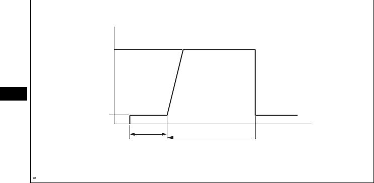
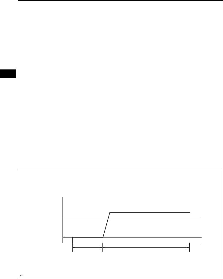
2. CATALYST MONITOR (ACTIVE AIR-FUEL RATIO |
|
|
|
CONTROL TYPE) |
|
|
|
|
|
|
|
|
NOTICE: |
|
|
|
This test will not be completed |
Vehicle Speed |
|
|
if the vehicle is driven at |
|
|
|
absolutely constant speed |
Between |
(6) |
such as with cruise control |
|
40 mph and 70 mph |
|
|
activated. |
|
|
||
(64 km/h and 113 km/h) |
|
|
|
ES
(5)
Idling
Ignition Switch OFF
 Time
Time
Warm up |
10 minutes |
(Note: Even when vehicle stops during driving pattern, test can be resumed)
A115372E50
(a) Preconditions
The monitor will not run unless:
• The MIL is OFF.
(b) Drive Pattern
(1) Connect the intelligent tester to the DLC3.
(2) Turn the ignition switch to the ON position.
(3) Turn the tester on.
(4) Clear the DTCs (if set) (See page ES-38).
(5) Start the engine and warm it up.
(6) Drive the vehicle at between 40 mph and 70 mph (64 km/h and 113 km/h) for at least 10 minutes.
(c) Monitor Status
Check the Readiness Monitor status displayed on the tester.
If the status does not switch to COMPL (complete), extend the driving time.
3.EVAP SYSTEM MONITOR (KEY OFF TYPE)
(a)Preconditions
The monitor will not run unless:
–The fuel tank is less than 90% full.
–The altitude is less than 8,000 ft. (2,450 m).
–The vehicle is stationary.
–The engine coolant temperature is between 4.4°C and 35°C (40°F and 95°F).
–The intake air temperature is between 4.4°C and 35°C (40°F and 95°F).
–Vehicle was driven in a city area (or on free-way) for 10 minutes or more.
2AZ-FE ENGINE CONTROL SYSTEM – SFI SYSTEM |
ES–29 |
|
(b)Monitor Conditions
(1)Turn the ignition switch off and wait for 6 hours. HINT:
Do not start the engine until checking Readiness Monitor status. If the engine is started, the step described above must be repeated.
(c)Monitor Status
(1)Connect the intelligent tester to the DLC3.
(2)Turn the ignition switch to the ON position.
(3)Turn the tester on.
(4)Check the Readiness Monitor status displayed
on the tester.
If the status does not switch to COMPL (complete), restart the engine, make sure that the preconditions have been met, and ES then perform the Monitor Conditions again.
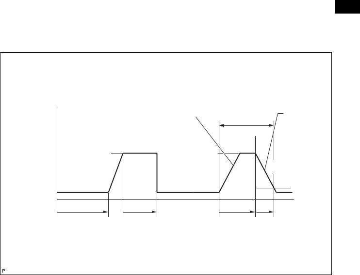
4.AIR-FUEL RATIO (A/F) AND HEATED OXYGEN (HO2) SENSOR MONITORS (ACTIVE AIR-FUEL RATIO CONTROL TYPE)
Monitor Drive Pattern |
|
|
|
|
|
ECT: 75°C (167°F) or more |
|
|
|
|
|
Vehicle Speed |
|
|
|
|
Accelerator |
|
|
At least 3 times |
Pedal |
||
|
|
Accelerator Pedal |
|||
|
|
Released |
|||
|
|
Depressed |
|
|
|
|
|
|
|
(Fuel-cut) |
|
|
|
|
|
|
|
Between 38 and 75 mph |
(6) |
(8) |
(9) |
|
|
(60 and 120 km/h) |
|
40 mph (64 km/h) |
|
||
|
|
|
|
||
|
|
or more |
|
(10) |
|
|
|
|
|
|
|
|
|
|
|
|
6 mph |
(5) |
|
(7) |
|
|
(10 km/h) |
Idling |
|
|
|
|
Time |
|
|
|
|
|
|
Warming up |
10 minutes |
10 seconds |
4 seconds |
||
|
or more |
or more |
or more |
|
|
|
|
|
|
|
A115374E09 |
(a)Preconditions
The monitor will not run unless:
–2 minutes or more have elapsed since the engine was started.
–The Engine Coolant Temperature (ECT) is 75°C (167°F) or more.
–Cumulative driving time at a vehicle speed of 30 mph (48 km/h) or more exceeds 6 minutes.
–Air-fuel ratio feedback control is performed.
ES–30
ES
2AZ-FE ENGINE CONTROL SYSTEM – SFI SYSTEM
(b)Drive Pattern for front A/F sensor and HO2 sensor
(1)Connect the intelligent tester to the DLC3.
(2)Turn the ignition switch to the ON position.
(3)Turn the tester on.
(4)Clear the DTCs (See page ES-38).
(5)Start the engine, and warm it up until the ECT reaches 75°C (167°F) or higher
(6)Drive the vehicle at between 38 mph (60 km/h) and 75 mph (120 km/h) for at least 10 minutes.
(7)Change the transmission to the 2nd gear.
(8)Accelerate the vehicle to 40 mph (64 km/h) or more by depressing the accelerator pedal for at least 10 seconds.
(9)Soon after performing step (8) above, release the accelerator pedal for at least 4 seconds
without depressing the brake pedal, in order to execute fuel-cut control.
(10)Allow the vehicle to decelerate until the vehicle speed declines to less than 6 mph (10 km/h).
(11)Repeat steps from (8) through (10) above at least 3 times in one driving cycle.
(c)Monitor Status
(1)Check the Readiness Monitor status displayed on the tester.
(2)If the status does not switch to COMPL (complete), make sure that the preconditions have been met, and then perform steps from (5) through (11) in the Drive Pattern above.
5.AIR-FUEL RATIO (A/F) AND HEATED OXYGEN (HO2) SENSOR HEATER MONITORS (FRONT A/F AND REAR HO2 SENSOR TYPE)
Vehicle Speed |
|
|
(7) |
25 mph (40 km/h) |
|
(6) |
|
Idling |
|
Ignition Switch OFF |
|
10 minutes or more |
2 minutes or more |
|
A121604E07 |
 Loading...