


 Loading...
MASTER SETUP UNIT
MSU-700A
MAINTENANCE MANUAL Part 1 1st Edition
Serial No. 15001 and Higher

!WARNING
This manual is intended for qualified service personnel only.
To reduce the risk of electric shock, fire or injury, do not perform any servicing other than that contained in the operating instructions unless you are qualified to do so. Refer all servicing to qualified service personnel.
!WARNUNG
Die Anleitung ist nur für qualifiziertes Fachpersonal bestimmt.
Alle Wartungsarbeiten dürfen nur von qualifiziertem Fachpersonal ausgeführt werden. Um die Gefahr eines elektrischen Schlages, Feuergefahr und Verletzungen zu vermeiden, sind bei Wartungsarbeiten strikt die Angaben in der Anleitung zu befolgen. Andere als die angegeben Wartungsarbeiten dürfen nur von Personen ausgeführt werden, die eine spezielle Befähigung dazu besitzen.
!AVERTISSEMENT
Ce manual est destiné uniquement aux personnes compétentes en charge de l’entretien. Afin de réduire les risques de décharge électrique, d’incendie ou de blessure n’effectuer que les réparations indiquées dans le mode d’emploi à moins d’être qualifié pour en effectuer d’autres. Pour toute réparation faire appel à une personne compétente uniquement.
MSU-700A MMP1
CAUTION
Danger of explosion if battery is incorrectly replaced.
Replace only with the same or equivalent type recommended by the manufacturer.
Dispose of used batteries according to the manufacturer’s instructions.
Vorsicht!
Explosionsgefahr bei unsachgemäßem Austausch der Batterie.
Ersatz nur durch denselben oder einen vom Hersteller empfohlenen ähnlichen Typ.
Entsorgung gebrauchter Batterien nach Angaben des Herstellers.
ATTENTION
Il y a danger d’explosion s’il y a remplacement incorrect de la batterie.
Remplacer uniquement avec une batterie du même type ou d’un type équivalent recommandé par le constructeur.
Mettre au rebut les batteries usagées conformément aux instructions du fabricant.
ADVARSEL!
Lithiumbatteri-Eksplosionsfare ved fejlagtig håndtering.
Udskiftning må kun ske med batteri af samme fabrikat og type.
Levér det brugte batteri tilbage til leverandøren.
Voor de klanten in Nederland
Dit apparaat bevat een MnO2-Li batterij voor memory back-up.
Raadpleeg uw leverancier over de verwijdering van de batterij op het moment dat u het apparaat bij einde levensduur afdankt.
Gooi de batterij niet weg. maar lever hem in als KCA.
Bij dit produkt zijn batterijen geleverd. Wanneer deze leeg zijn, moet u ze niet weggooien maar inleveren als KCA.
MSU-700A MMP1 |
1 (P) |
Table of Contents
Manual Structure
Purpose of this manual ........................................................................................ |
2 (E) |
Related manuals ................................................................................................... |
2 (E) |
Contents ............................................................................................................... |
2 (E) |
1. |
Installation Overview |
|
|
1-1. |
Power Supply ........................................................................................ |
1-1 (E) |
|
|
1-1-1. Voltage and Power Requirements ........................................ |
1-1 (E) |
|
|
1-1-2. |
Power Cord ........................................................................... |
1-1 (E) |
1-2. |
Connectors and Cable ........................................................................... |
1-2 (E) |
|
|
1-2-1. |
Connector Input/Output Signals ........................................... |
1-2 (E) |
|
1-2-2. |
Connection Connector .......................................................... |
1-4 (E) |
|
1-2-3. Wiring Diagram for Cable ................................................... |
1-4 (E) |
|
1-3. |
Installation ............................................................................................. |
1-5 (E) |
|
|
1-3-1. |
Installation Conditions ......................................................... |
1-5 (E) |
|
1-3-2. |
Outer Dimensions ................................................................. |
1-5 (E) |
1-4. Instance of System Configuration ......................................................... |
1-6 (E) |
||
|
1-4-1. BVP-900 Series Camera System .......................................... |
1-6 (E) |
|
|
1-4-2. HDC-700A Series Camera System ...................................... |
1-8 (E) |
|
2. |
Service Overview |
|
2-1. |
Location of Printed Wiring Boards ....................................................... |
2-1 (E) |
2-2. |
Removing/Installing the Cabinet ........................................................... |
2-2 (E) |
2-3. |
Circuit Description ................................................................................ |
2-3 (E) |
2-4. |
Function of Internal Switches ............................................................... |
2-4 (E) |
2-5. |
Replacing the Backup Battery ............................................................... |
2-5 (E) |
2-6. |
Notes on Repair Parts ............................................................................ |
2-5 (E) |
3. |
Spare Parts |
|
4 Overall Block Diagram
Overall ......................................................................................................... |
4-2 |
MSU-700A MMP1 |
1 (E) |

Manual Structure
Purpose of this manual
This manual is the maintenance manual part 1 of Master Setup Unit MSU-700A. This manual is intended for use by trained system and service engineers, and provides the installation and maintenance information that is necessary at the time of primary service.
Related manuals
Besides this “maintenance manual part 1”, the following manuals are available for this unit.
.Operation Manual (Supplied with the MSU-700A)
This manual is necessary for application and operation of this unit.
.Maintenance Manual Part 2 (Available on request)
This manual describes the information items on maintenance, and items that premise the service based on the components parts such as service information, semiconductor pin assignments, block diagrams, schematic diagrams and board layouts.
If this manual is required, please contact your local Sony Sales Office/Service Center.
.System Manual (Available on request)
This manual is necessary for connection and operation of video camera and other peripheral equipment.
If this manual is required, please contact your local Sony Sales Office/Service Center.
Contents
The followings are summaries of all the sections for understanding the contents of this manual.
Section 1 Installation Overview
Describes information about power conditions, connector input/output signals and instance of system configuration.
Section 2 Service Overview
Describes information about board locations, circuit description and function of internal switches.
Section 3 Spare Parts
Describes spare parts list such as cabinet, knobs and key tops used in this unit.
Section 4 Overall Block Diagram
Describes overall block diagram.
2 (E) |
MSU-700A MMP1 |
Section 1
Installation Overview
1-1. Power Supply
1-1-1. Voltage and Power Requirements
Power voltage: |
AC 100 to 240 V |
Power frequency: |
50 Hz or 60 Hz |
Power consumption: |
0.45 A |
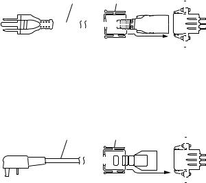
1-1-2. Power Cord
w
. Never use an injured power cord. If not, it may cause of fire or electric shock.
. The power cord is not supplied in this unit. Use the specified power cord when connecting.
Power cord for the customer in U.S.A. and Canada.
1 Power cord 125V 10A (approx. 2.4 m) |
! 1-551-812-11 |
2 Plug holder (Black) |
2-990-242-01 |
If the specified power cord is required, contact your local Sony Sales Office/Service Center.
|
|
|
|
|
|
|
|
|
1 |
|
2 |
|
|
|
|
|
|
|
|
AC inlet |
|||||
|
|
|
|
|
|
|
|
|
|
|
|
|
|
|
|
|
|
|
|
|
|||||
|
|
|
|
|
|
|
|
|
|
|
|
|
|
|
|
|
|
|
|
|
|||||
|
|
|
|
|
|
|
|
|
|
|
|
|
|
|
|
|
|
|
|
|
|
|
|
|
|
|
|
|
|
|
|
|
|
|
|
|
|
|
|
|
|
|
|
|
|
|
|
|
|
|
|
|
|
|
|
|
|
|
|
|
|
|
|
|
|
|
|
|
|
|
|
|
|
|
|
|
|
|
|
|
|
|
|
|
|
|
|
|
|
|
|
|
|
|
|
|
|
|
|
|
|
|
|
|
|
|
|
|
|
|
|
|
|
|
|
|
|
|
|
|
|
|
|
|
|
|
|
|
|
Power cord for the customer in the United Kingdom.
1 DK-2401(UK) Power cord 250V 10A (approx. 2.4 m)
2 Plug holder (Black) 2-990-242-01 Plug holder is included in DK-2401(UK).
1 |
2 |
|
|
|
|
|
|
|
|
|
|
|
AC inlet |
||||||
|
|
|
|
|
|
|
|
|
|
|
|
|
|
||||||
|
|
|
|
|
|
|
|
|
|
|
|
||||||||
|
|
|
|
|
|
|
|
|
|
|
|
|
|
|
|
|
|
|
|
|
|
|
|
|
|
|
|
|
|
|
|
|
|
|
|
|
|
|
|
|
|
|
|
|
|
|
|
|
|
|
|
|
|
|
|
|
|
|
|
|
|
|
|
|
|
|
|
|
|
|
|
|
|
|
|
|
|
|
|
|
|
|
|
|
|
|
|
|
|
|
|
|
|
|
|
|
|
|
|
|
|
|
|
|
|
|
|
|
|
|
|
|
|
|
|
|
|
|
|
|
|
|
|
|
|
|
|
|
|
|
|
|
|
|
|
|
|
|
|
|
|
|
|
|
|
|
|
|
|
|
|
|
|
|
|
|
|
|
|
|
|
|
|
|
|
|
|
|
|
|
|
|
|
|
|
|
|
|
|
MSU-700A MMP1 |
1-1 (E) |
1-1. Power Supply
1-2. Connectors and Cable
Power cord for the customer in the Europe except the United Kingdom.
1 DK-2401(AE) Power cord 250V 10A (approx. 2.4 m) |
|
|
|
||||||||||||||||
2 Plug holder (Brown) |
3-613-640-01 |
|
|
|
|
|
|||||||||||||
Plug holder is included in DK-2401(AE). |
|
|
|
|
|
|
|
|
|
|
|
|
|
|
|
|
|
|
|
|
|
|
|
|
|
|
|
|
|
|
|
|
|
|
|
|
|
|
|
1 |
2 |
|
|
|
|
|
|
|
|
|
|
|
AC inlet |
||||||
|
|
|
|
|
|
|
|
|
|
|
|
|
|
||||||
|
|
|
|
|
|
|
|
|
|
|
|
||||||||
|
|
|
|
|
|
|
|
|
|
|
|
|
|
|
|
|
|
|
|
|
|
|
|
|
|
|
|
|
|
|
|
|
|
|
|
|
|
|
|
|
|
|
|
|
|
|
|
|
|
|
|
|
|
|
|
|
|
|
|
|
|
|
|
|
|
|
|
|
|
|
|
|
|
|
|
|
|
|
|
|
|
|
|
|
|
|
|
|
|
|
|
|
|
|
|
|
|
|
|
|
|
|
|
|
|
|
|
|
|
|
|
|
|
|
|
|
|
|
|
|
|
|
|
|
|
|
|
|
|
|
|
|
|
|
|
|
|
|
|
|
|
|
|
|
|
|
|
|
|
|
|
|
|
|
|
|
|
|
|
If the unit is used in the area except above, contact your local Sony Sales Office/Service Center.
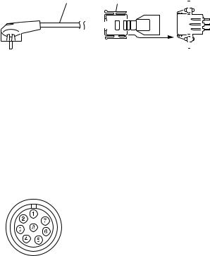
1-2. Connectors and Cable
1-2-1. Connector Input/Output Signals
REMOTE (8-pin, Female)
AUX
CCU/CNU
|
< Rear panel > |
|
|
|
|
Pin No. |
Signal |
Specifications |
|
|
|
1 |
TX (+) |
MSU Serial data |
|
|
|
2 |
TX (_) |
MSU Serial data |
|
|
|
3 |
RX (+) |
CCU/CNU/AUX Serial data |
|
|
|
4 |
RX (_) |
CCU/CNU/AUX Serial data |
|
|
|
5 |
TX GND |
GND for TX |
|
|
|
6 |
POWER (+) |
Not used |
|
|
|
7 |
POWER (_) |
Not used |
|
|
|
8 |
SPARE |
—— |
|
|
|
|
CHASSIS GND |
Chassis GND |
|
|
|
1-2 (E) |
MSU-700A MMP1 |

1-2. Connectors and Cable
I/O PORT (50-pin, Female)
1 |
|
2 |
|
3 |
|
4 |
|
5 |
|
6 |
|
7 |
|
8 |
9 |
|
10 |
11 |
12 |
13 |
14 |
15 |
16 |
17 |
|||||||
18 |
19 |
20 |
21 |
22 |
23 |
24 |
25 |
26 |
27 |
28 |
29 |
30 |
31 |
32 |
33 |
||||||||||||||||
34 |
35 |
36 |
37 |
38 |
39 |
40 |
41 |
42 |
43 |
44 |
45 |
46 |
47 |
48 |
49 |
50 |
|||||||||||||||
< Rear panel >
Pin No. |
Signal |
Specifications |
1 |
EXT I/O-00 |
INPUT/OUTPUT PORT (*1) |
2 |
EXT I/O-03 |
INPUT/OUTPUT PORT (*1) |
3 |
EXT I/O-06 |
INPUT/OUTPUT PORT (*1) |
4 |
EXT I/O-11 |
INPUT/OUTPUT PORT (*1) |
5 |
EXT I/O-14 |
INPUT/OUTPUT PORT (*1) |
6 |
EXT I/O-17 |
INPUT/OUTPUT PORT (*1) |
7 |
EXT I/O-22 |
INPUT/OUTPUT PORT (*1) |
8 |
EXT I/O-25 |
INPUT/OUTPUT PORT (*1) |
9 |
EXT I/O-30 |
INPUT/OUTPUT PORT (*1) |
10 |
EXT I/O-33 |
INPUT/OUTPUT PORT (*1) |
11 |
EXT I/O-36 |
INPUT/OUTPUT PORT (*1) |
12 |
EXT I/O-41 |
OUTPUT PORT (*1) |
13 |
EXT I/O-44 |
INPUT PORT (*1) |
14 |
EXT I/O-47 |
INPUT PORT (*1) |
15 |
+12 V OUT |
Utility power 12 V |
|
|
|
16 |
+12 V OUT |
Utility power 12 V |
|
|
|
17 |
SPARE |
No connection |
|
|
|
18 |
EXT I/O-01 |
INPUT/OUTPUT PORT (*1) |
19 |
EXT I/O-04 |
INPUT/OUTPUT PORT (*1) |
20 |
EXT I/O-07 |
INPUT/OUTPUT PORT (*1) |
21 |
EXT I/O-12 |
INPUT/OUTPUT PORT (*1) |
22 |
EXT I/O-15 |
INPUT/OUTPUT PORT (*1) |
23 |
EXT I/O-20 |
INPUT/OUTPUT PORT (*1) |
24 |
EXT I/O-23 |
INPUT/OUTPUT PORT (*1) |
25 |
EXT I/O-26 |
INPUT/OUTPUT PORT (*1) |
Pin No. |
Signal |
Specifications |
26 |
EXT I/O-31 |
INPUT/OUTPUT PORT (*1) |
27 |
EXT I/O-34 |
INPUT/OUTPUT PORT (*1) |
28 |
EXT I/O-37 |
INPUT/OUTPUT PORT (*1) |
29 |
EXT I/O-42 |
OUTPUT PORT (*1) |
30 |
EXT I/O-45 |
INPUT PORT (*1) |
31 |
+5 V OUT |
Utility power 5 V |
|
|
|
32GND (+5 V) GND for utility power 5 V
33GND (+12 V) GND for utility power 12 V
34 |
EXT I/O-02 |
INPUT/OUTPUT PORT (*1) |
35 |
EXT I/O-05 |
INPUT/OUTPUT PORT (*1) |
36 |
EXT I/O-10 |
INPUT/OUTPUT PORT (*1) |
37 |
EXT I/O-13 |
INPUT/OUTPUT PORT (*1) |
38 |
EXT I/O-16 |
INPUT/OUTPUT PORT (*1) |
39 |
EXT I/O-21 |
INPUT/OUTPUT PORT (*1) |
40 |
EXT I/O-24 |
INPUT/OUTPUT PORT (*1) |
41 |
EXT I/O-27 |
INPUT/OUTPUT PORT (*1) |
42 |
EXT I/O-32 |
INPUT/OUTPUT PORT (*1) |
43 |
EXT I/O-35 |
INPUT/OUTPUT PORT (*1) |
44 |
EXT I/O-40 |
OUTPUT PORT (*1) |
45 |
EXT I/O-43 |
OUTPUT PORT (*1) |
46 |
EXT I/O-46 |
INPUT PORT (*1) |
47 |
+5 V OUT |
Utility power 5 V |
|
|
|
48GND (+5 V) GND for utility power 5 V
49GND (+12 V) GND for utility power 12 V
50 |
SPARE |
No connection |
|
(*1) |
INPUT |
ON: 5 V |
|
|
OFF : |
0 V |
|
|
OUTPUT |
TTL LEVEL |
|
|
|
Darlington transistor drive |
|
|
|
One port: max 5 mA |
|
(VEXT: 1.5 V, RETX: 1.1 kZ) All ports total: max 60 mA
MSU-700A MMP1 |
1-3 (E) |
Loading...