


NSR-500
Table of contents
 Loading...
Network
Surveillance
4-272-495-18 (1)
Server
User’s Guide
Software Version 1.6.5 and Later
Before operating the unit, please read this manual thoroughly
and retain it for future reference.
NSR-500 Series
© 2011 Sony Corporation

Table of Contents
Chapter 1 Introduction
Overview...........................................................................................6
Features and Functions ..................................................................8
System Requirements ...................................................................11
Front (When the Front Cover and the HDD Cover are Opened) .......... 8
Rear ....................................................................................................... 9
Chapter 2
Administration Menu
Overview.........................................................................................12
Displaying the Administration Menu ...........................................12
Changing Initial Settings with the Setup Menu...........................13
Displaying Setup Menu ....................................................................... 13
Details on Setting Items ...................................................................... 13
Configuring Settings Related to Servers.....................................18
Installing Patch Files.....................................................................20
Saving and Restoring Configuration Data ..................................21
Saving Configuration Data.................................................................. 21
Periodically Saving Configuration Data.............................................. 22
Restoring Configuration Data ............................................................. 22
Exporting System Information .....................................................24
Installing Licenses.........................................................................24
Chapter 3 Basic Operation
2
Table of Contents
Overview.........................................................................................25
Logging On to the NSR .................................................................25
Basic Window Operations ............................................................27
Changing the Password................................................................30
Logging Off ....................................................................................31
Locking the NSR ............................................................................31
Shutting Down and Restarting the NSR ......................................32
Viewing Version Information ........................................................32

Chapter 4
Application Settings
Alarms and Events ........................................................................33
Displaying Configuration Window ...............................................34
Registering Devices ......................................................................35
Changing Registration Details............................................................. 35
Deleting Devices ................................................................................. 35
Settings Required when Using SNC-CS20/CM120/DS10/DM110/
DS60/DM160............................................................................. 36
Registering Device Groups ................................................................. 37
Details of Each Screen ........................................................................ 38
Configuring Camera Video Settings ............................................42
Configuring Camera Operations ..................................................46
Configuring Preset Positions ............................................................... 46
Configuring Camera Tours.................................................................. 47
Configuring Shadow Tours ................................................................. 48
Configuring Masks (Camera).............................................................. 49
Configuring Control Protocols for Analog Cameras........................... 50
Configuring Network Camera Control................................................ 51
Configuring Audio .............................................................................. 51
Settings Related to Monitoring.....................................................52
Configuring Monitor Layout Settings ................................................. 52
Assigning Cameras to Monitor Frames............................................... 58
Configuring Layout Tours................................................................... 58
Configuring Motion Detection Settings .......................................60
Using the Motion Detection Function of the Camera
(VMD (Camera)) ....................................................................... 60
Configuring Camera Tamper Detection and Audio Detection... 62
Configuring Edge Storage Settings.............................................63
Configuring Settings Related to Storage ....................................64
Configuring Storage Settings .............................................................. 64
Configuring Settings Related to Deleting Recording Data ................. 67
Configuring Recording Schedules...............................................70
Configuring Schedules Manually........................................................ 70
Configuring Alarm Recording and Event Recording.......................... 72
Configuring Sensor Inputs ...........................................................77
Changing Settings of Sensor Input Pins of NSR................................. 77
Changing Settings of Sensor Input Pins of Camera ............................ 77
Changing Settings of Sensor Input Pins of Barionet........................... 78
Adding Logical Sensor Input Pins to NSR.......................................... 78
Deleting Logical Sensor Input Pins Created for NSR......................... 79
Setting Items of the [Sensor In] Tab ................................................... 79
Configuring Alarm Output Settings .............................................80
Changing Settings of Alarm Output Pins of NSR............................... 80
Table of Contents
3

Changing Settings of Alarm Output Pins of Camera .......................... 80
Changing Settings of Alarm Output Pins of Barionet......................... 81
Setting Items of the [Alarm Out] Tab ................................................. 81
Configuring Action Settings .........................................................83
Manual Action..................................................................................... 83
Event/Alarm Actions........................................................................... 86
Configuring Mail Notification Settings ........................................90
Configuring System Alert Settings ..............................................91
Configuring Emergency Event Settings......................................92
Registering Users ..........................................................................93
User Levels and Permissions............................................................... 93
Configuring Default Access Permission ............................................. 93
Registering a User ............................................................................... 94
Changing User Settings ....................................................................... 94
Deleting a User.................................................................................... 94
Setting Items of the [User] Tab ........................................................... 95
Configuring the Duration to Rewind for Quick Playback...........96
Chapter 5
Operation and Control
Monitoring ......................................................................................97
Monitoring Live Images...................................................................... 97
Monitoring Using Layout Tours.......................................................... 98
Monitoring Audio from Cameras ........................................................ 98
Functions and Operating Procedure of Main Screen........................... 99
When a Click Action is Configured .................................................. 104
Monitor Frame................................................................................... 104
Controlling Cameras ...................................................................105
Performing Pan, Tilt, and Zoom Operations ..................................... 105
Using Camera Presets........................................................................ 106
Performing Camera Tours ................................................................. 107
Recording, Searching, and Playing Images ..............................107
Recording Live Images ..................................................................... 107
Playing Recorded Images.................................................................. 108
Searching Recorded Images .............................................................. 109
Playing Recorded Images from Search Results ................................ 109
Details of Search Window................................................................. 110
Deleting Recorded Images..........................................................112
Protecting Recorded Images ......................................................113
Exporting Recorded Images .......................................................113
Exporting Recorded Images .............................................................. 113
Exporting Recorded Images as Still Images...................................... 116
4
Table of Contents

Chapter 6 Appendix
System Administration................................................................117
Monitoring the Error Status............................................................... 117
Exporting Log Files........................................................................... 117
END-USER LICENSE AGREEMENT ...........................................119
Concerning GPL-LPGL................................................................120
MPEG-4 Video Patent Portfolio License....................................121
GNU GENERAL PUBLIC LICENSE .............................................121
Preamble............................................................................................ 121
TERMS AND CONDITIONS FOR COPYING, DISTRIBUTION
AND MODIFICATION........................................................... 122
END OF TERMS AND CONDITIONS ...........................................125
How to Apply These Terms to Your New Programs ........................ 125
GNU LESSER GENERAL PUBLIC LICENSE..............................126
Preamble............................................................................................ 126
TERMS AND CONDITIONS FOR COPYING, DISTRIBUTION
AND MODIFICATION........................................................... 127
END OF TERMS AND CONDITIONS ...........................................131
How to Apply These Terms to Your New Libraries ......................... 131
Index ............................................................................................133
Trademarks
• “IPELA” and are trademarks of Sony Corporation.
• The terms HDMI and HDMI High-Definition Multimedia Interface, and the HDMI Logo are trademarks or registered
trademarks of HDMI Licensing LLC in the United States and other countries.
• Other products or system names appearing in this document are trademarks or registered trademarks of their respective owners.
Further, the ® or ™ symbols are not used in the text.
Before using the unit, be sure to read “END-USER LICENSE AGREEMENT” in this manual.
The product’s specifications, and therefore the accuracy of this document, are subject
to change without notice.
Table of Contents
5
Chapter 1 Introduction
Introduction
Chapter
1
Overview
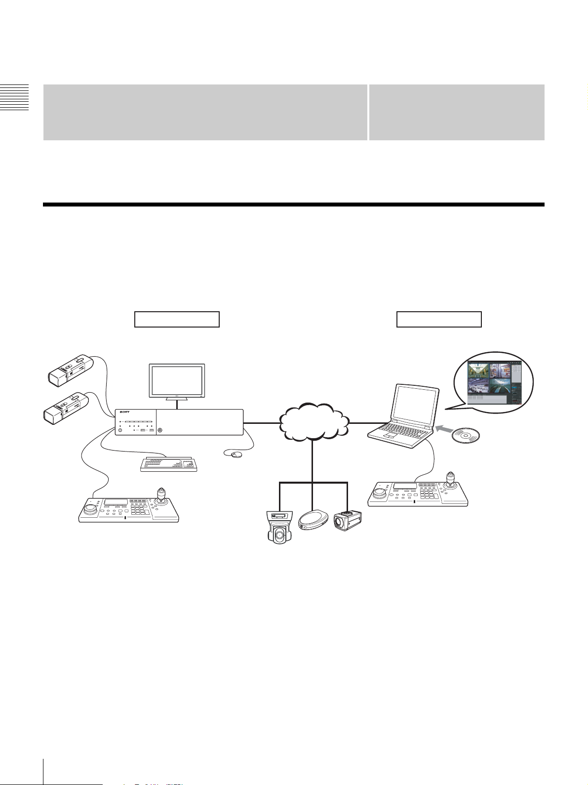
The NSR-500 series is a network surveillance server for network cameras. The NSR series allows you to monitor and
record JPEG, MPEG-4, and H.264 images from network cameras via the network. It also allows you to search and play
back recorded images, making the NSR a truly versatile monitoring system.
Machine room Surveillance room
Analog Camera
System Controller
1)
Monitor
Network
NSR-500 Series
Mouse
Keyboard
Surveillance cameras
1) The NSR requires an NSBK-EB05 (optional) expansion.
RealShot Manager Advanced
Client is used for surveillance
and configuration.
Windows PC
System Controller
RealShot Manager Advanced
Client Software
Installing
6
Overview

Control compatible cameras from remote
locations
You can pan, tilt, and perform zoom operations of
compatible cameras.
Compatible with analog cameras
You can monitor and record images from analog cameras
by connecting them directly to the unit
1) The NSR requires an NSBK-EB05 (optional) expansion.
1)
.
Slim type (2U), space-saving 19-inch rack
mounting model
With a purpose-built rack mounting kit, the unit can be
installed in a standard universal pitch EIA 19-inch rack.
For details on the rack mounting kit, contact your Sony
dealer.
High reliability
The NSR supports redundant configurations such as RAID
1)
5
and performs with high reliability. In a RAID 5
configuration, for example, the system can continue
functioning even if one of the hard disks develops a
malfunction. The NSR also supports uninterruptible power
supplies (UPS)
2)
, making them extremely reliable
systems.
1) RAID 5 is a system for dividing and storing data and parity
(error correcting codes) onto more than one hard disk drive.
Although this system allows continued operation should one
of the hard disks malfunction, it does not guarantee restoration
of lost data. In addition, due to high internal processing loads
during reconstruction after you replace the malfunctioned
hard disk, the unit may not be able to record images at the
configured recording rate while reconstruction is in progress.
2) If the power turns off suddenly during operation, the data may
be corrupted.
Chapter 1 Introduction
Protect data from power interruptions
If the power supply is interrupted while the unit is in
operation, data may be damaged. We recommend using an
uninterruptible power supply (UPS).
Other features
• Custom layout support allows you to display images in a
variety of different layouts in addition to standard 2 × 2
and 3 × 3 layouts.
• The NSR is capable of manual, scheduled, and alarm
recording, among others.
• Run searches for recorded images by camera name, date,
alarm, and other methods.
• Audio recording and playback
1)
are also supported from
compatible cameras.
• If a video loss occurs due to the network connection
being disrupted or an abnormal shutdown occurring,
video can be recorded to the camera’s Edge Storage,
allowing you to retrieve the data later after the system is
restored.
1) Optional audio amplifiers or speakers are required.
Overview
7
Features and Functions
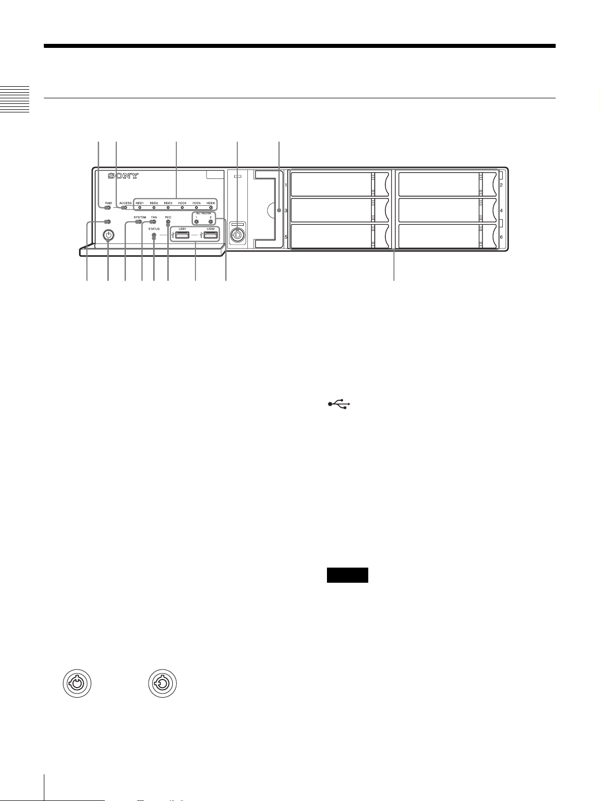
Front (When the Front Cover and the HDD Cover are Opened)
Chapter 1 Introduction
12 3 4 5
qd qs 90qaqf
A RAID LED
Lights green when the RAID configuration is
functioning properly.
Lights red if a fatal problem exists with the RAID due
to an internal HDD failure, for example.
Lights amber if the RAID is degraded or rebuilding.
B ACCESS LED
Blinks green when the HDDs are accessed.
C HDD LEDs (1 to 6)
Light green when the internal hard disk drives are
functioning properly.
Light red when failures or other problem occurs.
Also, light amber during the rebuilding of RAID.
D Lock
Use this in conjunction with the supplied HDD cover
key to lock the HDD cover.
When the HDD cover is locked, you cannot remove it.
The fan unit is also locked when the HDD cover is
locked.
When attaching the HDD cover, make sure the lock is
the unlocked state before you attach the cover.
You can distinguish the locked position from the
unlocked position by looking at the lock, as illustrated
below.
The HDD cover is
locked
E Fan unit
For details on maintenance, contact your Sony dealer.
The HDD cover is
unlocked
768
F HDDs
For details on maintenance, contact your Sony dealer.
G NETWORK LEDs (1 and 2)
Light green when there is a link to the network.
Blink amber when the network is being accessed.
H USB connectors (1 and 2)
Use these connectors to connect a USB mouse, USB
keyboard, USB flash memory device, USB CD/DVD
drive, or system controller (RM-NS1000) to the unit.
I REC LED
Lights red when recording images.
J STATUS LED
Indicates the recognition status of USB flash memory
devices.
If a device is recognized, this lights green.
If a device is not recognized, this lights red.
Caution
Do not remove the USB flash memory device while
the LED is blinking.
K FAN LED
Lights green when the internal fan is functioning
properly. Lights red when a fan failure occurs.
L SYSTEM LED
Blinks green while the unit is starting up and then
changes to always on when the unit has started.
During operation, this LED is lit green when the
system is functioning normally. When a system error
or other problem occurs, it lights red.
If this LED is lit red, contact your Sony dealer.
8
Features and Functions
M Power switch
Press this to turn on the unit.
If you press the power switch during operation, the
POWER LED blinks green for up to 3 seconds.
Pressing the power switch again during this time turns
off the unit.
If 3 seconds elapse without the power switch being
pressed while the POWER LED is blinking, the unit
does not turn off and operation continues.
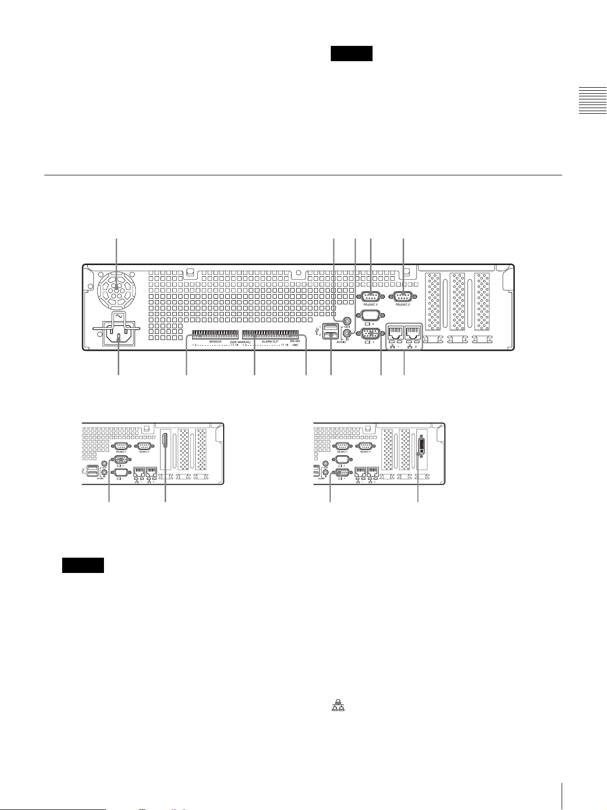
Rear
NSR-500
12345
Caution
Pressing and holding down the power switch
(approximately 5 seconds) turns off the unit forcefully.
N POWER LED
Lights green when the unit is turned on.
If you press the power switch during operation, the
POWER LED blinks green for up to 3 seconds.
Chapter 1 Introduction
qs 90qa
When NSBK-DH05 (optional) is mounted When NSBK-EB05 (optional) is mounted
qd7
A Fan
Caution
Take care not to obstruct the fan grille. If the grille is
obstructed, heat may build up in the unit, leading to
damage and/or fire.
B AUDIO OUT (line output) connector (stereo)
Use these connectors to output audio to a peripheral
audio device.
C AUDIO IN (microphone input) connector (used for
future expansion)
Use this connector to input audio from a peripheral
audio device, such as a microphone.
Plug-In Power microphones are supported.
D RS-232C 1 (UPS) connector
Use this connector to connect the control line of the
uninterruptible power supply (UPS).
E RS-232C 2 connector
Use this connector to connect analog cameras via the
analog camera input cable.
This connector cannot be used at the same time as the
I RS-422/485 connector.
For pin assignment details and wiring diagrams for
sensor inputs, refer to the Installation Manual
(separate document).
F LAN connectors (1 and 2)
Use these connectors to connect 10Base-T, 100BaseTX, or 1000Base-T network cables.
LAN1: Network cameras
768
qf7
1)
Features and Functions
9

LAN2: Network cameras1) (LAN2 can only be used
when using a different segment from LAN1.)
1) Connect remote clients to the network specified with the [Network
Interface for Remote Client] setting (either LAN1 or LAN2) in the
Server Configuration screen. For details, see “Configuring Settings
Related to Servers” (page 18).
Chapter 1 Introduction
Caution
• Do not configure LAN connectors 1 and 2 to the
same network segment.
• For details on using iSCSI storage, contact your
Sony dealer.
CAUTION
• For safety, do not connect the connector for
peripheral device wiring that might have excessive
voltage to the following ports.
- LAN1 connector
- LAN2 connector
• Follow the instructions for the above ports.
• When you connect the LAN cable of the unit to
peripheral device, use a shielded-type cable to
prevent malfunction due to radiation noise.
G Monitor connectors (1 and 2)
Use this connector to connect a monitor that supports
analog RGB input.
For connection details and wiring diagrams for sensor
inputs, refer to the Installation Manual (separate
document).
L Power supply connector
Use this connector to connect the power cord.
M HDMI monitor connector
Use this connector to connect a monitor that supports
HDMI input.
Monitor connector 2 and the HDMI monitor connector
cannot be used at the same time.
This connector can only be used when an NSBKDH05 (optional) is mounted.
N Analog camera cable input connector
Use this connector to connect the analog camera input
cable.
This connector can only be used when an NSBK-EB05
(optional) is mounted.
CAUTION
When you connect the analog camera input cable of
the unit to peripheral device, use the supplied cable to
prevent malfunction due to radiation noise.
Caution
If the optional NSBK-DH05 is installed, monitor
connector 1 will not be available for use. Only monitor
connector 2 will be available. Monitor connector 2 and
the HDMI monitor connector cannot be used at the
same time.
H USB connectors (1 and 2)
Use these connectors to connect a USB mouse, USB
keyboard, USB flash memory device, USB CD/DVD
drive, or system controller (RM-NS1000) to the unit.
I RS-422/485 connector
Use this connector to connect analog cameras via the
analog camera input cable.
This connector cannot be used at the same time as the
E RS-232C 2 connector.
For pin assignment details and wiring diagrams for
sensor inputs, refer to the Installation Manual
(separate document).
J ALARM OUT (alarm output) connector
Use this connector to connect the alarm output lines.
For connection details and a wiring diagram for alarm
output, refer to the Installation Manual (separate
document).
K SENSOR (sensor input) connector
Use this connector to connect the sensor input lines.
10
Features and Functions

System Requirements
- We do not recommend using USB bus power. Use an AC
power supply.
- We do not recommend using a USB hub.
The hardware required in order to use this unit are as
follows.
• Monitor
• Sony network cameras
• USB keyboard
•USB mouse
1)
2) 3)
5)
6)
or Sony analog cameras
3) 4)
•Network hub
• 1000Base-T/100Base-TX/10Base-T cable
• USB flash memory device
• USB CD/DVD drive
1) Computer displays that accept RGB input are supported.
The supported resolutions are as follows.
- Full High-Definition (1,920 × 1,080)
- WUXGA (1,920 × 1,200)
- Full Wide XGA (1,360 × 768)
- UXGA (1,600 × 1,200)
- SXGA (1,280 × 1,024)
- XGA (1,024 × 768)
When NSBK-DH05 (optional) is mounted
HDMI-compatible devices and computer displays that accept
RGB input are supported.
The supported resolutions are as follows.
- Full High-Definition (1,920 × 1,080)
- WUXGA (1,920 × 1,200)
- Full Wide XGA (1,360 × 768)
- UXGA (1,600 × 1,200)
- SXGA (1,280 × 1,024)
- XGA (1,024 × 768)
However, WUXGA is not supported on HDMI-compatible
devices.
2) Contact your dealer for details about compatible Sony
network cameras.
3) Refer to the release notes for details about compatible
cameras from other manufacturers.
4) The NSR requires an NSBK-EB05 (optional) expansion.
5) Use a USB keyboard with a cable. However, keys other than
the standard may not function. Wireless or infrared USB
keyboards may also not function properly.
6) Use a USB mouse with a cable. Wireless or infrared USB
mice may not function properly. Functions such as threebutton and wheel operations may also function improperly.
7) Required when backing up system information such as logs.
- This unit supports USB 2.0, Mass Storage class devices.
However, it does not support USB 2.0, Mass Storage class
HDDs. Be aware that errors may still occur when writing
data to a USB 2.0, Mass Storage class memory device,
depending on the type of device used. If errors occur when
writing data, use a USB flash memory device of a different
type. Only FAT-format USB flash memory devices are
supported.
8) The following restrictions apply.
- Supported media: CD-R, CD-RW, DVD-R, DVD+R,
DVD+R DL
- Format: ISO 9660 format (RockRidgeExtension/
JolietExtension)
- Use blank media or media that has previously been written
on using the NSR-500 series.
- Media that has been written on using equipment other than
the NSR-500 series is not supported.
- USB 1.1/2.0 supported.
7)
8)
Caution
Make sure that the connected network is secure when
operating this unit.
Chapter 1 Introduction
System Requirements
11
Administration Menu
Chapter 2
Administration Menu
Overview
The Administration Menu allows you to change settings
that were configured with the Setup Wizard when you
turned on the NSR for the first time, and also allows you to
perform configurations and operations related to the
server.
This chapter describes the following configurations and
operations for the Administration Menu.
• “Displaying the Administration Menu” (page 12)
• “Changing Initial Settings with the Setup Menu”
(page 13)
• “Configuring Settings Related to Servers” (page 18)
• “Installing Patch Files” (page 20)
• “Saving and Restoring Configuration Data” (page 21)
• “Exporting System Information” (page 24)
Chapter
2
Displaying the Administration Menu
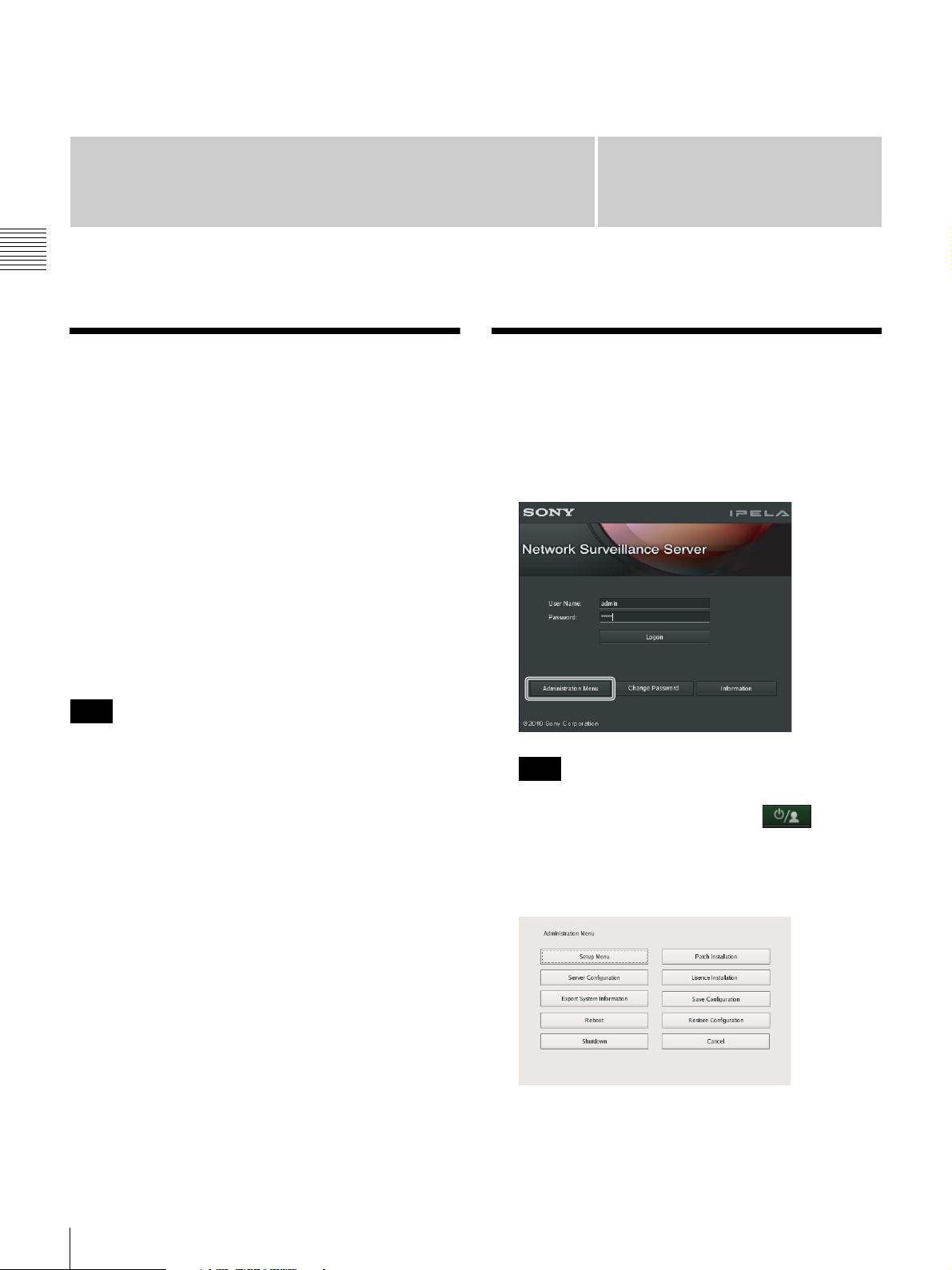
1
Enter the user name and password in the logon screen,
and click [Administration Menu].
Note
For details on restart and shutdown procedures, see
Chapter 3 “Shutting Down and Restarting the NSR”
(page 32).
Note
If you are already logged on to the NSR, you can
display the logon screen by clicking at the top
right of the Main screen and logging off from the
dialog box that appears.
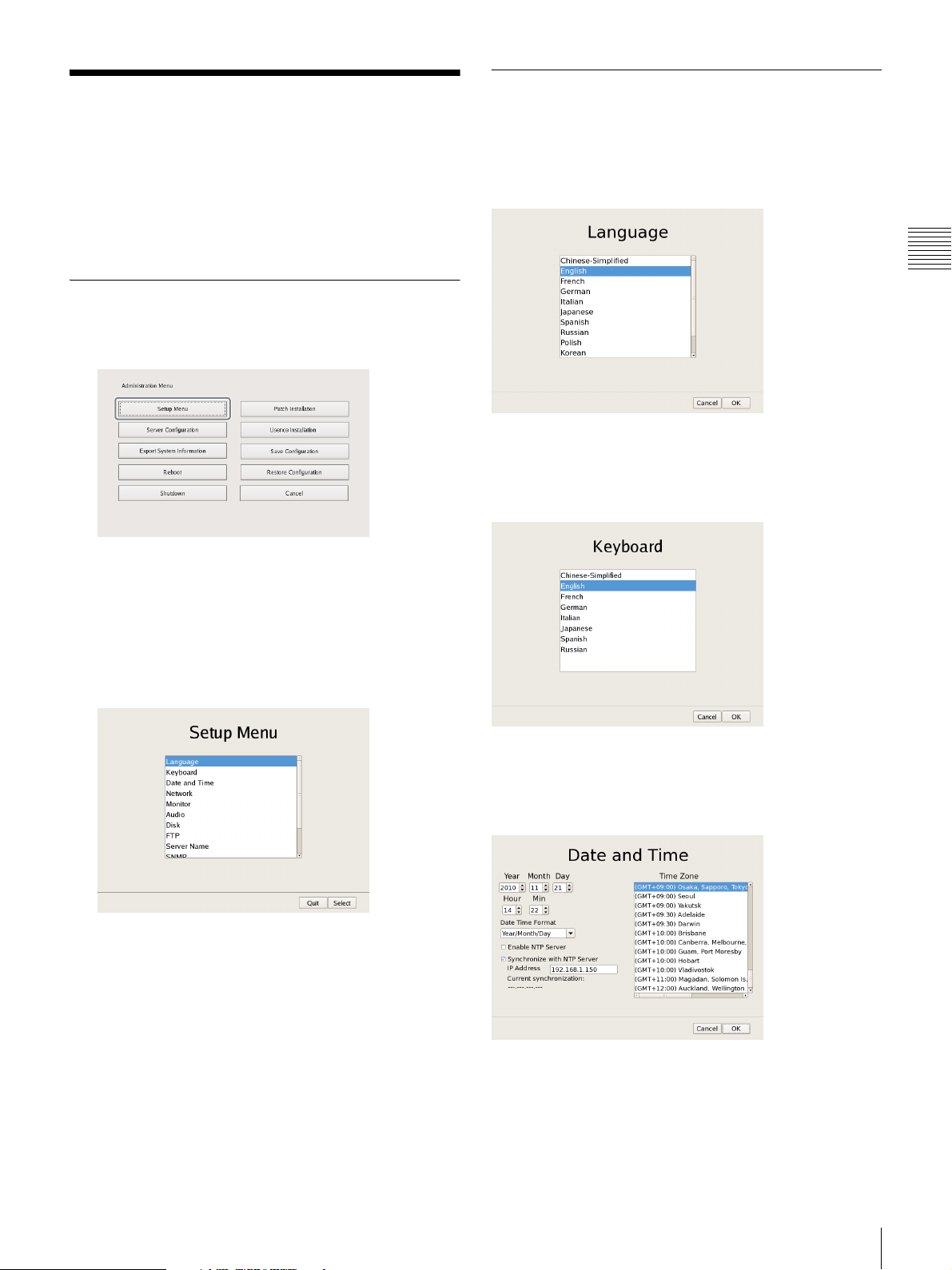
The Administration Menu screen appears.
12
Overview / Displaying the Administration Menu
Changing Initial Settings
Details on Setting Items
with the Setup Menu
Use the Setup Menu to change settings that were
configured with the Setup Wizard when you turned on the
NSR for the first time.
Displaying Setup Menu
1
Click [Setup Menu] in the Administration Menu.
The menu items of the Administration Menu differ
depending on the server and clients.
Setting Items of Language Screen
Select the language to display on the screens, and click
[OK].
Chapter 2
Administration Menu
Setting Items of Keyboard Screen
Select the language of the USB keyboard connected to
NSR, and click [OK].
The Setup Menu appears.
2
Select the item you want to configure, and click
[Select].
The screen corresponding to the item appears.
Setting Items of Date and Time Screen
Configure the date and time of the equipment, and click
[OK].
Year/Month/Day
Enter the date.
Hour/Min
Enter the time.
Changing Initial Settings with the Setup Menu
13
Date Time Format
Select the format for the date and time.
Enable NTP Server
Select the check box to enable the NTP server of NSR.
LAN2: Network cameras1) (LAN2 can only be used when
using a different segment from LAN1.)
1) Connect remote clients to the network specified with the [Network
Interface for Remote Client] setting (either LAN1 or LAN2) in the Server
Configuration screen. For details on the Server Configuration screen, see
“Configuring Settings Related to Servers” (page 18).
Caution
When the NTP server of NSR is enabled, enable
[Synchronize with NTP Server] as well, and configure
settings to obtain clock information from other NTP
Chapter 2
servers. If you do not configure the settings, the clock may
deviate dramatically.
Synchronize with NTP Server
Administration Menu
Select the check box to obtain the current time from
another NTP server.
IP Address
Enter the IP address of the NTP server from which to
obtain the information.
Current Synchronization
This displays the IP address of the NTP server from
which the current information is being obtained.
Time Zone
Select the region to configure the date and time.
Note
There is no setting for enabling or disabling daylight
saving time. If you select a time zone in which daylight
saving time is observed, the clock is adjusted
automatically for daylight saving time.
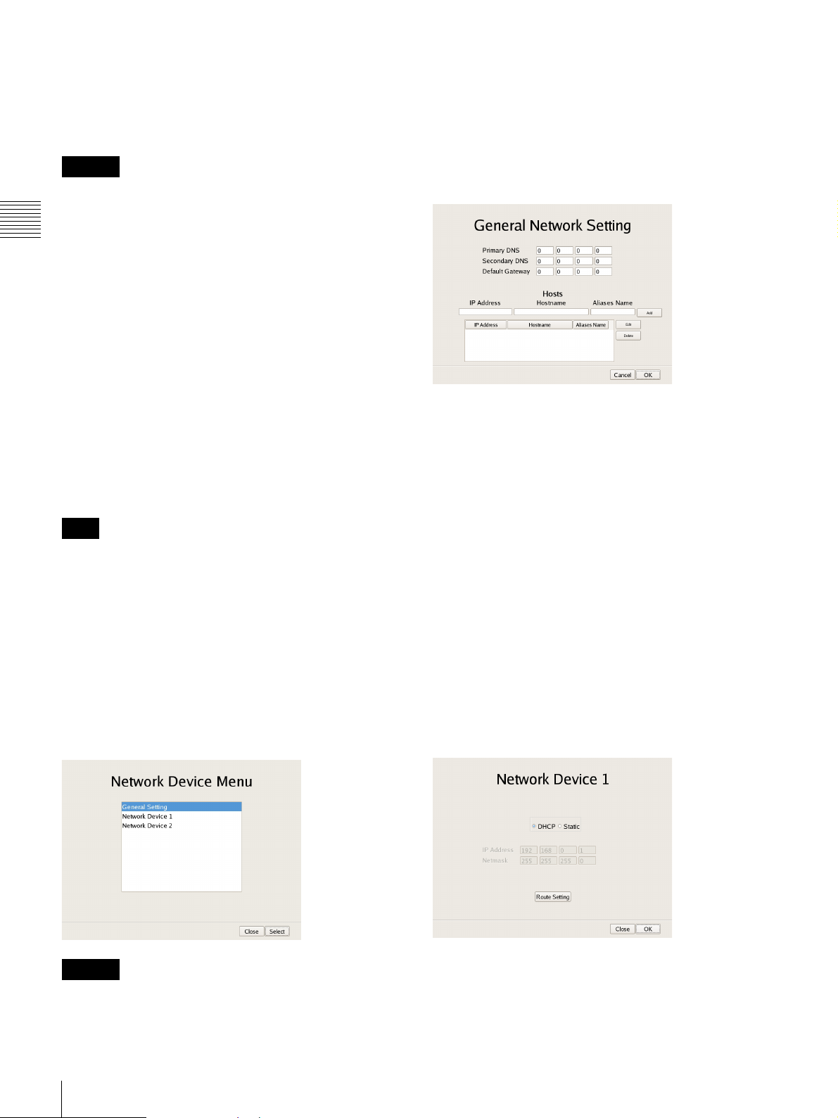
xSetting Items of General Network Screen
Configure each item, and click [OK].
Primary DNS
Enter the IP address for the primary DNS (Domain Name
Server).
Do not enter this if there is no primary DNS, or if it is not
required.
Secondary DNS
Enter the IP address for the secondary DNS. Do not enter
this if there is no secondary DNS, or if it is not required.
Default Gateway
Enter the IP address for the default gateway. Do not enter
this is if there is only a local network or there is no need to
connect to another network.
Setting Items of Network Device Menu
Screen
The network settings consist of “General Setting” for
setting general settings, and “Network Device 1 to 2” for
setting LAN connectors.
Select the network you want to configure, and click [OK].
Caution
Connect the following devices to the LAN connectors.
LAN1: Network camera
1)
Hosts
If host name registration is necessary, enter a combination
of the IP address and host name, and click [Add] to add the
host to the list.
xSetting Items of Network Device 1 to 2
Configure each item, and click [OK].
Configure the settings as follows in accordance with your
environment.
14
Changing Initial Settings with the Setup Menu
To use a DHCP to obtain the address setting automatically:
Select [DHCP].
To configure the address setting manually:
1 Click [Static].
2 Enter the following address.
IP Address
Enter the IP address.
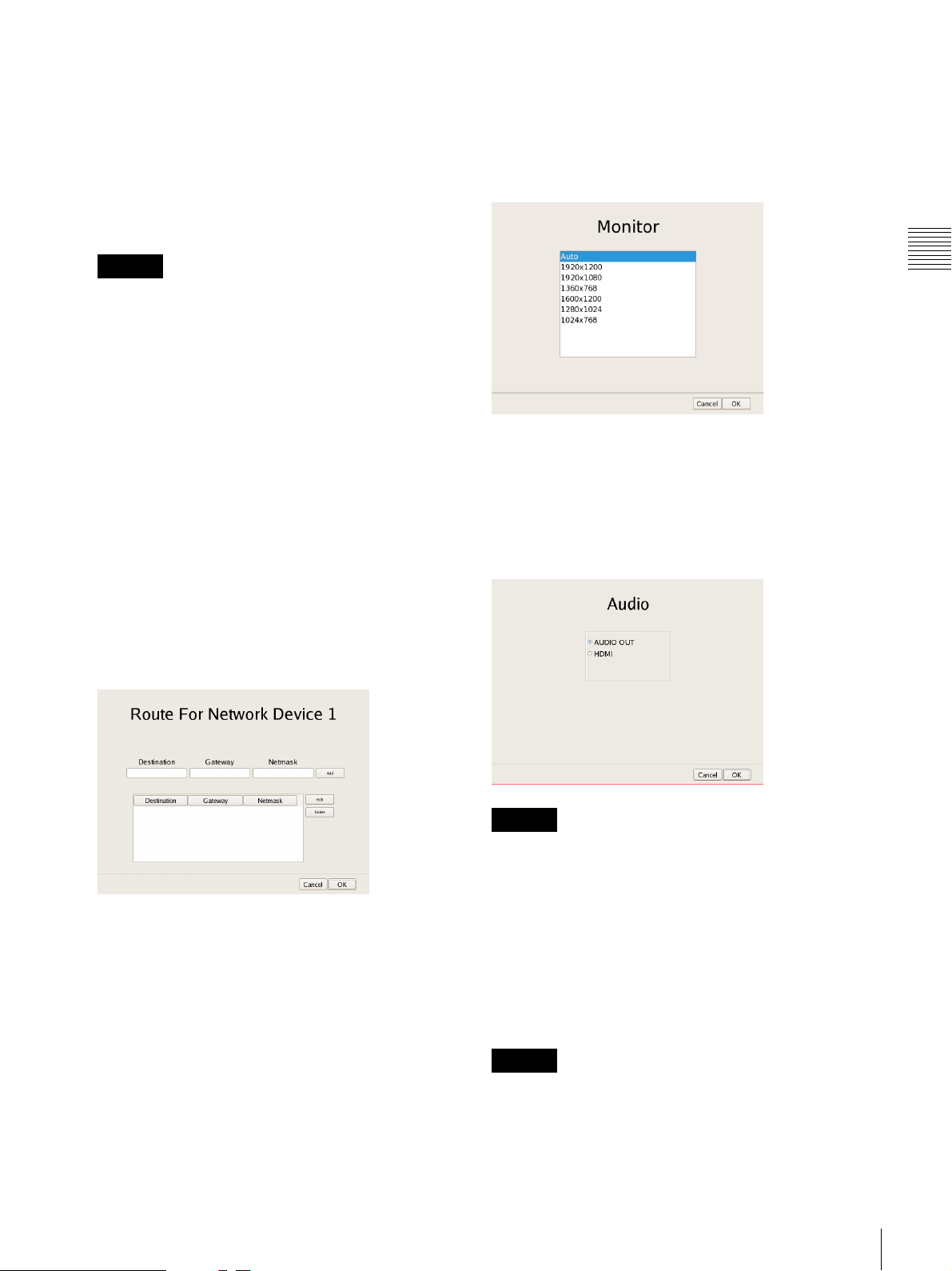
Setting Items of Monitor Screen
Select the resolution of the monitor connected to the unit,
and click [OK].
If you select [Auto], the maximum resolution of the
connected monitor will be detected and selected
automatically.
Caution
• Before you enter the IP address, make sure there is
no machine that uses the same value on the same
network. Even if a machine that uses the same value
does exist, an error message will not be displayed.
However, be careful because more than one machine
using the same value will result in incorrect
operation.
• Do not set an IP address that is prohibited under the
IP address assignment rules.
Example: 224.0.0.0 to 255.255.255.255
0.0.0.0
127.0.0.1, etc.
Netmask
Enter the subnet mask.
Route Setting
Click this when you need to configure the route to
another network.
Configure the settings as follows on the Route For
Network Device 1 screen that appears.
Chapter 2
Administration Menu
Setting Items of Audio Screen
Select the audio connector you want to use, and click
[OK].
When using audio output from an HDMI monitor, select
[HDMI]. ([HDMI] can only be selected when an optional
NSBK-DH05 is installed.)
1 Enter the address, gateway, and netmask of the
other network to which to connect, and click [Add]
to add the network to the list.
For details, contact the administrator of the network
to which you will connect.
2 Click [OK].
Caution
When removing an NSBK-DH05 from the main unit, be
sure to check that AUDIO OUT is in use. If the
NSBK-DH05 is removed from the main unit while
[HDMI] is selected, audio will not be output from AUDIO
OUT until it is reselected. In such cases, reselect [AUDIO
OUT] in the Audio screen.
Setting Items of Disk Screen
Configure iSCSI settings.
Caution
Contact your Sony dealer when using iSCSI.
Changing Initial Settings with the Setup Menu
15
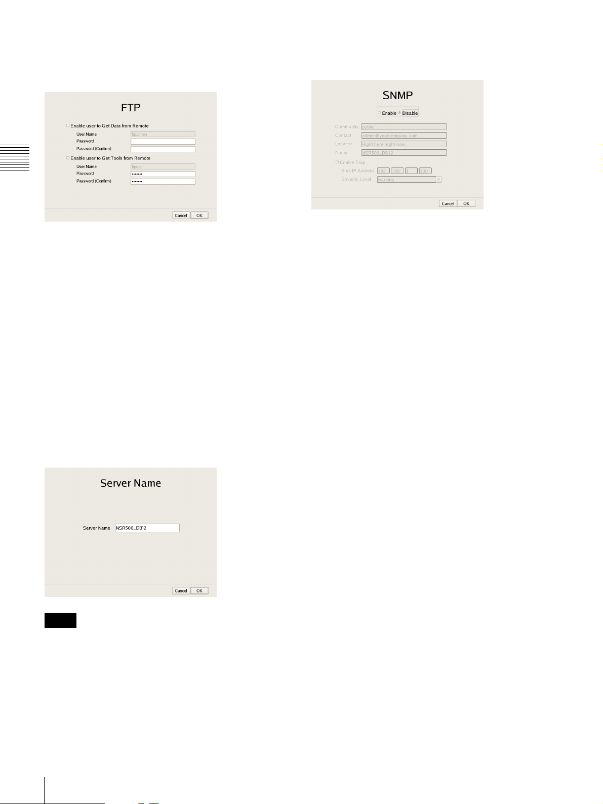
Setting Items of FTP Screen
Configure each of the items when you want to enable the
FTP server, and click [OK].
Chapter 2
Administration Menu
Enable user to Get Data from Remote
This function is used for service and maintenance.
Enable user to Get Tools from Remote
Select the check box to enable remote client downloading
of tools, operating manuals, and other documents using
FTP.
This is enabled under default settings.
User Name
This displays the user name. The user name is
“ftptool.”
It cannot be changed.
Password
Enter the password. The default password is “ftptool.”
Setting Items of Server Name Screen
Enter the server name of NSR, and click [OK].
Setting Items of SNMP Screen
Configure each item related to SNMP, and click [OK].
Enable
Select this to enable the SNMP agent function.
Disable
Select this to disable the SNMP agent function.
Community
Enter the SNMP community name.
Contact
Enter the contact.
Normally, enter the mail address of the system
administrator.
Location
Enter the installation location of NSR.
Name
Enter the name of the NSR unit.
Enable Trap
Select this to enable SNMP trap transmission.
Notes
• If you do not set a server name, a default name (e.g.,
NSR500_DB12) to which the last four digits of this
unit’s LAN1 MAC address is appended is set.
• Do not use spaces when entering the server name.
Sink IP Address
Enter the destination IP address for SNMP traps.
Severity Level
Select the severity level for SNMP trap transmission.
An SNMP trap will be sent when severity levels meet or
exceed this setting.
For details on SNMP traps, contact your Sony dealer.
16
Changing Initial Settings with the Setup Menu
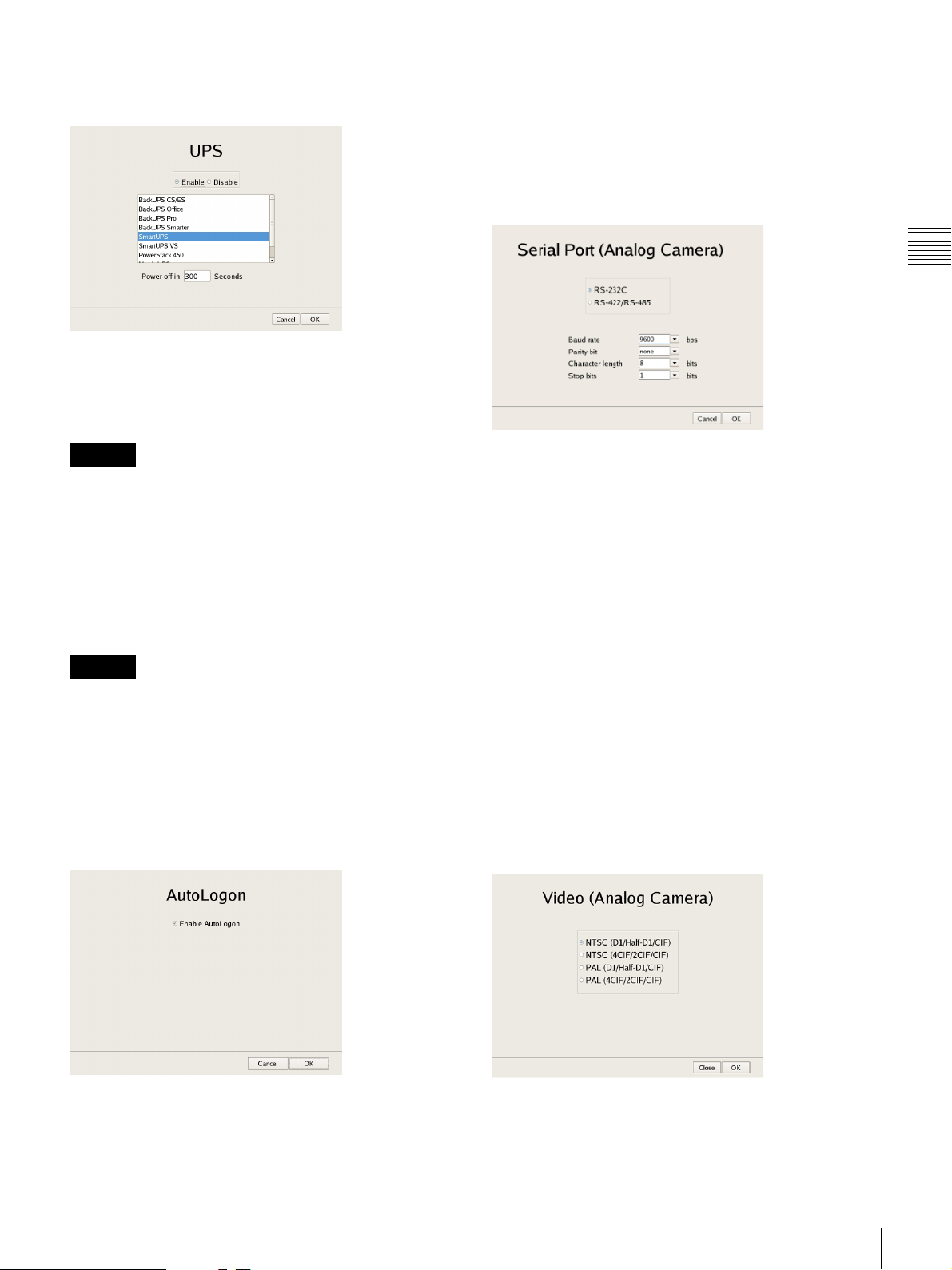
Setting Items of UPS Screen
Configure settings related to UPS, and click [OK].
Enable
Select this when using a UPS.
If this is selected, select the type of UPS to be used from a
list of UPS.
Setting Items of Serial Port (Analog
Camera) Screen
Configure settings related to the analog camera
connection.
Configure each item, and click [OK].
(This screen only appears when an optional NSBK-EB05
is installed.)
Chapter 2
Administration Menu
Caution
If the power turns off suddenly during operation, the data
may be corrupted.
Disable
Select this when not using a UPS.
Power off in XXX Seconds
Enter the time from when a power cut is detected until
shutdown to start.
Caution
For details on automatic startup after power is restored,
contact your dealer.
Setting Items of Auto Logon Screen
When you want to enable the auto logon function, select
the [Enable Auto Logon] check box, and click [OK].
For details on the auto logon function, refer to “Logging
On to the NSR” (page 25).
Serial standard (RS-485, RS-422, RS-232C)
Select the serial standard for connecting to the analog
camera you want to control.
Baud rate
Select the communication baud rate.
Parity bit
Select the parity bit.
Character length
Select the character length.
Stop bits
Select the stop bits.
Setting Items of Video (Analog Camera)
Screen
Select the video format for the analog camera to be
connected, and click [OK].
(This screen only appears when an optional NSBK-EB05
is installed.)
Changing Initial Settings with the Setup Menu
17
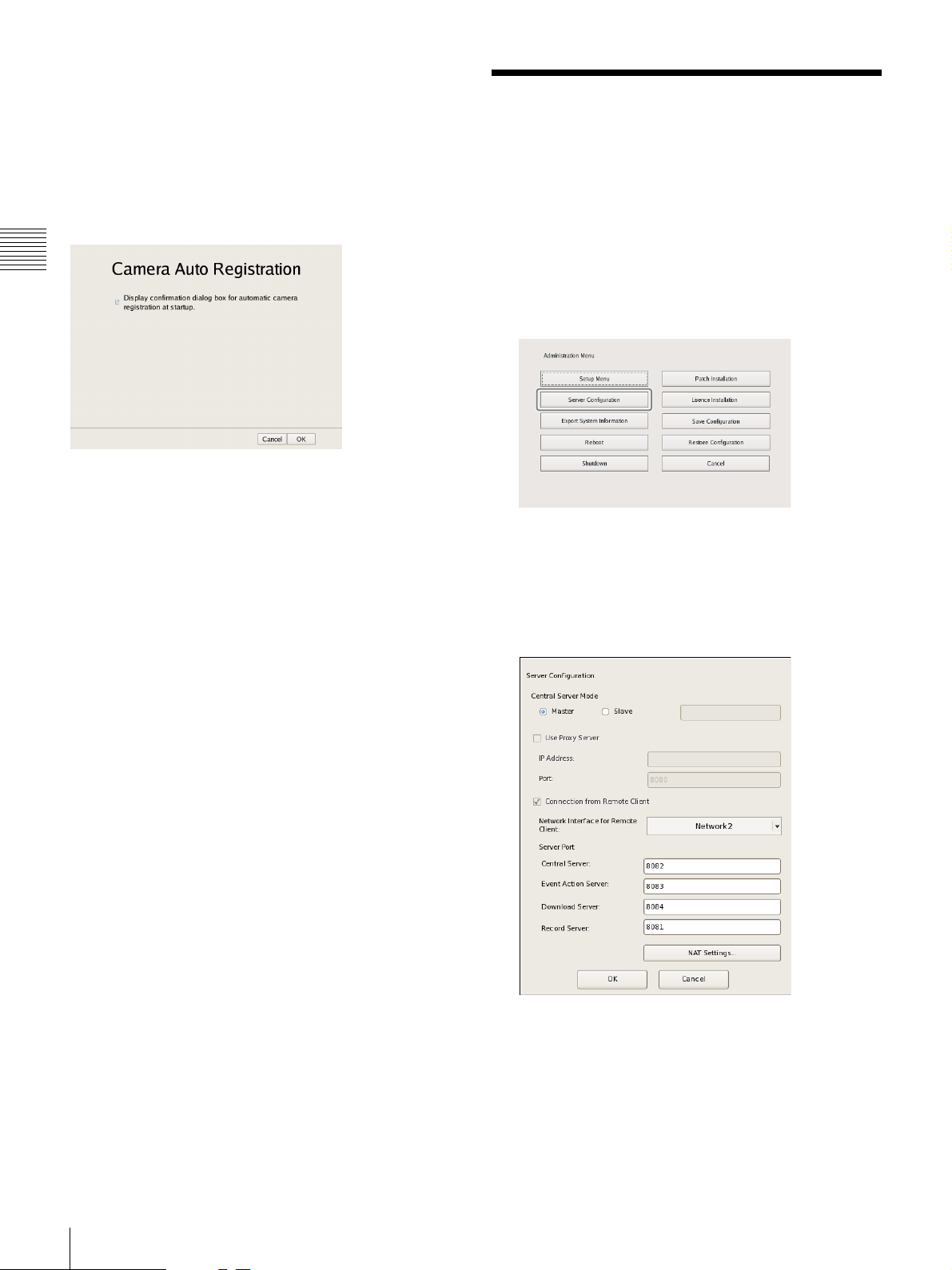
Setting Items of Camera Auto Registration
Screen
When you want to enable the camera auto registration
function, select the [Display confirmation dialog box for
automatic camera registration at startup] check box and
click [OK]. If you select this check box, the Camera
Automatic Registration screen appears when the unit starts
up.
Chapter 2
Administration Menu
Configuring Settings Related to Servers
Configure these settings when, for example, you want to
change the network settings to match the network
environment of the users, or you want to centralize user
administration when using multiple servers together.
1
Click [Server Configuration] in the Administration
Menu.
The menu items of the Administration Menu differ
depending on the server and clients.
The Server Configuration screen appears.
2
Configure each item, and click [OK].
Central Server Mode
Set this if you want to manage multiple servers as one
1)
system
Manager Advanced (Client).
, or you want to connect from RealShot
18
Configuring Settings Related to Servers
You can set one master server for uniformly managing
users in the system, and multiple slave servers.
1) This is for when you want to perform common user
management with multiple servers, or when you want to
connect from RealShot Manager Advanced (Client).
Select [Master] or [Slave].
If you select [Slave], enter the master server address to
which to connect.
If a server is changed from master to slave, the user
information that was configured locally is discarded
and the user information of the master is used.
If you want to change this setting, basically change it
immediately after installation.
If you change this setting, restart the system.
Use Proxy Server
Select the check box when using a proxy server for
connecting to the slave servers and master server of the
central server.
IP Address
Enter the IP address for the proxy server.
Port
Enter the port number for the proxy server.
Connection from Remote Client
Select the check box to connect from a remote client.
Network Interface for Remote Client
Select the network to use for the connecting with
remote client.
Server Port
Central Server
Configure the port number for the central server.
• When the central server mode or the server port is
changed, a message appears and the system restarts.
• If you changed the network interface for the remote
client, you must restart the system. When changing the
server mode, be sure to change the network interface
setting and restart the system beforehand.
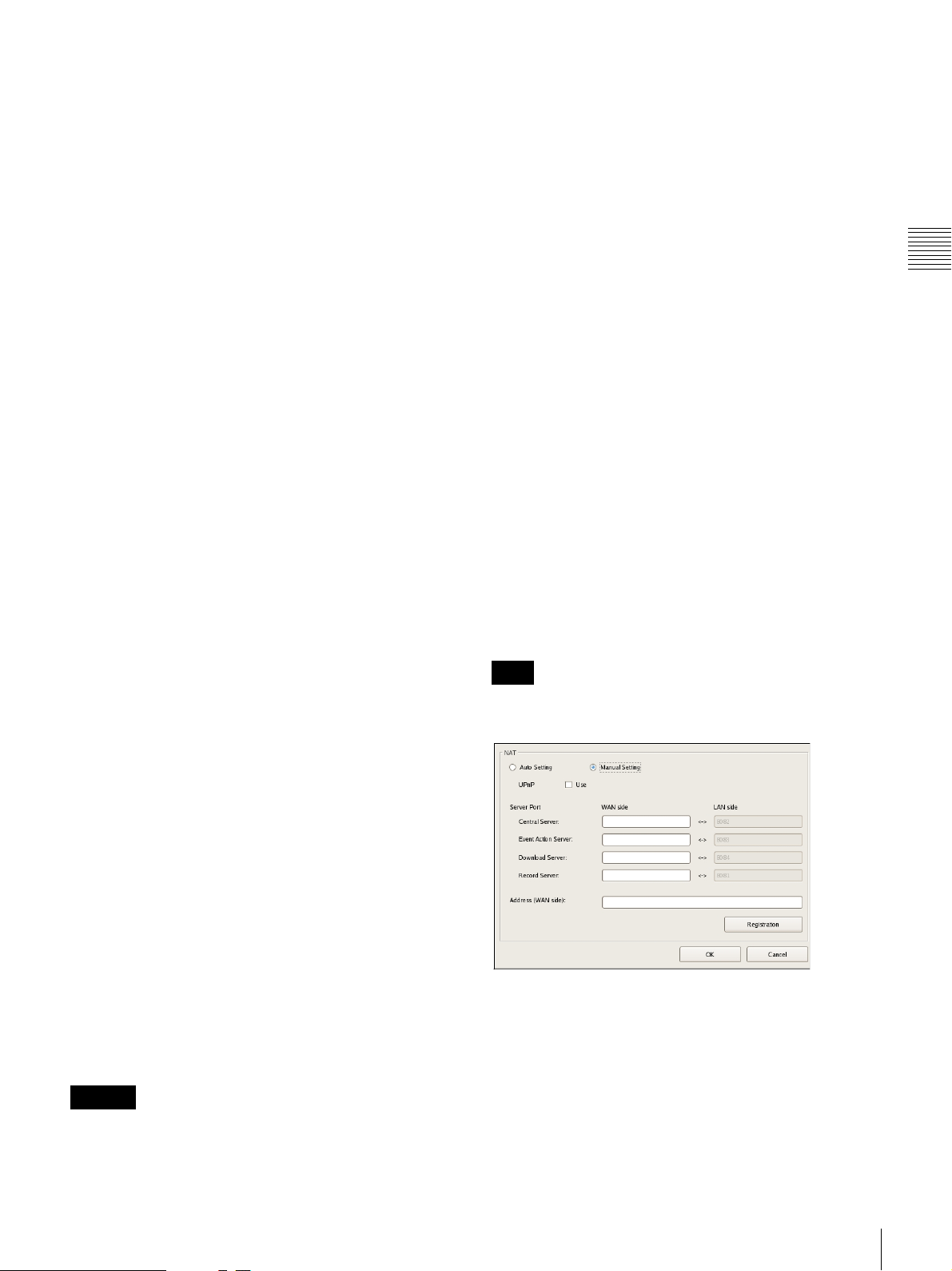
Setting Items of NAT Setting Dialog Box
Configure port forwarding settings for broadband routers.
If the router supports the UPnP function, you can use the
UPnP function to configure the router settings.
• If you select [Auto Setting], all of the setting items will
be configured automatically via UPnP. Select [Manual
Setting] if you want to specify port numbers manually.
• Regardless of whether [Auto Setting] or [Manual
Setting] is selected, router configuration is not necessary
if the UPnP function is used.
• If you select [Manual Setting] and do not use the UPnP
function, be sure to configure settings on the router side,
and enter those same settings for the appropriate items in
this dialog box.
• If you changed the network interface for the remote
client, you must restart the system. When changing the
server mode, be sure to change the network interface
setting and restart the system beforehand.
This dialog box appears when you select [NAT Settings]
on the Server Configuration screen (page 18). After
configuring each setting, click [OK].
Note
These settings are not required if you do not intend to
connect from clients on external networks.
Chapter 2
Administration Menu
Event Action Server
Configure the port number for the event action
server.
Download Server
Configure the port number for the download server.
Record Server
Configure the port number for the record server.
NAT Settings
Displays the NAT Setting dialog box (page 19).
Configure these settings when you want to connect
to the server via an Internet connection, for
example, from a client connected to an external
network using a broadband router.
Caution
• When changing to [Slave], register a user other than
“admin” on the master server, and use that user. The user
level for the user must be “Level 5”.
Auto Setting
Automatically configures settings for the router.
UPnP
If you select [Auto Setting], the [Use] check box will
be selected automatically.
Configuring Settings Related to Servers
19
Manual Setting
Specify port numbers and a global IP address.
When you select this option, enter values for each setting
item under [Server Port] and [Address (WAN side)].
Installing Patch Files
UPnP
To use the UPnP function, select the check box next to
[Use].
Server Port
Enter the WAN-side port number of the Central Server,
Chapter 2
Event Action Server, Download Server, and Record
Server.
The LAN-side port numbers are only for display and
cannot be configured.
Administration Menu
Address (WAN side)
Enter a global IP address.
Registration
Registers your settings.
Note
When connecting from a client, the [Address] and [Central
Server] under [Server Port] configured in the above will be
used as the client logon server.
Caution
• To ensure Internet (WAN side) security, be sure to use
the firewall function on your router or similar device,
and confirm that the security for the configured port is
enabled.
• If security is not enabled via the router or similar device,
there is a risk of the NSR being accessed by
unauthorized users via the WAN side ports. To improve
security, change the password regularly and configure
other related settings.
password, refer to “Changing the Password” (page 30).
• If unauthorized users log onto NSR, there is a risk of the
following.
– NSR settings may be changed.
– Images from cameras and recorded images may be
• Depending on your router and operating environment,
connection from an external network may be disabled.
1)
3)
viewed and operated.
2)
For details on changing the
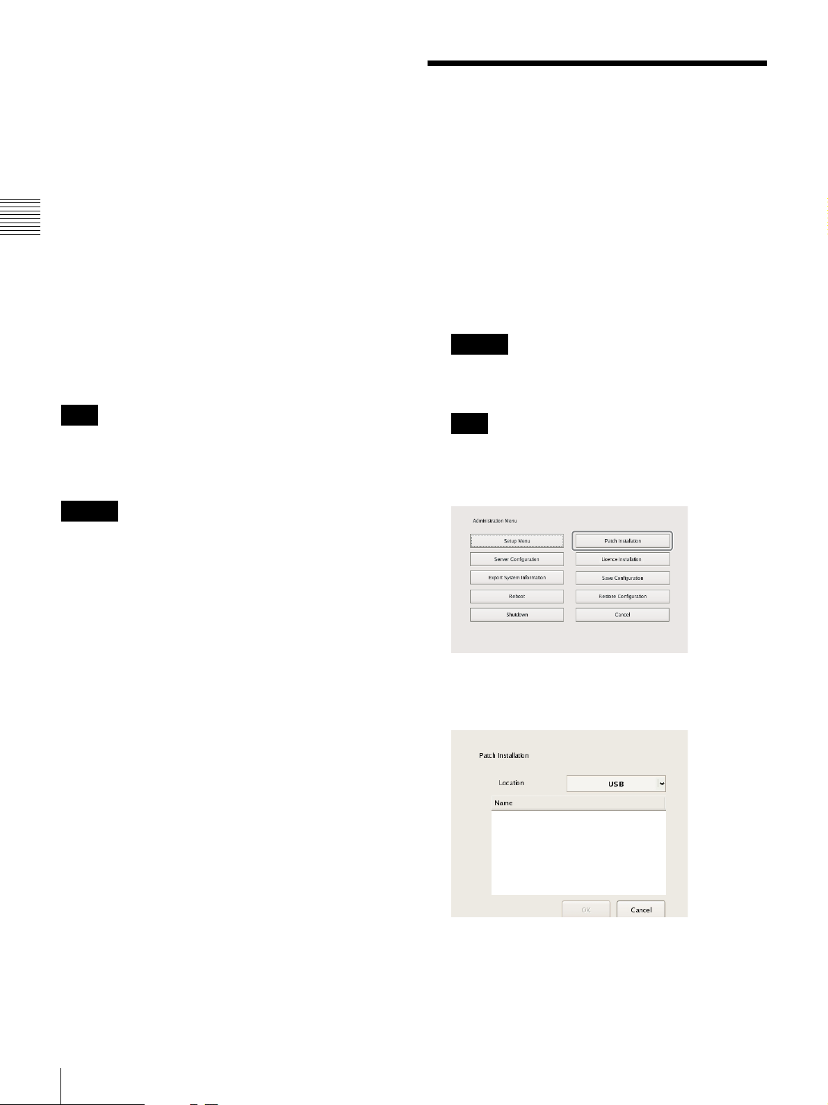
Patch files distributed by Sony can be installed on the
NSR.
A patch file is distributed when, for example, cameras
supported by the NSR are added to the lineup and when
new functions are added. We recommend installing patch
files so that you can operate the unit with the latest
software.
For details on patch file distribution, contact your Sony
dealer.
1
Copy the patch file onto a USB flash memory device.
Caution
Do not change the file name or other aspects of the
patch file.
Note
The USB flash memory only supports FAT32 format.
2
Click [Patch Installation] in the Administration Menu.
The Patch Installation screen appears.
3
Select the media on which the patch file is stored.
1) For details on router security settings, refer to the operating
instructions for the routers, or contact the manufacturer of
each router.
2) Changing the password does not guarantee prevention of log
on by unauthorized users.
3) Sony Corporation is not liable for any loss of profits incurred
by the customer as a result of such occurrences. The customer
is responsible for configuring appropriate settings and
measures.
20
Installing Patch Files
A list of patch file names appears.
4
Confirm a patch file name, and click [OK].
A confirmation message appears.
5
Confirm the content of the message, and click [Yes].
Caution
The NSR will automatically restart after installation of
certain patch files. A confirmation screen will appear
if restart is necessary. If you cannot stop your current
operations, select [No] to cancel installation, and
perform installation when restarting the NSR will not
be a problem.
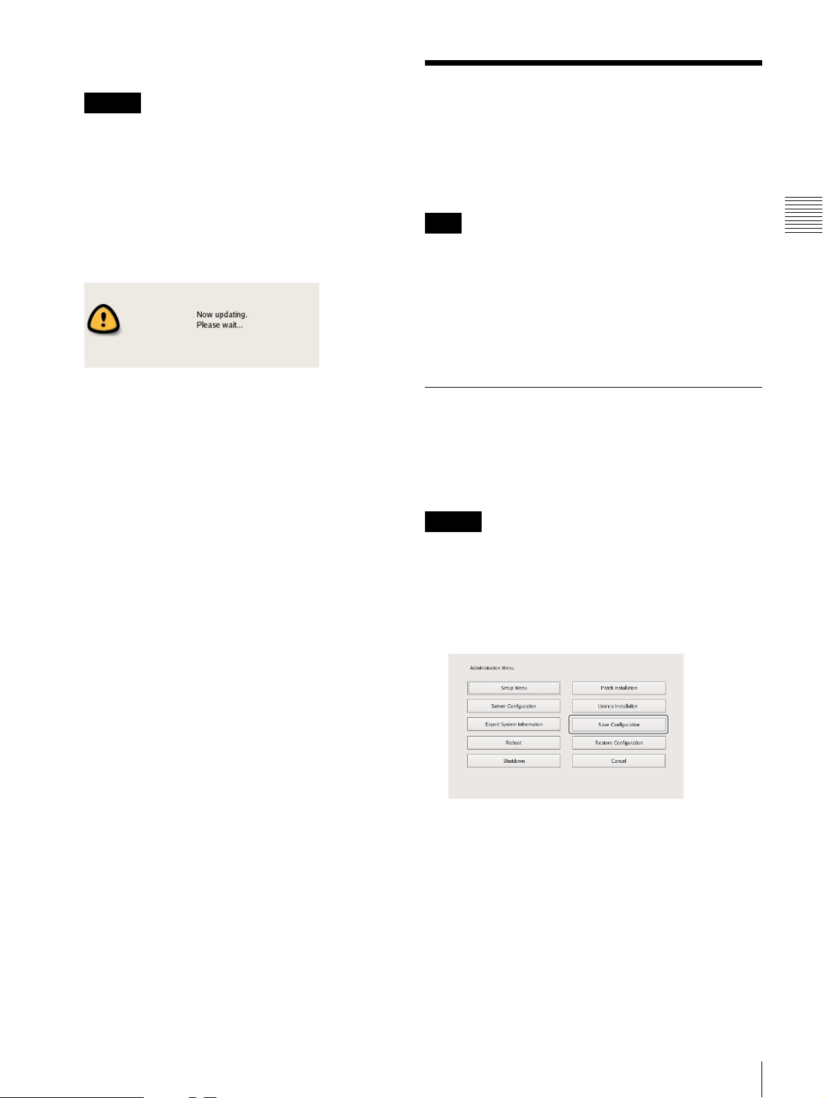
The following screen appears during installation of the
patch file.
When installation is complete, the patch is applied.
After restarting the unit, you can check the software
version under [Information] in the logon screen. Make
sure that the software has been updated to the correct
version.
Saving and Restoring Configuration Data
You can save the configuration data of NSR to external
media, and restore saved configuration data.
Note
Configuration data consists of configurations for all NSR
settings. You can quickly return to a previous
configuration environment by restoring configuration
data.
We recommend saving configuration data regularly each
time you change settings or upgrade the software version,
for example.
Saving Configuration Data
Generally, the settings configured in the Server
Configuration screen in the Administration Menu of the
logon screen and settings configured in the settings screen
after logging on are stored as configuration data.
Chapter 2
Administration Menu
Caution
Note that the following information is not saved.
• Recording records
• Log information
1
Click [Save Configuration] in the Administration
Menu.
The menu items of the Administration Menu differ
depending on the server and clients.
The Save Configuration screen appears.
Saving and Restoring Configuration Data
21
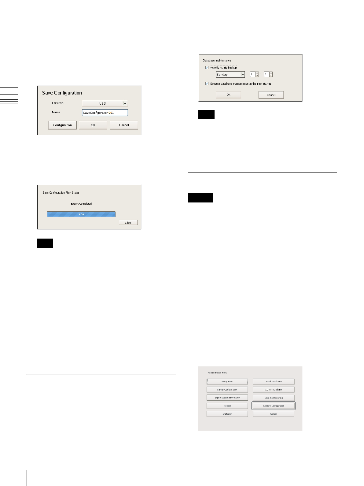
2
Select the media to save the configuration data, enter
the file name for the configuration data, and click
[OK].
You can use alphanumeric characters and some
symbols (periods (.), hyphens (-), underscores (_))
when entering the file name.
Chapter 2
2
Select the [Weekly / Daily backup] check box, specify
the day of the week and time to perform backup, and
then click [OK].
Note
Administration Menu
A progress bar is displayed during the backing up of
the configuration data, and the configuration data is
saved when the backup is finished.
3
Click [Close].
Note
When saving of the configuration data finishes, the
following files are created in the save location.
<Configuration data save name>.item
<Configuration data save name>_db.tar.gz
<Configuration data save name>_img.tar.gz
<Configuration data save name>_os.tar.gz
<Configuration data save name>_preset.tar.gz
Example: When the configuration data is saved under
the name “Configuration001,” files with the names
shown below are created.
Configuration001.item
Configuration001_db.tar.gz
Configuration001_img.tar.gz
Configuration001_os.tar.gz
Configuration001_preset.tar.gz
If you select the [Execute database maintenance at the
next startup] check box, the database will be backed up
and cleaned up at each startup. If a large volume of
recorded data is stored, this process may take several
minutes.
Restoring Configuration Data
Caution
• Note that the following information is not restored.
– Recording records
– System settings other than [Camera Auto Registration]
(Items of [Setup Menu] (page 13))
– Logs
• The settings of the external storage itself cannot be
restored, so it is necessary to configure them to the same
settings as those at the time of saving.
• The configuration data cannot be restored if the first two
digits of the current version (e.g.: “a.b” of “a.b.c”
separated by “.”) differ from those at the time of saving
or the model differs.
• When the configuration data is restored, the recording
operation performed up until that point is stopped
automatically. If a recording schedule has been
configured, recording resumes automatically after
restoration. If manual recording was performed, it needs
be started again.
1
Click [Restore Configuration] in the Administration
Menu.
Periodically Saving Configuration Data
You can periodically back up the database as a provision
for when the database is lost due to unforeseen problems.
1
Click [Configuration] in the Save Configuration
screen.
The Database maintenance screen appears.
22
Saving and Restoring Configuration Data
The menu items of the Administration Menu differ
depending on the server and clients.
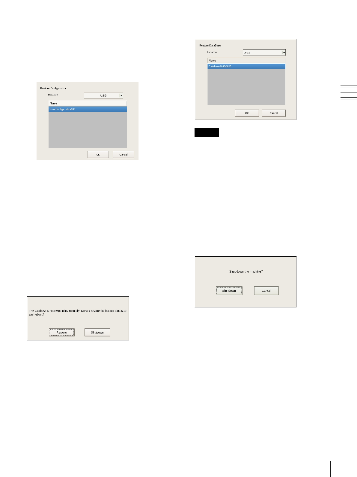
The Restore Configuration screen appears.
2
Select the location where the configuration data is
saved and the configuration data, and click [OK].
A confirmation message appears to notify you that this
operation will restart the unit.
3
Click [OK].
2
Click [OK].
Caution
When configuration data is restored via the above
message, the periodic backup data is restored. Be
aware that additions and changes to information
(including recording data) made after the backup
cannot be accessed.
The configuration data is restored.
Chapter 2
Administration Menu
A confirmation message appears.
4
Click [Yes].
A progress bar appears during restoring, NSR restarts
when the process is finished, and the configuration
data is restored.
If a problem occurs with the database
The following message appears. In such cases, the only
operations that can be performed are shutdown and data
restoration.
To restore configuration data
1
Click [Restore].
To skip configuration data restoration
1
Click [Shutdown].
A confirmation message appears.
2
Click [Shutdown].
The unit shuts down.
The following screen appears.
Saving and Restoring Configuration Data
23
Exporting System Information
You can save NSR system information as files onto
external media.
Note
Chapter 2
System information consists of NSR system configuration
information and logs.
Administration Menu
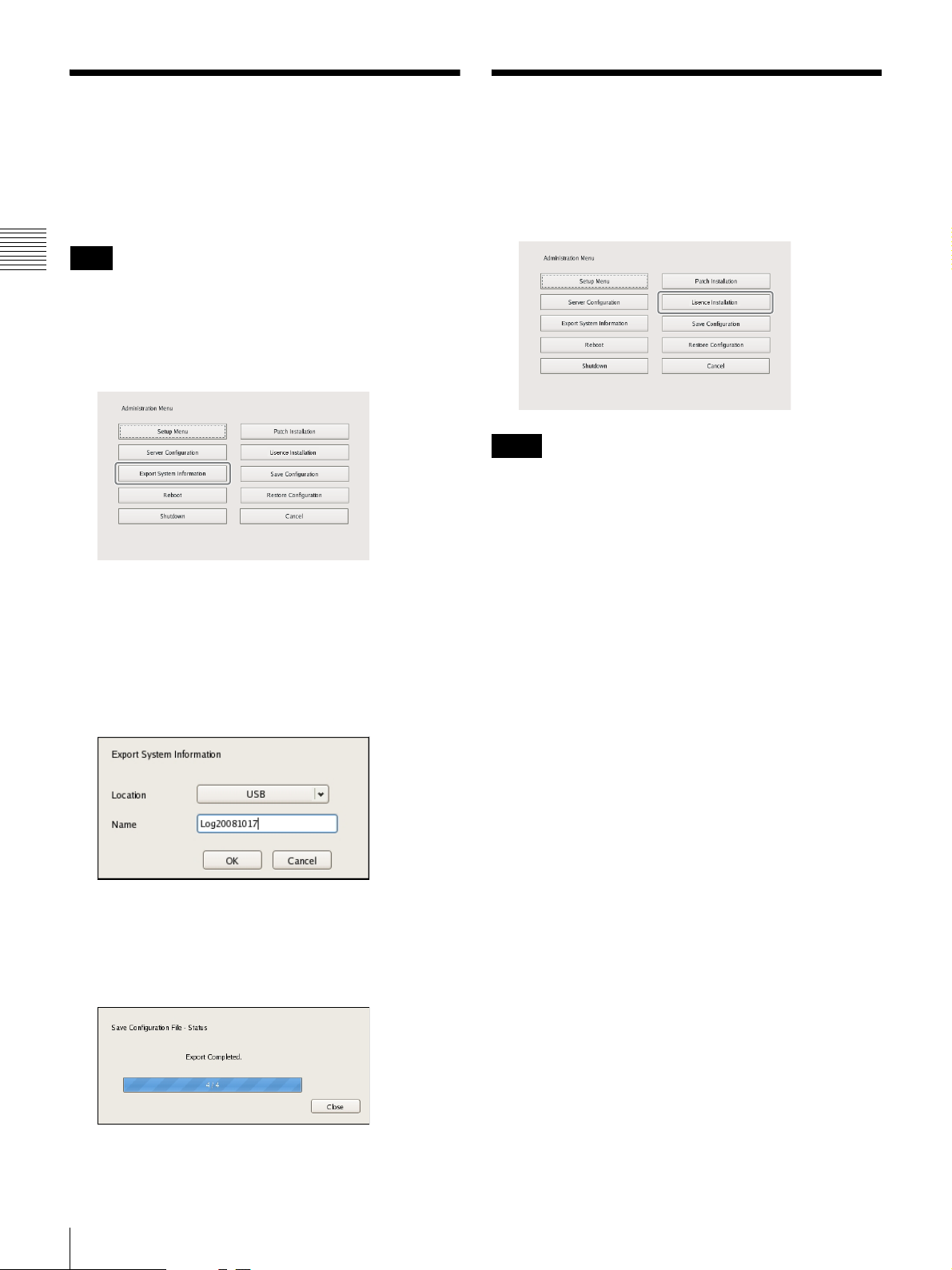
1
Click [Export System Information] in the
Administration Menu.
Installing Licenses
You can install a license on the NSR to enable registration
of additional cameras.
You can register up to 16 cameras normally, but this can
be increased to up to 24 cameras.
Notes
• For details on licenses, refer to the NSBK-CL05
Installation Guide (PDF).
• For details on acquiring licenses, contact your Sony
dealer.
The Export System Information screen appears.
2
Select the media on which to save the system
information, enter the file name, and then click [OK].
You can use alphanumeric characters and some
symbols (periods (.), hyphens (-), underscores (_))
when entering the file name.
A progress bar is displayed during exporting of the
system information, and the system information is
saved when exporting is finished.
3
Click [Close].
24
Exporting System Information / Installing Licenses

Basic Operation
Chapter
3
Overview
This chapter describes how to perform the following basic
operations on the NSR, including logging on, using
various windows, changing the password, and turning off
the unit.
• “Logging On to the NSR” (page 25)
• “Basic Window Operations” (page 27)
• “Changing the Password” (page 30)
• “Logging Off” (page 31)
• “Locking the NSR” (page 31)
• “Shutting Down and Restarting the NSR” (page 32)
• “Viewing Version Information” (page 32)
Note
For details on settings related to devices, schedules, sensor
inputs, and alarm outputs, see Chapter 4 “
Settings
for and playing back recorded images, see Chapter 5
“
” (page 33). For details on monitoring and search
Operation and Control
” (page 97).
Application
Logging On to the NSR
Before you can use the NSR, you must first log on.
1
Press the power switch on the front of the NSR to turn
it on.
The startup screen appears, and the progress bar for
software startup appears.
Note
The fan noise may be loud after turning on the unit.
This is not a malfunction.
Chapter 3 Basic Operation
After startup, the logon screen appears.
Overview / Logging On to the NSR
25

2
Enter the user name and password, and click [Logon].
Chapter 3 Basic Operation
• If you log on with the [Auto-Logon] check box
selected, the logon screen will not appear the next
time you start the application, and you will be logged
on automatically.
• To change the user that you are logged on as, first
log off from the Main screen.
• To enable the auto logon function, configure it from
the [Setup Menu] of the Administration Menu.
Caution
The selection status of the check box is applied each
time you log on.
Therefore, you must log on once in order for an
unselected status to be applied.
Note
The first time you turn on the NSR, the administrator
is the only user registered on the system. The default
user name for the administrator is as follows.
User name: admin
Password: admin
26
Logging On to the NSR
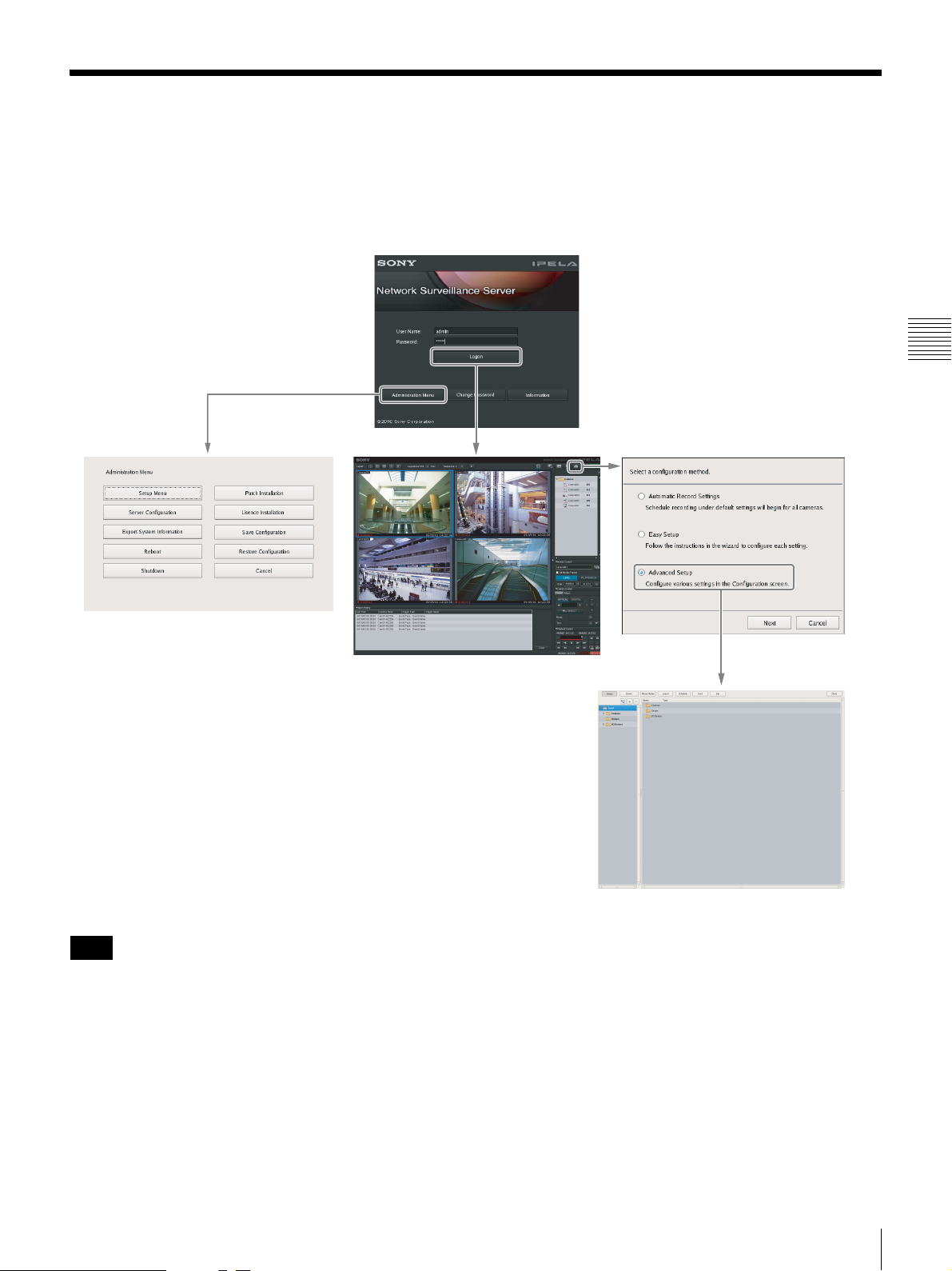
Basic Window Operations
This section provides a brief description of the basic operations for each screen.
The unit includes a Main screen for monitoring images, a configuration screen for configuring various settings, and an
Administration Menu for performing configurations and operations related to the NSR unit.
Logon Screen
Recorder Settings Screen
Chapter 3 Basic Operation
Administration Menu
Main Screen
Configuration Screen
Note
Click [Automatic Record Settings] or [Easy Setup] to register and configure cameras with a few simple operations. For
details on the operating procedures, refer to the Installation Manual (separate document).
Basic Window Operations
27
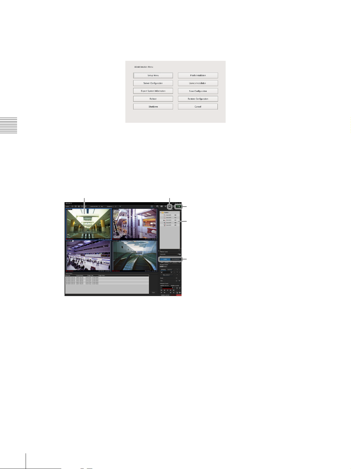
Administration Menu
When you click [Administration Menu] after entering your user name and password in the logon screen, the
Administration Menu screen appears. Click each button to configure settings and perform operations related to the NSR
unit.
Chapter 3 Basic Operation
For details on settings that can be configured from the Administration Menu, see Chapter 2 “
Administration Menu
(page 12).
Main screen
In the Main screen, you can monitor live images from each monitor frame, and search for and play back recorded images.
To switch between live image display and playback of recorded images, click the target monitor frame, and then click
[LIVE] or [PLAYBACK] on the right side of the window.
Monitor frame Displays the Configuration screen.
”
Allows you to log off or restart the NSR.
Select cameras.
Switch between live image display and
playback of recorded images.
For details on monitoring and searching for and playing back recorded images, see Chapter 5 “
(page 97).
Operation and Control
”
28
Basic Window Operations

Configuration screen
Configure settings that are necessary for operating the NSR, such as camera registration, schedule settings, and user
registration.
Click the button for the item you want to configure.
Returns to the Main screen.
Setting items appear based on the button you clicked.
Chapter 3 Basic Operation
For details on setting items and how to configure them, see Chapter 4 “
Application Settings
” (page 33).
Basic Window Operations
29
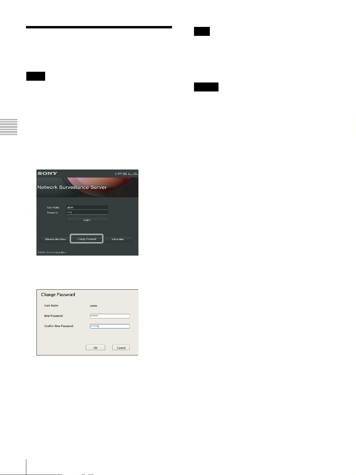
Changing the Password
You change the password for logging on to NSR.
Notes
Note
If [Enable Auto Logon] is enabled, the logon screen
will not appear during application startup, and you will
be logged on automatically. To change the password
while [Enable Auto Logon] is enabled, first log off
from the Main screen.
• The password is extremely important to the security of
this equipment. The first time you log in to NSR after
purchasing the equipment, be sure to change the
password before monitoring and configuring various
settings. Take care to keep the password secure.
• When using a System Controller (RM-NS1000) for
operations, create user names and passwords consisting
Chapter 3 Basic Operation
only of numbers.
1
Enter the user name and password on the Logon
screen, and click [Change Password].
Caution
When changing the password of an administrator or a
user with “User Configuration” permission, be sure to
memorize the new password.
The Change Password dialog box appears.
2
Enter a new password, and click [OK].
Enter the same password again in [Confirm New
Password].
The password is changed.
30
Changing the Password
Loading...