


SED2 VFD
SED2 VFD Electronic Bypass Options
Operating Instructions
Item Number 125-3208, Rev. FA


SED2 VFD Electronic
Bypass Option
Operating Instructions


NOTICE
The information contained within this document is subject to change without notice and should not be
construed as a commitment by Siemens Building Technologies, Inc. Siemens Building Technologies, Inc.
assumes no responsibility for any errors that may appear in this document.
All software described in this document is furnished under a license and may be used or copie d only in
accordance with the terms of such license.
WARNING
The Siemens Building Technologies SED2 Variable Frequency Drives are shipped w ithout EMC line filters.
(The EMC filter is most commonly used in Europe.) Where local codes or customer/installation requirements
dictate, separately orderable Class A line filters are available. More stringent Class B line filters are also
available for most models. Installation of these filters satisfies the requirements for the EU's EMC directive.
SERVICE STATEMENT
Control devices are combined to make a system. Each control device is mechanical in nature and all
mechanical components must be regularly serviced to optimize their operation. All Siemens Building
Technologies, Inc. branch offices and authorized distributors offer Technical Support Programs that will
ensure your continuous, trouble-free system performance.
For further information, contact your nearest Siemens Building Technologies, Inc. representative.
CREDITS
Product or company names mentioned herein may be the trademarks of their respective owners.
Copyright © 2007 by Siemens Building Technologies, Inc.
TO THE READER
Your feedback is important to us. If you have comments about this manual, please submit them to
SBT_technical.editor@siemens.com
Country of Origin: US


Table of Contents
How to Use this Manual................................................................................................ 1
Manual Organization.................................................................................................. 1
Manual Notations....................................................................................................... 1
Where To Send Comments ....................................................................................... 2
Reference Documents ............................................................................................... 2
Safety Instructions........................................................................................................ 3
Electronic Bypass Option Overview........................................................................... 4
General Description ................................................................................................... 4
Controller Board......................................................................................................... 5
Contactors.................................................................................................................. 6
Table of Contents
Keypad Functions ...................................................................................................... 6
Installation Instructions ............................................................................................... 9
Environmental Conditions.......................................................................................... 9
Mechanical Installation .............................................................................................. 9
Inspection ................................................................................................................ 9
Dimensions and Weights ........................................................................................ 9
Mounting.................................................................................................................. 10
Electrical Installation .................................................................................................. 12
Startup Procedures....................................................................................................... 19
Safety Precautions..................................................................................................... 19
Installation Inspection ................................................................................................ 19
Power-On................................................................................................................... 19
Quick Commissioning ................................................................................................ 21
Additional Parameter Settings ................................................................................... 31
Flying Start .............................................................................................................. 31
Automatic Restart.................................................................................................... 33
Vdc Controller.......................................................................................................... 36
Pulse Frequency ..................................................................................................... 37
Motor Data Identification ......................................................................................... 38
Reset to Factory Defaults........................................................................................ 40
Required SED2 Parameter Settings............................................................................ 41
Siemens Building Technologies, Inc. i

SED2 VFD Electronic Bypass Option Operating Instructions
Application Feature Setup ........................................................................................... 42
Overview .................................................................................................................... 42
Auto Bypass without Interlock.................................................................................... 42
Description .............................................................................................................. 42
Settings ................................................................................................................... 43
Example SED2 Settings.......................................................................................... 43
Interlock ..................................................................................................................... 44
Description .............................................................................................................. 44
Settings ................................................................................................................... 44
Wiring Example for Interlock ................................................................................... 46
Essential Services...................................................................................................... 46
Description .............................................................................................................. 46
Settings ................................................................................................................... 47
Wiring Example for Essential Services ................................................................... 47
Interlock and Auto Bypass on VFD Fault................................................................... 48
Description .............................................................................................................. 48
Settings ................................................................................................................... 48
Wiring Example for Interlock and Auto Bypass on VFD Fault ................................ 48
Technical Specifications.............................................................................................. 49
Troubleshooting............................................................................................................ 51
Power-on Initialization Failure (Unit Fault Condition) ............................................... 51
Override Jumper ........................................................................................................ 52
Fuses ......................................................................................................................... 52
ii Siemens Building Technologies, Inc.
How to Use this Manual
Manual Organization
This manual contains the following sections:
• How to Use this Manual, describes the organization of this manual and the
symbols used throughout this manual.
• Safety Instructions, provides general guidelines for your safety and to
prevent equipment damage.
• Electronic Bypass Option Overview, describes the Electronic Bypass Option
Controller board, inputs, outputs, contactors, and keypad.
How to Use this Manual
• Installation Instructions, provides mounting information and details on
electrical connections.
• Startup Procedures, provides step-by-step procedures to start up the
Electronic Bypass Option.
• Required SED2 Parameter Settings, lists SED2 parameter settings
necessary for operation of the Electronic Bypass Option.
• Application Feature Setup, describes application features and provides the
necessary parameter settings.
• Technical Specifications, lists Electronic Bypass Option and SED2 VFD
specifications.
• Troubleshooting, provides guidelines for troubleshooting the Electronic
Bypass Option.
Manual Notations
Notation Symbol Meaning
WARNING:
Indicates that personal injury/loss of life may occur if you do
not perform a procedure as specified.
CAUTION:
NOTES:
Siemens Building Technologies, Inc. 1
(no symbol) Provides other important information or helpful hints.
Indicates that equipment damage, or loss of data may occur if
you do not perform a procedure as specified.

SED2 VFD Electronic Bypass Option Operating Instructions
Where To Send Comments
Your feedback is important to us. If you have comments about this manual, please
submit them to technical.editor@sbt.siemens.com
Reference Documents
The following SED2 documentation is available from your local Siemens Building
Technologies, Inc. representative:
• SED2 VFD Startup Operation, and Maintenance Manual (125-3201),
provides operating instructions and procedures for the SED2.
• SED2 VFD Parameter Reference Guide (125-3214), provides descriptions of
SED2 parameters.
• SED2 VFD Submittal Sheet (154-042), provides a synopsis of the SED2
product line, accessories, and technical data.
.
• SED2 VFD Electronic Bypass Options Submittal Sheet (154-051), provides a
comprehensive overview of the SED2 Electronic Bypass option.
2 Siemens Building Technologies, Inc.

Safety Instructions
The following guidelines are provided for your safety, to prevent damage, and to
extend the service life of the SED2 product and any connected equipment. Read this
information carefully. Specific Warnings, Cautions, and Notes are provided in the
relevant sections of this manual.
WARNING:
• The SED2 uses hazardous voltages and controls potentially dangerous
rotating mechanical parts. Non-compliance with warnings or failure to follow
the instructions contained in this manual can result in loss of life, severe
personal injury, or serious damage to property/equipment.
• Only authorized personnel should work on this equipment, and only after
becoming familiar with all local regulations and ordinances; safety notices;
and installation, operation, and maintenance procedures in this manual.
Successful and safe operation of this equipment depends upon its proper
handling, installation, operation, and maintenance.
Safety Instructions
• Before carrying out any installation and commissioning procedures, you
must read all safety instructions and warnings, including all warning labels
attached to the equipment. Make sure that the warning labels are kept in a
legible condition and ensure missing or damaged labels are replaced.
• Observe the regulations of Safety Code VBG 4.0 (in particular, “Permissible
Deviations when Working with Live Parts”) whenever measuring or testing is
performed on live equipment. Also, use suitable electronic tools.
• Only use this equipment for the purpose specified by the manufacturer.
Unauthorized modifications and the use of spare parts and accessories that
are not sold or recommended by the manufacturer of the equipment can
cause fires, electric shocks, and injuries.
• Prevent the general public from accessing or approaching this equipment.
NOTE: Keep these Operating Instructions near the equipment and available to all
users.
Siemens Building Technologies, Inc. 3
SED2 VFD Electronic Bypass Option Operating Instructions
Electronic Bypass Option Overview
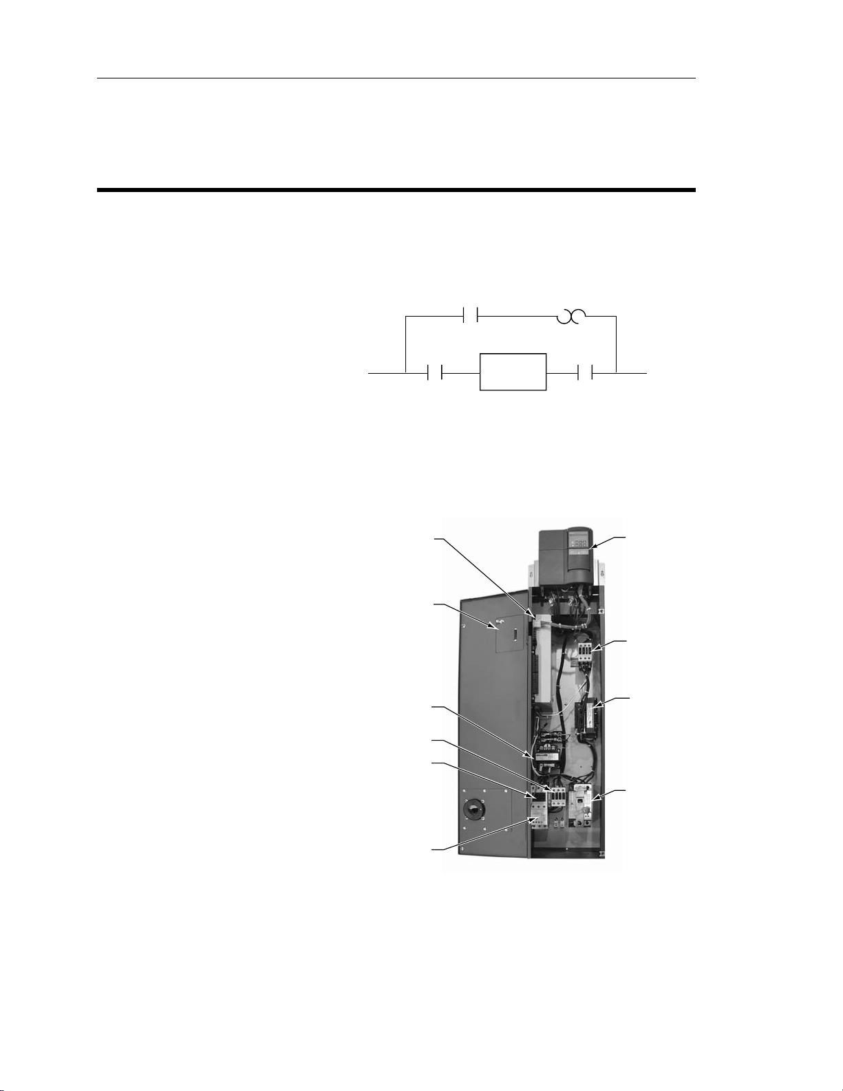
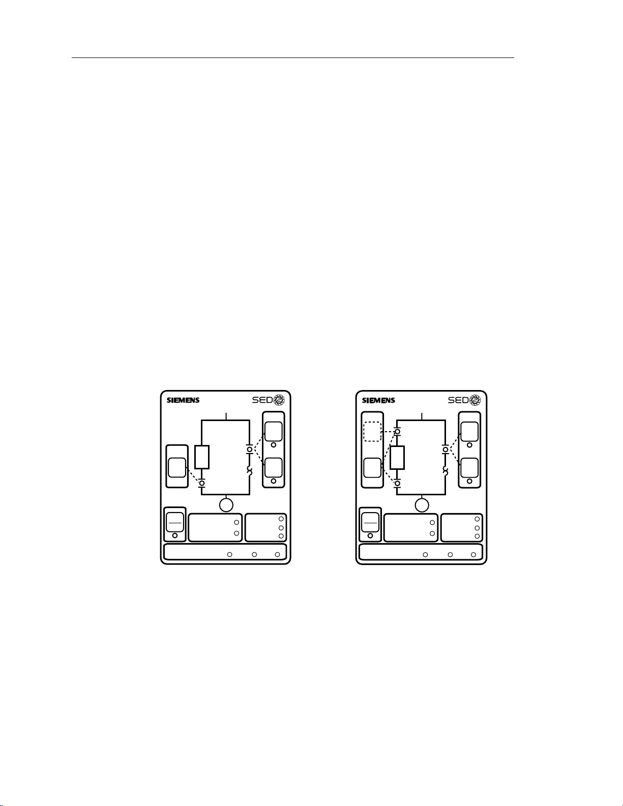
General Description
During normal operation in a typical
application, the input and output
contactors close and the SED2
operates the motor (Figure 1). The
bypass contactor provides the ability to
operate the motor on utility power and
eliminate the SED2 from the motor
control circuit. The SED2 Electronic
Bypass Option also allows you to select
features that enhance the control of the
contactors and the outputs that report
operation.
The SED2 Electronic Bypass
(E-Bypass) Option consists of a SED2
VFD, and a bypass enclosure with
electronic controls (Figure 2). The
electronic controls include:
• Controller board
• Keypad
• Step-down power transformer
• Contactors:
− Bypass
− Output
− Input (optional)
INPUT
CONTACTOR
VFD0093R1
Figure 1. Functional Block Diagram of
CONTROLLER
BOARD
KEYPAD
(DOOR
MOUNTED)
STEP-DOWN
POWER
TRANSFORMER
OUTPUT
CONTACTOR
BYPASS
CONTACTOR
BYPASS
CONTACTOR
OVERLOAD
RELAY
VFD
OUTPUT
CONTACTOR
Typical Electronic Bypass Option.
CONTACTOR
MOTOR
SED2 VFD
INPUT
REACTOR
(OPTIONAL)
• Overload (current) relay
• Reactor (optional)
• Disconnect switch (or optional
circuit breaker)
• Fuses (optional)
OVERLOAD
(CURRENT)
RELAY
VFD0094R1
Figure 2. Typical SED2 E-Bypass Components.
DISCONNECT
SWITCH
(OR OPTIONAL
CIRCUIT BREAKER
SHOWN)
• Cable harnesses
4 Siemens Building Technologies, Inc.
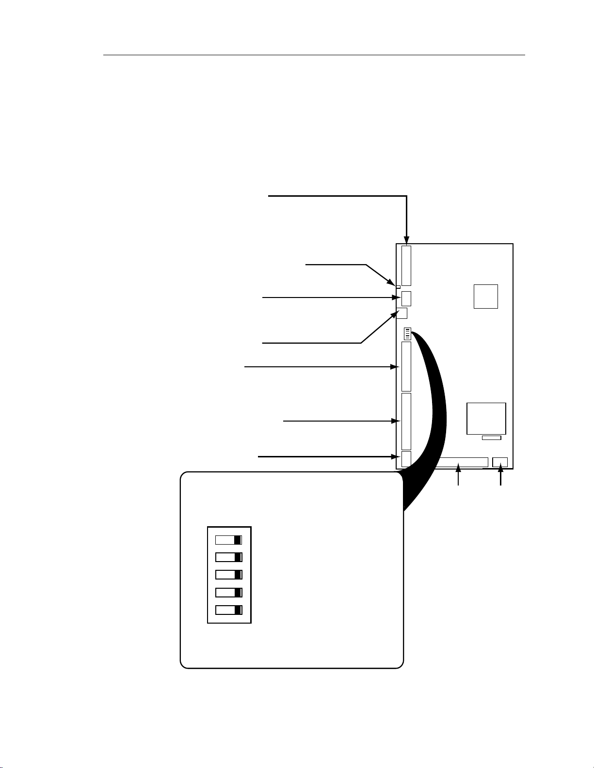
Controller Board
The Controller board is the foundation of the SED2 Electronic Bypass Option. It
controls communications to and from the SED2, keypad, isolated digital inputs,
relay/digital outputs, and contactors (Figure 3).
SED2 INTERFACE
Supports two SED2 non-isolated, digital relay
outputs and three SED2 digital inputs. The
maximum current draw for a relay output is 2 mA and
the voltage between the digital output source and return
lines is 24V. The Controller board provides unregulated,
non-isolated 24V to power the SED2 digital inputs.
BASIC SANITY TEST INDICATOR
Provides indication of initialization and
normal operation.
KEYPAD INTERFACE
Supports inputs and outputs from the Electronic
Bypass Option keypad. The keypad provides
user interface indicators and push buttons.
FACTORY USE ONLY
Connector J8 is for factory use only.
DIGITAL INPUTS
Supports six isolated digital inputs for customer use.
The inputs require a contact closure capable of
providing a low impedance path at currents less
than 20 mA.
DIGITAL RELAY OUTPUTS
Supports six digital relay outputs for customer use.
Each relay has a maximum rating of 2A at 120 Vac.
OVERRIDE JUMPER
Electronic Bypass Option Overview
J4
CONTROLLER
BOARD
SW1
J3
J8
ON
OFF
J2
J1
J6
MCU
TRANSFORMER
F1
J5J7
The Controller board DIP switches enable/disable
the Electronic Bypass Option features.
ON
5
OFF
Not used, factory test selector switch #2;
5
leave this switch OFF.
CONTACTOR
CONTROLS
POWER
Not used, factory test selector switch #1;
leave this switch OFF.
DIP SWITCHES
Interlock selector switch; requires
34
OPTIONS
34
SED2 programming.
Automatic Bypass selector switch;
requires SED2 programming.
12
ON
12
Essential Services selector switch.
SW1
When the switch is ON the option is enabled;
VFD0095R1
when the switch is OFF the option is disabled.
Figure 3. Controller Board Inputs and Outputs.
Siemens Building Technologies, Inc. 5
SED2 VFD Electronic Bypass Option Operating Instructions
Contactors
The Controller board provides two or three relay contact circuits controlled by the
Electronic Bypass Option: bypass, input, and output contactors. Each circuit includes
a NO relay. Controller board connector J7 enables circuit connections. The relay
circuits route power to the SED2 and the motor via the contactors. Controlling the
contactors through the relay circuits is the main function of the Controller board.
Bypass Contactor – The bypass relay on the Controller board controls the bypass
contactor. The output and bypass relays are interconnected to 120 Vac Hot. This
enables a safety circuit that prevents the bypass and output contactors from
simultaneously being energized.
Output Contactor – The output relay on the Controller board controls the output
contactor.
Input Contactor – The input relay on the Controller board controls the optional input
contactor.
Keypad Functions
Input
Contactor
Bypass
Contactor
VFD
Enable
STOP
Auto Bypass Enabled
RESET
INTERLOCK START LOGIC
VFD0096R1
2-CONTACTOR KEYPAD
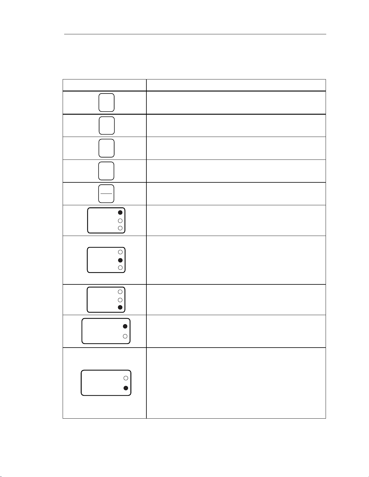
The keypad provides user interface indicators and pushbuttons. The following table
describes specific pushbutton and indicator functions:
Overload
Output
Contactor
Motor
Essential Services
Enable Commanded Proofed
Figure 4. E-Bypass Keypad Indicators and Pushbuttons.
Relay
Bypass
Hand
Start
Remote
VFD Fault
Safety Fault
Overload Fault
Start
VFD Bypass
Input
On/Off
Enable
STOP
RESET
INTERLOCK START LOGIC
VFD0097R1
Input
Contactor
VFD
Output
Contactor
Motor
Auto Bypass Enabled
Essential Services
Enable Commanded Proofed
Bypass
Contactor
Overload
Relay
Hand
Start
Remote
Start
VFD Fault
Safety Fault
Overload Fault
3-CONTACTOR KEYPAD
6 Siemens Building Technologies, Inc.
Electronic Bypass Option Overview
Pushbutton/Indicator Description
Input
On/Off
VFD0098R1
Enable
VFD0099R1
Hand
Start
VFD0100R1
Remote
Start
VFD0101R1
STOP
RESET
VFD0102R1
VFD Fault
Safety Fault
Overload Fault
VFD0103R1
VFD Fault
Safety Fault
Overload Fault
VFD0104R1
The Input On/Off pushbutton is supplied with the optional drive input
contactor. In VFD mode, this switch does nothing. In bypass mode, this
switch closes/opens the input contactor, switching the SED2 power on/off.
Enables SED2 operation by closing the input and output contactors.
Manually enables bypass mode operation by ensuring that the output
contactor is open and then closing the bypass contactor.
Activates the bypass mode and operates the bypass contactor according
to the status of the Remote Start input on the Controller board.
Opens the output and bypass contactors, disconnecting the motor.
When a VFD Fault is indicated, the VFD Fault indicator lights and the
VFD Fault Relay output on the Controller Board is triggered.
The Safety Fault indicator lights when either of the Remote Safety inputs
on the Controller board opens. The motor is prohibited from operating in
either the VFD or bypass modes while either of these contacts is open.
EXCEPTION: Essential Services ignores a Safety Fault.
NOTE: If not using the Remote Safety feature, hard wire the two
Remote Safety inputs.
VFD Fault
Safety Fault
Overload Fault
VFD0105R1
If the Electronic Bypass Option current overload relay trips, the Overload
Fault indicator lights and the motor will not run in bypass mode.
When the Auto Bypass DIP switch is enabled, the Auto Bypass Enabled
Auto Bypass Enabled
Essential Services
VFD0106R1
indicator is on steady. Bypass operation is automatically initiated by the
SED2.
When Auto Bypass is active, the Auto Bypass Enabled indicator flashes.
When the Essential Services DIP switch is enabled, the Essential
Services indicator is on steady.
When the Essential Services input is open, normal operation is indicated
Auto Bypass Enabled
Essential Services
VFD0107R1
as the output contactor remains closed to keep the motor running and the
Essential Services indicator is on steady.
When the Essential Services input is closed, the bypass contactor closes
and the Essential Services indicator flashes.
Nothing can interrupt the Essential Services mode except for the
Essential Services input opening.
Siemens Building Technologies, Inc. 7
SED2 VFD Electronic Bypass Option Operating Instructions
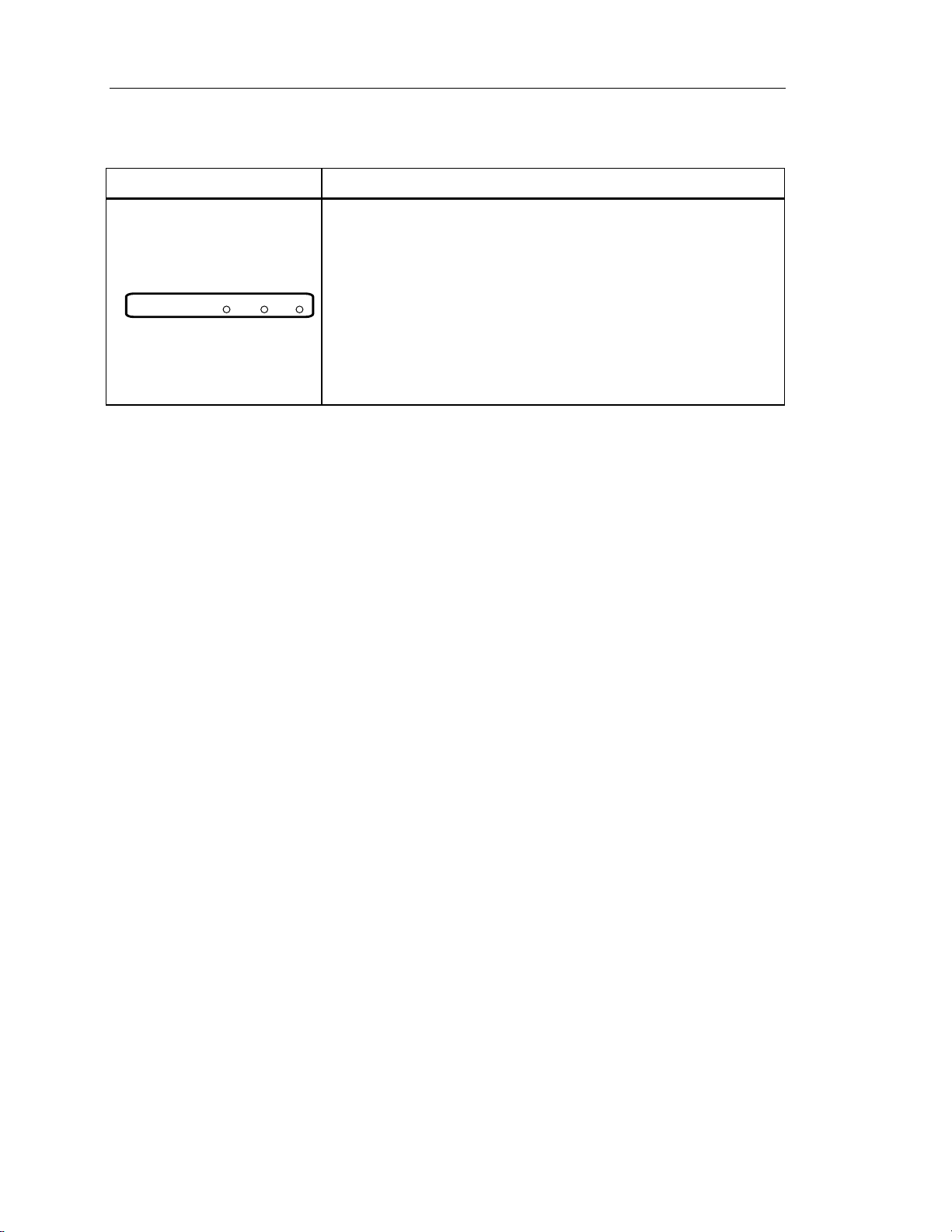
Pushbutton/Indicator Description
When the Interlock DIP switch is enabled, the Interlock Start Logic Enable
indicator is on steady. Any call to start the motor in either VFD or bypass
modes will not start the motor; instead it will close the Programmable
Output relay on the Controller board.
The Programmable Output can be used to actuate another device. When
this occurs, the Interlock Start Logic Commanded indicator also lights,
and the Interlock Start Logic Proofed indicator flashes.
A contact closure from this other device is wired to the Interlock Start on
the Controller board which then starts the motor and turns the Interlock
Start Logic Proofed indicator on steady. This feature is also called
damper end switch relay logic.
INTERLOCK START LOGIC
VFD0108R1
Enable Commanded Proofed
8 Siemens Building Technologies, Inc.

Installation Instructions
Environmental Conditions
Install the Electronic Bypass Option in a heated, indoor controlled environment that is free of
moisture and conductive contaminants such as condensation and dust. The air entering the
unit for ventilation/cooling must be clean and free from corrosive gases.
The ambient temperature must be between 14°F and 104°F (-10°C to 40°C) and the relative
humidity must be 0% to 95% noncondensing. Do not mount unit in direct sunlight.
Mechanical Installation
Installation Instructions
Inspection
1. As you unpack the Electronic Bypass Option, check for shipping damage. In the event of
damage, contact the transport company.
2. Locate the Electronic Bypass Option nameplate and confirm that the unit is configured to
the installation requirements.
3. Verify the delivery is complete. If not, contact the supplier.
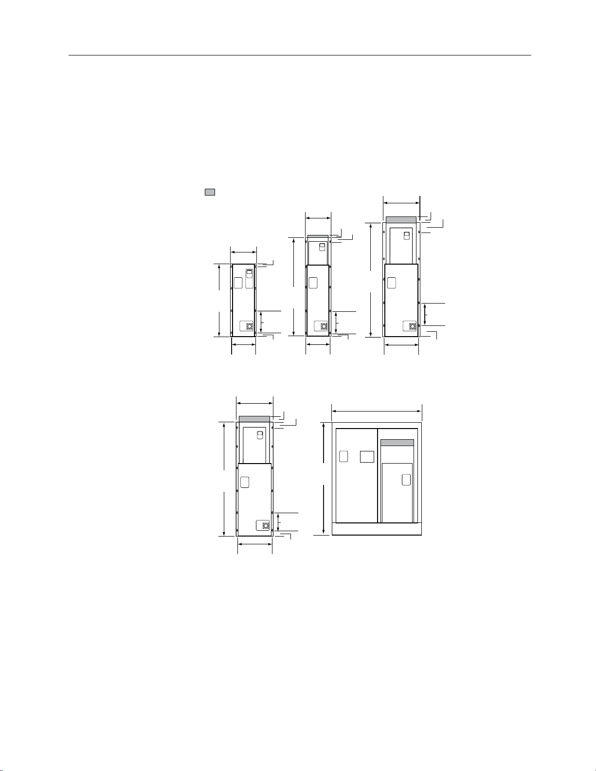
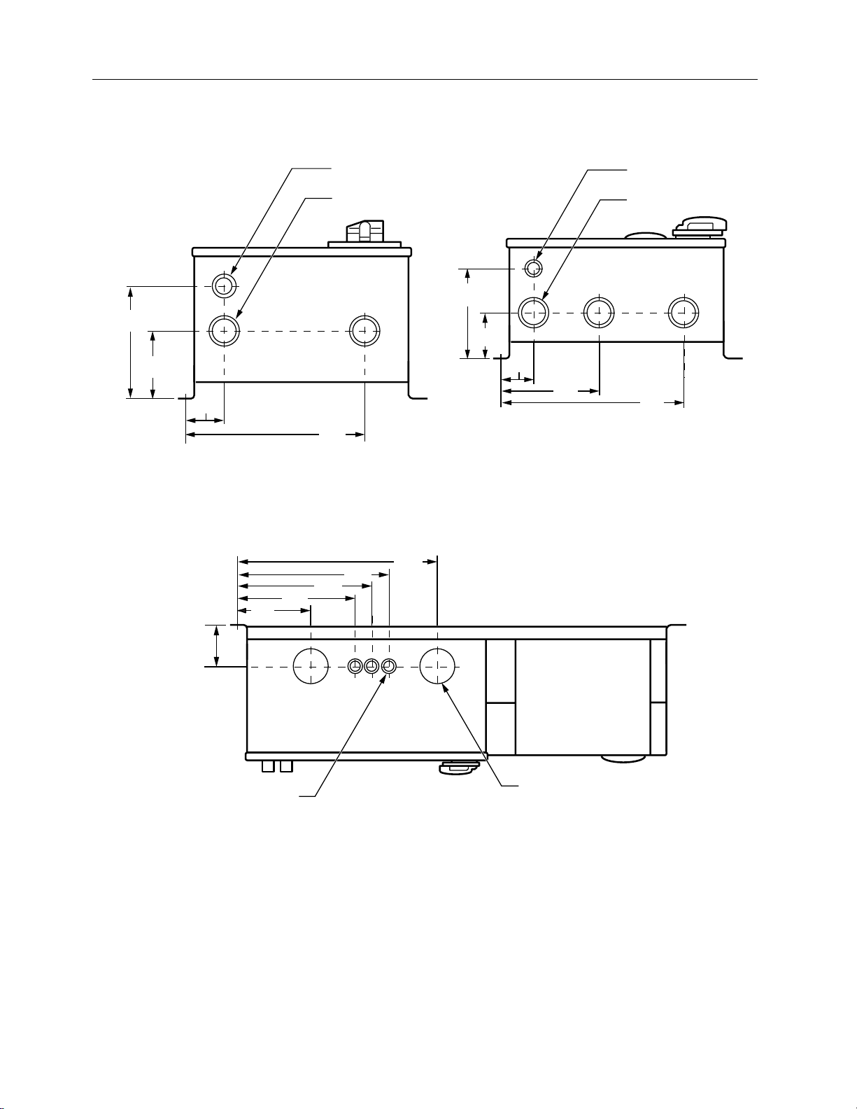
Dimensions and Weights
Figure 5 shows overall and mounting dimensions for the Electronic Bypass Option. Figures 6
through 8 show conduit locations.
Approximate weights are as follows.
Bypass
Frame Size
A 45 (20)
B 55 (25)
C 75 (34)
D 150 (68)
E 180 (82)
F 470 (213)
Weight lb (kg)
NOTE: Exact weight will be affected by actual horsepower/voltage and selected power
options.
Siemens Building Technologies, Inc. 9
SED2 VFD Electronic Bypass Option Operating Instructions
Mounting
1. To ensure safe installation, verify that the surface of the mounting location is level.
2. Mount the Electronic Bypass Option vertically with the SED2 operator panel, Electronic
Bypass Option keypad, and disconnect accessible.
= Protective Shield
Depth
With
Handle
9.6 (24)
13.2
(34)
34
(86)
12.4
(31)
Frame Size
A and B
Depth
With
Handle
12.2 (31)
58.5
(149)
20.8
(53)
Depth
Handle
9.6 (24)
1.5
(3.8)
10.5 TYP
(27)
1.5
(3.8)
2.9
(7.4)
With
(122)
48
3
(7.6)
11.5
(29)
10.6
(27)
Frame
Size C
57.5
(146)
1
(2.5)
11 TYP
2
(5)
(28)
2
(5)
Depth
With
Handle
10.4 (26)
53.5
(136)
45.5
(116)
20.8
(53)
19.9
(51)
Frame
Size D
2.9
(7.4)
(10)
11.5 TYP
(29)
3.4
(8.6)
Depth
17.4
(44)
4
10 TYP
(25)
19.9
(51)
VFD0127R2
5.5
(14)
Frame Size FFrame Size E
NOTE: It is recommended to leave 6 inches (15 cm) around the top and sides of the unit.
Figure 5. E-Bypass Dimensions in Inches (Centimeters).
10 Siemens Building Technologies, Inc.
Installation Instructions
S
S
6
(15.2)
3-5/8
(9.2)
2-1/8
(5.3)
VFD0201R1
Figure 6. Frame Sizes A through C Conduit
Locations. Viewed from Bottom;
Dimensions in Inches (Centimeters).
11-7/8
(30.1)
7-3/8
(18.7)
1/2 (1.3) AND 3/4 (1.9)
CONDUIT KNOCKOUT
3/4 (1.9) AND 1 (2.5)
CONDUIT KNOCKOUT
9-1/2
(24.1)
15-3/8
(39.1)
13-5/8
(34.6)
20-3/8
(51.7)
1/2 (1.3) AND 3/4 (1.9)
CONDUIT KNOCKOUTS
1-1/4 (3.2) AND 1-1/2 (3.8)
CONDUIT KNOCKOUTS (3)
8
(20.3)
4
(10.2)
2-3/4
(6.9)
8-1/2
(21.7)
VFD0202R1
16
(40.7)
Figure 7. Frame Sizes D and E Conduit Locations.
Viewed from Bottom;
Dimensions in Inches (Centimeters).
4-1/4
(10.8)
3/4 (1.9) AND 1 (2.5)
CONDUIT KNOCKOUTS (3)
VFD0203R1
3 (7.6) CONDUIT
KNOCKOUTS (2)
Figure 8. Frame Size F Conduit Locations. Viewed from Top; Dimensions in Inches (Centimeters).
Siemens Building Technologies, Inc. 11

SED2 VFD Electronic Bypass Option Operating Instructions
Electrical Installation
See Figure 9 for all Electronic Bypass Option wiring.
1. Route shielded twisted pair (recommended wire type) cable, 24 gauge minimum control
wiring in conduit through knockout and into housing (Figures 10 through 12). Connect
control wiring per job-specific drawings.
NOTES:
• Terminate shield at control device.
• Control wiring is 12 to 26 AWG and tightening torque is 5 lb-in.
2. If applicable, route communications wiring (P1) in conduit through knockout and into
housing (Figures 10 through 12). Continue to route communications wiring to SED2 and
terminate per SED2 VFD Startup, Operation, and Maintenance Manual (125-3201).
3. Route motor wiring in conduit through knockout and into housing (Figures 10 through 12).
Connect motor wiring to motor overload and ground lug. See Tables 1 through 4 for wire
sizes and tightening torques.
4. Route input power wiring in conduit through knockout and into housing (Figures 10
through 12). Connect input power wiring to disconnect switch and ground lug or to circuit
breaker and ground lug. See Tables 1 through 4 for wire sizes and tightening torques.
12 Siemens Building Technologies, Inc.
 Loading...