


 Loading...
MODULARIS Litho Vario
SP
Installation and Start-up
System
MODULARIS Litho Vario
© Siemens AG 2003
The reproduction, transmission or use of this document or its contents is not permitted without express written authority. Offenders will be liable for damages. All rights, including rights created by patent grant or registration of a utility model or design, are reserved.
Print No.: SPL1-130.814.02.07.02 |
English |
Replaces: SPL1-130.814.02.06.02 |
Doc. Gen. Date: 02.05 |

2 |
Revision / Disclaimer |
Document revision level
The document corresponds to the version/revision level effective at the time of system delivery. Revisions to hardcopy documentation are not automatically distributed.
Please contact your local Siemens office to order current revision levels.
Disclaimer
The installation and service of equipment described herein is to be performed by qualified personnel who are employed by Siemens or one of its affiliates or who are otherwise authorized by Siemens or one of its affiliates to provide such services.
Assemblers and other persons who are not employed by or otherwise directly affiliated with or authorized by Siemens or one of its affiliates are directed to contact one of the local offices of Siemens or one of its affiliates before attempting installation or service procedures.
MODULARIS Litho Vario |
SPL1-130.814.02.07.02 |
Page 2 of 88 |
Siemens AG |
|
02.05 |
CS PS 24 |
Medical Solutions |

Table of Contents |
3 |
1 _______ General information______________________________________________ 5
Important start-up information . . . . . . . . . . . . . . . . . . . . . . . . . . . . . . . . . . . . . . . . . . . . . 5 Applicability and regulations for regional companies . . . . . . . . . . . . . . . . . . . . . . . . . 5
MODULARIS Vario overview . . . . . . . . . . . . . . . . . . . . . . . . . . . . . . . . . . . . . . . . . . . . . . 6 MODULARIS Vario . . . . . . . . . . . . . . . . . . . . . . . . . . . . . . . . . . . . . . . . . . . . . . . . . . . 6
Required technical documents . . . . . . . . . . . . . . . . . . . . . . . . . . . . . . . . . . . . . . . . . . . . . 7
Required tools and measurement devices . . . . . . . . . . . . . . . . . . . . . . . . . . . . . . . . . . . . 8 Required material . . . . . . . . . . . . . . . . . . . . . . . . . . . . . . . . . . . . . . . . . . . . . . . . . . . . 8
Protective measures. . . . . . . . . . . . . . . . . . . . . . . . . . . . . . . . . . . . . . . . . . . . . . . . . . . . . 9
2 _______ Installation ____________________________________________________ 10
Overview. . . . . . . . . . . . . . . . . . . . . . . . . . . . . . . . . . . . . . . . . . . . . . . . . . . . . . . . . . . . . 10 SIREMOBIL and monitor trolley . . . . . . . . . . . . . . . . . . . . . . . . . . . . . . . . . . . . . . . . 10 MODULARIS Uro Plus . . . . . . . . . . . . . . . . . . . . . . . . . . . . . . . . . . . . . . . . . . . . . . . 10 SONOLINE . . . . . . . . . . . . . . . . . . . . . . . . . . . . . . . . . . . . . . . . . . . . . . . . . . . . . . . . 10 Unpacking LITHOSTAR MODULARIS Vario . . . . . . . . . . . . . . . . . . . . . . . . . . . . . . 10 Docking unit . . . . . . . . . . . . . . . . . . . . . . . . . . . . . . . . . . . . . . . . . . . . . . . . . . . . . . . 12 Combination with ARCADIS Orbic/SIREMOBIL . . . . . . . . . . . . . . . . . . . . . . . . . . . . 18 Unit association - labeling . . . . . . . . . . . . . . . . . . . . . . . . . . . . . . . . . . . . . . . . . . . . . 19 C-arm unit isocenter cross . . . . . . . . . . . . . . . . . . . . . . . . . . . . . . . . . . . . . . . . . . . . 20 External isocenter cross manufacturer . . . . . . . . . . . . . . . . . . . . . . . . . . . . . . . . . . . 21 Radiation release option . . . . . . . . . . . . . . . . . . . . . . . . . . . . . . . . . . . . . . . . . . . . . . 22 MODULARIS Uro Table . . . . . . . . . . . . . . . . . . . . . . . . . . . . . . . . . . . . . . . . . . . . . . 22 ECG triggering option . . . . . . . . . . . . . . . . . . . . . . . . . . . . . . . . . . . . . . . . . . . . . . . . 25
3 _______ Start-up _______________________________________________________ 28
C-arm unit and monitor trolley . . . . . . . . . . . . . . . . . . . . . . . . . . . . . . . . . . . . . . . . . . . . 28
LITHOSTAR MODULARIS . . . . . . . . . . . . . . . . . . . . . . . . . . . . . . . . . . . . . . . . . . . . . . . 29 Checking the line voltage . . . . . . . . . . . . . . . . . . . . . . . . . . . . . . . . . . . . . . . . . . . . . 29 Installing the coupling pump . . . . . . . . . . . . . . . . . . . . . . . . . . . . . . . . . . . . . . . . . . . 30 Filling the cooling circuit . . . . . . . . . . . . . . . . . . . . . . . . . . . . . . . . . . . . . . . . . . . . . . 30 Filling the coupling circuit . . . . . . . . . . . . . . . . . . . . . . . . . . . . . . . . . . . . . . . . . . . . . 31 Checking the isocenter with X-ray . . . . . . . . . . . . . . . . . . . . . . . . . . . . . . . . . . . . . . 32 Triggering shock waves . . . . . . . . . . . . . . . . . . . . . . . . . . . . . . . . . . . . . . . . . . . . . . 34 Triggering shock waves with ECG (optional) . . . . . . . . . . . . . . . . . . . . . . . . . . . . . . 35 Pressure measurement. . . . . . . . . . . . . . . . . . . . . . . . . . . . . . . . . . . . . . . . . . . . . . . 35
MODULARIS Uro (table) . . . . . . . . . . . . . . . . . . . . . . . . . . . . . . . . . . . . . . . . . . . . . . . . 36
Ultrasound localization (if present) . . . . . . . . . . . . . . . . . . . . . . . . . . . . . . . . . . . . . . . . . 37 SONOLINE G20 . . . . . . . . . . . . . . . . . . . . . . . . . . . . . . . . . . . . . . . . . . . . . . . . . . . . 38 SONOLINE Adara. . . . . . . . . . . . . . . . . . . . . . . . . . . . . . . . . . . . . . . . . . . . . . . . . . . 38 SONOLINE Prima . . . . . . . . . . . . . . . . . . . . . . . . . . . . . . . . . . . . . . . . . . . . . . . . . . . 38 Probes. . . . . . . . . . . . . . . . . . . . . . . . . . . . . . . . . . . . . . . . . . . . . . . . . . . . . . . . . . . . 39
Selecting the MODULARIS cross on the SONOLINE G20 . . . . . . . . . . . . . . . . . . . . . . 41 Ultrasound localization . . . . . . . . . . . . . . . . . . . . . . . . . . . . . . . . . . . . . . . . . . . . . . . 41
Selecting the MODULARIS cross on the SONOLINE Adara . . . . . . . . . . . . . . . . . . . . . 42 Ultrasound localization . . . . . . . . . . . . . . . . . . . . . . . . . . . . . . . . . . . . . . . . . . . . . . . 42
Siemens AG |
SPL1-130.814.02.07.02 |
Page 3 of 88 |
MODULARIS Litho Vario |
Medical Solutions |
02.05 |
CS PS 24 |
|

4 |
Table of Contents |
Selecting the MODULARIS cross on the SONOLINE Prima . . . . . . . . . . . . . . . . . . . . . 43
. . . . . . . . . . . . . . . . . . . . . . . . . . . . . . . . . . . . . . . . . . . . . . . . . . . . . . . . . . . . . . . . . . 43 Ultrasound localization . . . . . . . . . . . . . . . . . . . . . . . . . . . . . . . . . . . . . . . . . . . . . . . 43
Adhesive labels for ultrasound units . . . . . . . . . . . . . . . . . . . . . . . . . . . . . . . . . . . . . . . . 45
MUT MODULARIS . . . . . . . . . . . . . . . . . . . . . . . . . . . . . . . . . . . . . . . . . . . . . . . . . . . . . 46
Final work steps . . . . . . . . . . . . . . . . . . . . . . . . . . . . . . . . . . . . . . . . . . . . . . . . . . . . . . . 47
4 _______ Ultrasound localization retrofit____________________________________ 48
Cable mount on the support arm. . . . . . . . . . . . . . . . . . . . . . . . . . . . . . . . . . . . . . . . . . . 52
Cable holder on the cable . . . . . . . . . . . . . . . . . . . . . . . . . . . . . . . . . . . . . . . . . . . . . . . . 53
Ultrasound probes. . . . . . . . . . . . . . . . . . . . . . . . . . . . . . . . . . . . . . . . . . . . . . . . . . . . . . 54
Adhesive labels for ultrasound unit . . . . . . . . . . . . . . . . . . . . . . . . . . . . . . . . . . . . . . . . . 55
Adjustment and start-up . . . . . . . . . . . . . . . . . . . . . . . . . . . . . . . . . . . . . . . . . . . . . . . . . 56
LithoShare with several ultrasound units . . . . . . . . . . . . . . . . . . . . . . . . . . . . . . . . . . . . 57 SONOLINE G20 . . . . . . . . . . . . . . . . . . . . . . . . . . . . . . . . . . . . . . . . . . . . . . . . . . . . 57 SONOLINE Adara . . . . . . . . . . . . . . . . . . . . . . . . . . . . . . . . . . . . . . . . . . . . . . . . . . . 58 SONOLINE Prima . . . . . . . . . . . . . . . . . . . . . . . . . . . . . . . . . . . . . . . . . . . . . . . . . . . 59
5 _______ Isocenter with ultrasound ________________________________________ 60
Preparations . . . . . . . . . . . . . . . . . . . . . . . . . . . . . . . . . . . . . . . . . . . . . . . . . . . . . . . . . . 60 Checking the target on the SONOLINE G20 . . . . . . . . . . . . . . . . . . . . . . . . . . . . . . . 62 Checking image tilt . . . . . . . . . . . . . . . . . . . . . . . . . . . . . . . . . . . . . . . . . . . . . . . . . . 64 Checking the target on the Sonoline Adara. . . . . . . . . . . . . . . . . . . . . . . . . . . . . . . . 69 Checking image tilt . . . . . . . . . . . . . . . . . . . . . . . . . . . . . . . . . . . . . . . . . . . . . . . . . . 70 Checking the target on the Sonoline Prima . . . . . . . . . . . . . . . . . . . . . . . . . . . . . . . . 76 Checking image tilt . . . . . . . . . . . . . . . . . . . . . . . . . . . . . . . . . . . . . . . . . . . . . . . . . . 78
6 _______ Final work steps________________________________________________ 84
Customer and country-specific settings . . . . . . . . . . . . . . . . . . . . . . . . . . . . . . . . . . . . . 84 Setting the system clock (if necessary) . . . . . . . . . . . . . . . . . . . . . . . . . . . . . . . . . . . 84 Setting the user language (if necessary) . . . . . . . . . . . . . . . . . . . . . . . . . . . . . . . . . . 84
Backup and error memory. . . . . . . . . . . . . . . . . . . . . . . . . . . . . . . . . . . . . . . . . . . . . . . . 85
Remaining work . . . . . . . . . . . . . . . . . . . . . . . . . . . . . . . . . . . . . . . . . . . . . . . . . . . . . . . 86
7 _______ Changes to previous version _____________________________________ 87
MODULARIS Litho Vario |
SPL1-130.814.02.07.02 |
Page 4 of 88 |
Siemens AG |
|
02.05 |
CS PS 24 |
Medical Solutions |

General information |
5 |
Important start-up information
The device was installed, programmed, and tested at the factory (see the test certificate filed in the “technical documentation” system binder).
During start-up, you will only need to perform a few tests or measurements to ensure that none of the settings have changed.
All measurement results from measurements labeled with p must be entered in the test certificate listed in each instance.
NOTE |
|
These measurement values as well as the values determined dur- |
|
|
ing start-up can be copied from the test certificate to the accep- |
|
||
|
|
tance certificate. |
|
|
|
Applicability and regulations for regional companies
Equivalent leakage current measurement
The equivalent leakage current must be measured where applicable under the requirements of DIN VDE 0751 Part 1.
Where DIN VDE 0751 does not apply, the regional companies should comply with the following regulations (refer to ARTD - 002.731.17, Safety-related regulations for installation and maintenance).
The national regulations apply primarily for the regional companies.
In the event that there are no existing regulations, the following provisions should be adhered to in the interest of the safety of customers, patients, employees and third parties as well as the company.
Initial measured value
The equivalent leakage current measurement was performed at the factory and the value measured was entered in test protocol 1. The measurement was made at the line voltage and line frequency indicated in test protocol 1.
If the on-site line voltage or line frequency deviates from the information indicated upon delivery, the values given are invalid. The values should be marked invalid (crossed out with the comment “invalid values“ and this copy should be signed and dated).
The equivalent leakage current measurement must be repeated. According the DIN VDE 0751 Part 1, the resulting value may not exceed 1 mA.
The initial measured value must be documented.
Repeat measurements
When service or repair work is performed on the primary power supply circuit (e.g. repairs to the power-on circuit), the equivalent leakage current test must be repeated. The values measured in the subsequent test may not exceed the threshold value of 1 mA as specified in VDE 0751, Part 1. In addition, they may not exceed the initial measured value by more than 50%. If the value exceeds this threshold, the system must be repaired. The measured value must be documented.
Siemens AG |
SPL1-130.814.02.07.02 |
Page 5 of 88 |
MODULARIS Litho Vario |
Medical Solutions |
02.05 |
CS PS 24 |
|

6 |
General information |
MODULARIS Vario overview
MODULARIS Vario
Fig. 1: Vario
Pos. 1 Shock wave head C plus with 140 mm penetration depth with adapted isocenter phantom.
Pos. 2 Therapy arm incl. head 900 mm
Pos. 3 Energy charger with fast high voltage switch
Pos. 4 Docking system with docking mandrel
MODULARIS Litho Vario |
SPL1-130.814.02.07.02 |
Page 6 of 88 |
Siemens AG |
|
02.05 |
CS PS 24 |
Medical Solutions |

General information |
7 |
Required technical documents |
|
• Start-up, release for operation |
SPL1-130.815.01.. |
• * Dimension certificate from the PG |
SPL1-130.891.01.. |
• MODULARIS Vario service instructions |
SPL1-130.840.01.. |
• **C-arm unit installation instructions |
n.a. |
• **Monitor trolley installation instructions |
n.a. |
• **C-arm unit start-up instructions |
n.a. |
• **LITHOSTAR MODULARIS Vario adaptation |
SPR2-130.814.05.. |
• MODULARIS Uro Plus operating instructions |
SPL1-130.620.01.. |
• MODULARIS Vario operating instructions |
SPL1-130.620.05.. |
• C-arm unit operating instructions |
n.a. |
• Service instructions for shock wave pressure and po- |
SPL2-120.074.01 |
sition control |
|
* Only in combination with a non-Siemens C-arm unit. **Only in combination with Siemens C-arm units.
Siemens AG |
SPL1-130.814.02.07.02 |
Page 7 of 88 |
MODULARIS Litho Vario |
Medical Solutions |
02.05 |
CS PS 24 |
|

8 |
General information |
Required tools and measurement devices
•Standard installation tool kit
•Service PC, see intranet, service laptop for CSEs
• |
PC connection cable, 5m |
99 00 440 RE999 |
• |
Internal line resistance meter |
84 28.104 RE999 |
•ESD equipment
• |
Protective conductor tester |
44 15 899 |
RV090 |
• DVM, e.g.. Fluke 187 |
99 94 831 |
|
|
• |
Pressure test device |
30 95 408 |
J1008 |
• Adapter for C-head |
98 17 347 |
J1008 |
|
• |
Bender safety tester |
97 06 979 |
Y0526 |
• Spray can or varnish applicator of the color white grained |
99 00 705 |
RE999 |
|
|
MED surface no. 4146 similar to RAL grayish white 9002. |
|
|
Required material
•Approx. 5 liters of sterile water
MODULARIS Litho Vario |
SPL1-130.814.02.07.02 |
Page 8 of 88 |
Siemens AG |
|
02.05 |
CS PS 24 |
Medical Solutions |

General information |
9 |
Protective measures
•Adhere to the protective measures described in register 1 of the system binder.
•When performing the work steps, the product-specific safety information contained in the document as well as the general safety information in ARTD, Part 2 must be observed.
•Observe ESD guidelines!

 WARNING Dangerous X-ray radiation and/or dangerous electrical voltage during test and adjustment operations!
Disregarding safety precautions can result in death or serious bodily injury.
The following points must be observed:
Disconnect the power cable when working on the system.
Ensure compliance with the general safety requirements when working with the system under power.
Switch off the power prior to replacing modules or boards.
After all work has been completed and all covers have been installed, perform the protective conductor test according to ARTD-002.731.17...
The protective conductor resistance must not exceed 0.2
Ohms.
When performing service work on the power-on module, (replacing the power-on module or replacing the power cable), the equivalent leakage current must be measured and recorded.
Checks and settings that need to be performed under X-ray radiation are identified by the radiation warning symbolx . When performing adjustments labeled as shown here, appropriate radiation protection measures must be taken (see ARTD, Part 2).
Siemens AG |
SPL1-130.814.02.07.02 |
Page 9 of 88 |
MODULARIS Litho Vario |
Medical Solutions |
02.05 |
CS PS 24 |
|
10 |
Installation |
Overview
SIREMOBIL and monitor trolley
Refer to the valid installation instructions of the two units when installing the SIREMOBIL and the monitor trolley:
MODULARIS Uro Plus
Also refer to the document SPL1-130.033.02.. when installing the MODULARIS Uro (table with Litho opening).
SONOLINE
SONOLINE does not require any special installation instructions
Simply unpack the unit according to the "Unpacking procedure" attached to the outside and attach the accessories including the monitor.
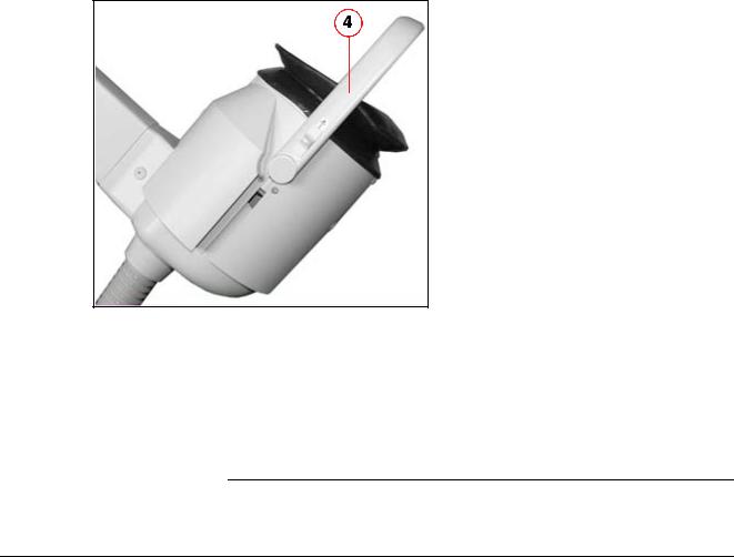
Unpacking LITHOSTAR MODULARIS Vario
Fig. 2: Head, complete
|
|
|
|
|
|
NOTICE |
|
Do not pull on the focus phantom (bracket (4/Fig. 2 / p. 10)), risk of |
|
|
|
|
damage! |
|
|
|
|||
|
|
|
||
|
|
|
|
Do not use the phantom as a handle. |
•Remove the packaging above the unit.
MODULARIS Litho Vario |
SPL1-130.814.02.07.02 |
Page 10 of 88 |
Siemens AG |
|
02.05 |
CS PS 24 |
Medical Solutions |
Installation |
11 |
||||
|
|
|
|
|
|
|
|
|
|
|
|
|
|
|
|
|
|
|
|
|
|
|
|
|
|
|
|
|
|
|
|
|
|
|
|
|
|
|
|
|
|
Fig. 3: Ramp 01
Fig. 4: Ramp 2
•Remove the transport safety screw (1/Fig. 3 / p. 11) used to secure the unit and the ramp (2/Fig. 3 / p. 11).
•Remove all transport safety brackets (3/Fig. 3 / p. 11).
•Slide the ramp (5/Fig. 4 / p. 11) out of the transport pallet from the back to the front and position it appropriately.
•Move the unit off the transport pallet and down the ramp.
•Appropriately dispose of the packaging according to the country-specific regulations.
•Adapt the power cord to the country-specific requirements, if required. If necessary, materials will have to be purchased locally. Use a hospital grade plug for the USA and for Canada.
•Secure the operating panel bracket with the screws.
•Connect the operating panel.
Siemens AG |
SPL1-130.814.02.07.02 |
Page 11 of 88 |
MODULARIS Litho Vario |
Medical Solutions |
02.05 |
CS PS 24 |
|

12 |
Installation |
•Place the control panel in the mount.
Docking unit
NOTE
NOTE
This chapter first describes mechanical coupling for Vario in combination with SIREMOBIL Compact. The differences with regard to the combination with SIREMOBIL ISO-C with a separate bridge are subsequently illustrated.
The procedure is the same for all C-arm units. Mechanical installation of the bridge on the front extension of the C-arm unit must always be adapted. Technical clarification must be known and in conformance with PG (SPL1-130.890.01...).
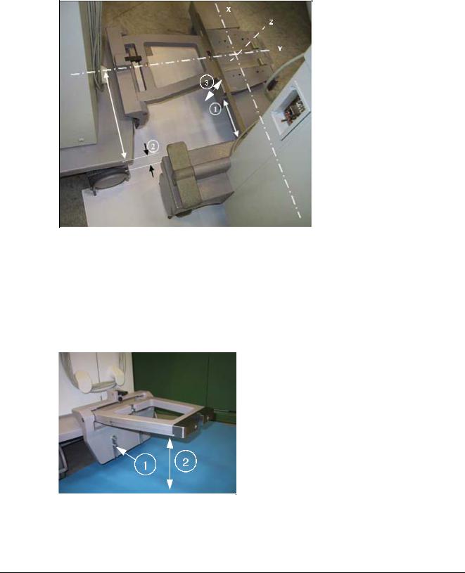
For the sake of clarity regarding technical work on all components, the coordinates are determined in this document in Fig. (Fig. 5 / p. 13) (Vario with shock wave focus, C-arm unit with isocenter, patient table). Side designations left and right are always used for Vario and C-arm unit from the viewpoint of the operator in a forward direction.
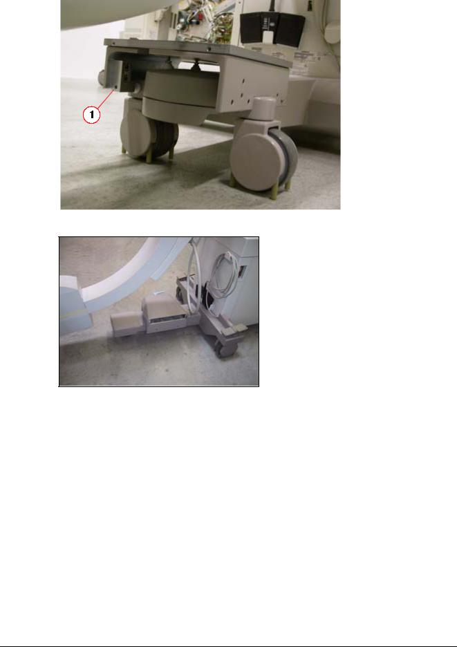
The docking mandrel is pre-installed on the Vario centrally in relation to the longitudinal axis (1/Fig. 5 / p. 13) and can be adjusted by 30 mm in height (200 to 230 mm above the floor). The height is determined depending on the installation of the docking bridge. The docking bridge is installed on the front C-arm unit extension (2/Fig. 5 / p. 13) and
(Fig. 16 / p. 18).
NOTE |
|
The following diagrams are not shown to scale and apply for Vario |
|
|
with Siremobil Compact and Compact L. Pre-clarification by the lo- |
|
||
|
|
cal project management is required for any other C-arm unit. The |
|
|
procedure is then the same. |
|
|
|
MODULARIS Litho Vario |
SPL1-130.814.02.07.02 |
Page 12 of 88 |
Siemens AG |
|
02.05 |
CS PS 24 |
Medical Solutions |

Installation |
13 |
|
|
|
|
|
|
|
Fig. 5: Docking unit
Fig. 6: Docking securing_4
Siemens AG |
SPL1-130.814.02.07.02 |
Page 13 of 88 |
MODULARIS Litho Vario |
Medical Solutions |
02.05 |
CS PS 24 |
|
14 |
|
Installation |
|
|
|
|
|
|
Fig. 7: Docking securing_2
Fig. 8: Docking securing_3
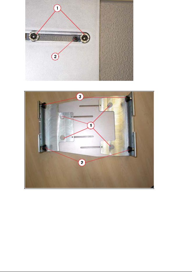
•Prepare the Vario to the left of the C-arm on a level floor (fix C-arm)
•Set the C-arm vertically to approx. 1070 mm in the center ((3/Fig. 5 / p. 13)_ Z direction)
•Remove the top part of the docking bridge.
•Unscrew the docking bridge (1/Fig. 6 / p. 13) or detailed view (1/Fig. 7 / p. 14) and pull the docking bridge apart so that the complete adjustment range is available.
•Place the bottom part of the docking bridge on the C-arm extension, min. 140 mm in the X direction (1/Fig. 9 / p. 15) and approximately centered.
•The docking bridge can be positioned horizontally via Allen screws (2/Fig. 7 / p. 14). If the adjustment range is insufficient, the preinstalled Allen screws (1/2/3/Fig. 8 / p. 14) can be replaced with the included longer screws.
MODULARIS Litho Vario |
SPL1-130.814.02.07.02 |
Page 14 of 88 |
Siemens AG |
|
02.05 |
CS PS 24 |
Medical Solutions |
Installation |
15 |
•Tighten the eight fastening screws (1/Fig. 6 / p. 13) and (Fig. 7 / p. 14).
•Set the Vario docking mandrel in the horizontal position (1/Fig. 5 / p. 13).
•Set the Vario arm to be horizontal (gel or therapy position)
•When the Vario moves in, the mandrel must move over the lower part of the sleeve - check heights from the floor (2/Fig. 10 / p. 15). Adjusting screws for adjusting the height of the mandrel, see (1/Fig. 10 / p. 15). Use a level for this adjustment.
Fig. 9: Docking unit 2
•Move Vario in with a distance of at least 90 mm (2/Fig. 9 / p. 15).
•Align the lower part of the docking bridge to the mandrel in X direction (1/Fig. 9 / p. 15).
•Secure the bottom part with the Allen screw (1/Fig. 11 / p. 16).
•Position the top part of the docking bridge and secure it (1/Fig. 12 / p. 16).
•Test the inward movement and locking of the Vario. The latch must lock securely. Correction is performed using the black Allen screw in the latch (2/Fig. 12 / p. 16).
Fig. 10: View 1
Siemens AG |
SPL1-130.814.02.07.02 |
Page 15 of 88 |
MODULARIS Litho Vario |
Medical Solutions |
02.05 |
CS PS 24 |
|
16 |
|
Installation |
|
|
|
|
|
|
Fig. 11: Lower part_
Fig. 12: Upper part
MODULARIS Litho Vario |
SPL1-130.814.02.07.02 |
Page 16 of 88 |
Siemens AG |
|
02.05 |
CS PS 24 |
Medical Solutions |
Installation |
17 |
|
|
|
|
|
|
|
Fig. 13: Block
Fig. 14: Block_
Siemens AG |
SPL1-130.814.02.07.02 |
Page 17 of 88 |
MODULARIS Litho Vario |
Medical Solutions |
02.05 |
CS PS 24 |
|
18 |
|
Installation |
|
|
|
|
|
|
Fig. 15: Block_mounted
Fig. 16: View 3
.
Combination with ARCADIS Orbic/SIREMOBIL
The bridge is to be modified for ARCADIS Orbic and SIREMOBIL ISO-C according to (Fig. 13 / p. 17).
•Remove both clamping screws (3/Fig. 8 / p. 14).
•Screw the clamping screws from the enclosed material into the fastening block (1 und 2/Fig. 13 / p. 17).
•Attach these blocks to the bridge with 2 screws (3/Fig. 13 / p. 17).
•Position the bridge according to (Fig. 14 / p. 17).
•Horizontally position the bridge via the clamping screw (1/Fig. 14 / p. 17) (or see (2/Fig. 7 / p. 14) for more detail).
•Secure the bridge with the clamping screw (2/Fig. 14 / p. 17) and (1/Fig. 15 / p. 18).
MODULARIS Litho Vario |
SPL1-130.814.02.07.02 |
Page 18 of 88 |
Siemens AG |
|
02.05 |
CS PS 24 |
Medical Solutions |
Installation |
19 |
•Position the top part of the docking bridge and secure it (1/Fig. 12 / p. 16).
•Test the inward movement and locking of the Vario. The latch must lock securely. Correction is performed using the black Allen screw in the latch (2/Fig. 12 / p. 16).
Unit association - labeling
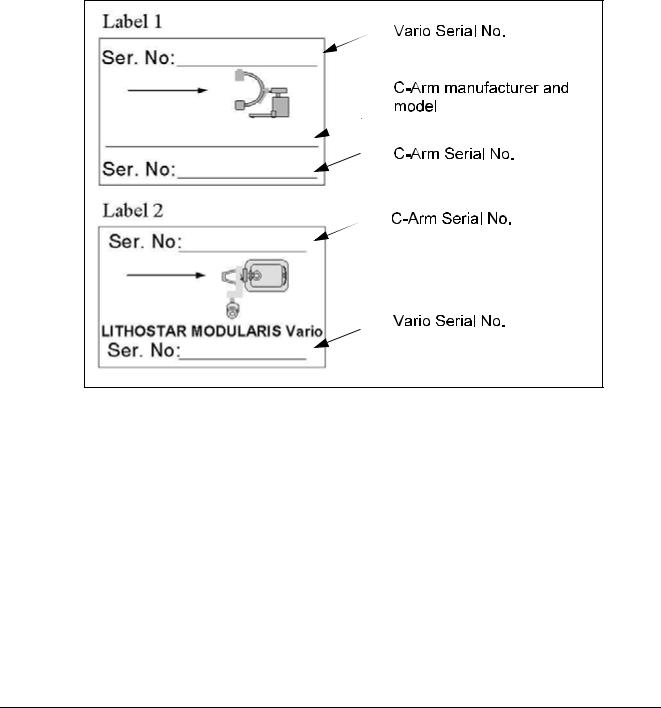
Label the supplied sticker with a permanent marker as shown in Figure: (Fig. 17 / p. 19). All combinable C-arm units must be listed on the Vario. The combinable Vario must be labeled on the C-arm unit. Attach label 1 (Figure (1/Fig. 17 / p. 19)) to the Vario (Figure: (1/Fig. 18 / p. 20)). Attach label 2 (Figure: (Fig. 17 / p. 19)) to the C-arm unit in one of the indicated areas (Figure: (2/Fig. 18 / p. 20)) so that no manufacturer information is covered. Cover both labels with a transparent film.
Fig. 17: Label 1
Siemens AG |
SPL1-130.814.02.07.02 |
Page 19 of 88 |
MODULARIS Litho Vario |
Medical Solutions |
02.05 |
CS PS 24 |
|
20 |
|
Installation |
|
|
|
|
|
|
Fig. 18: Label 2
C-arm unit isocenter cross
Fig. 19: Cross
Fig. 20: I.I. 1
MODULARIS Litho Vario |
SPL1-130.814.02.07.02 |
Page 20 of 88 |
Siemens AG |
|
02.05 |
CS PS 24 |
Medical Solutions |
Installation |
21 |
|
|
|
|
|
|
|
Fig. 21: I.I. 2
Fig. 22: 3 cm I.I.
Attachment of the isocenter cross to the SIREMOBIL Compact and Compact L
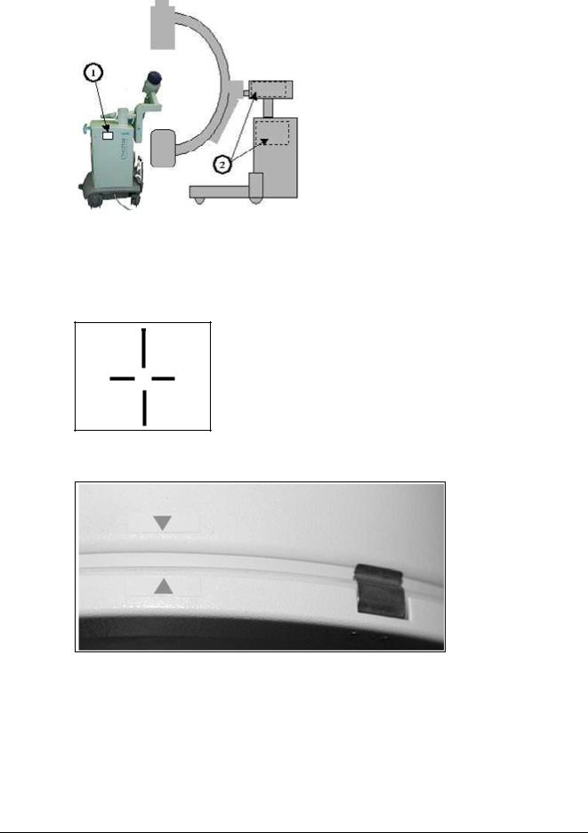
•Remove the front screw on the I.I. and replace it with the M4 x 16 screw included in the shipment (1/Fig. 22 / p. 21).
•The crosshairs must be position in the center of the mounting ring. Check this with a tape measure and correct it if necessary.
•Snap the isocenter cross onto the I.I.
•Attach the arrows (Figure: (Fig. 20 / p. 20)) (indicating the centering stud).
•Place the supplied "serial number" labels on the isocenter cross (1/Fig. 22 / p. 21) and the I.I. (2/Fig. 22 / p. 21).
External isocenter cross manufacturer
Depending on the I.I. diameter, select one of the three delivered crosshairs and attach the corresponding retaining brackets.
•Install the movable bracket (3/Fig. 22 / p. 21) in the crosshair extension.
•Install the two fixed brackets accordingly (4/Fig. 22 / p. 21).
Siemens AG |
SPL1-130.814.02.07.02 |
Page 21 of 88 |
MODULARIS Litho Vario |
Medical Solutions |
02.05 |
CS PS 24 |
|

22 |
Installation |
•To allow for later adjustment, tighten the adjusting screw (5/Fig. 22 / p. 21) only loosely. Use the center threaded hole first.
•Mount the grid and position it approximately in the middle.
•Attach the C-arm unit and the Litho module.
•Swing up the adjustment phantom on the shock wave head.
•Center the grid with the adjustment phantom under fluoroscopy by moving the retaining brackets.
•Install the second screw in the retaining brackets and check again that the grid is centered.
•Adhere the arrows (6/Fig. 22 / p. 21) to the I.I.
Radiation release option
NOTE |
|
|
The radiation release option of the Lithostar operating panel is re- |
||
|
leased only for Siremobil Compact and Compact L. |
|
|
||
|
|
|
This option is performed according to the instructions SPR2-130.814.05... "Installation Instructions for LITHOSTAR Modularis Vario". A paper version of this document is part of conversion kit number 71 40 952.
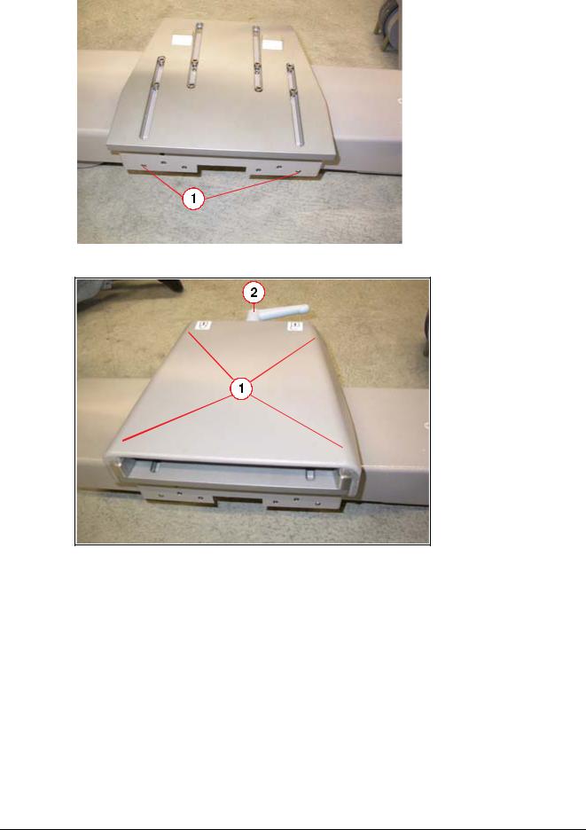
MODULARIS Uro Table
Installing the positioning yoke
•The positioning yoke is packed separately in the shipment (part no. 81 25 333).
•Attach the yoke to the table with the two screws as shown in ((1/Fig. 23 / p. 23)).
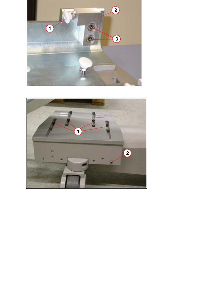
•The positioning yoke must be adjusted so that its height corresponds to that of the docking bridge ((1/Fig. 24 / p. 23)). Adjustment can be performed by turning the two rubber stoppers ((2/Fig. 24 / p. 23)).
•The rubber stoppers must be secured by the screw ((1/Fig. 25 / p. 24)).
•No mechanical connection is created when operating the system for therapeutic purposes. The C-arm is simply docked in the yoke.
•The yoke must be collapsed to the table base and rest completely on it when in the table park position.
MODULARIS Litho Vario |
SPL1-130.814.02.07.02 |
Page 22 of 88 |
Siemens AG |
|
02.05 |
CS PS 24 |
Medical Solutions |

Installation |
23 |
||
|
|
|
|
|
|
|
|
|
|
|
|
Fig. 23: Positioning_yoke_1
Fig. 24: Positioning_yoke_2
Siemens AG |
SPL1-130.814.02.07.02 |
Page 23 of 88 |
MODULARIS Litho Vario |
Medical Solutions |
02.05 |
CS PS 24 |
|

24 |
|
Installation |
|
|
|
|
|
|
|
|
|
|
|
|
|
Fig. 25: Securing screw
Fig. 26: Positioning yoke
MODULARIS Litho Vario |
SPL1-130.814.02.07.02 |
Page 24 of 88 |
Siemens AG |
|
02.05 |
CS PS 24 |
Medical Solutions |

Installation |
25 |
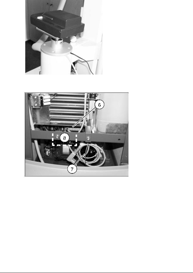
ECG triggering option
Mounting the docking station
•Unscrew the rectangular plate (Fig. 27 / p. 26) from the docking station of the ECG monitor. It is no longer required.
•Screw the docking station bracket from the conversion kit onto the round plate so that the longitudinal grooves are visible from below (Fig. 28 / p. 26).
•Remove the round cap from the column of the system trolley. It is no longer required.
•Remove the cover from the system trolley.
•Disconnect the cables from the mount (7/Fig. 30 / p. 27).
•Plug the inlet connector for a non-heating apparatus (power cable) into the connector strip (6/Fig. 30 / p. 27).
•Push the trigger cable from the D3.X70 board (beside the service switch) starting with the jack plug, from beneath, through the column and lead it out, parallel to the wires, together with the power cable.
•Plug the inlet connector for a non-heating apparatus into the power supply unit of the ECG monitor.
•Attach the power supply unit of the ECG monitor in the system cart to the support (8/Fig. 30 / p. 27) via cable clamps.
•Push the 24 V cable of the power unit through the column from below and route it in the same way as the trigger cable.
•Using a cable clamp for each from the conversion kit, secure both cables to the mounting plate so that a length of approximately 35 cm is available outside the column.
•Screw the plate firmly onto the column so that the cables emerge from the corrugated hose opposite each other, as shown in (Fig. 29 / p. 27).
•Connect the service PC.
•Select the ECG function according to the service instructions.
Siemens AG |
SPL1-130.814.02.07.02 |
Page 25 of 88 |
MODULARIS Litho Vario |
Medical Solutions |
02.05 |
CS PS 24 |
|

26 |
|
Installation |
|
|
|
|
|
|
Fig. 27: Attachment 1
Fig. 28: Attachment 2
MODULARIS Litho Vario |
SPL1-130.814.02.07.02 |
Page 26 of 88 |
Siemens AG |
|
02.05 |
CS PS 24 |
Medical Solutions |
Installation |
27 |
|
|
|
|
|
|
|
Fig. 29: Attachment 3
Fig. 30: Attachment 4
Siemens AG |
SPL1-130.814.02.07.02 |
Page 27 of 88 |
MODULARIS Litho Vario |
Medical Solutions |
02.05 |
CS PS 24 |
|
Loading...