Siemens Mammomat 3000 Opdima Wiring Diagrams

MAMMOMAT 3000 Opdima™
Digital Biopsy and Spot Imaging System
Wiring Diagram
© Siemens AG 1997
The reproduction, transmission or use of this document or its contents is not permitted without express written authority. Offenders will be liable for damages. All rights, including rights created by patent grant or registration of a utility model _or_ design,_are_ reserved.
Register 6 |
English |
|
Print No.: SPB7-230.051.04.01.02 |
Release Date: |
06.97 |
Replaces:
64 28 234

Revision
Chapter |
Page |
Rev. |
|
|
|
|
|
|
|
|
|
|
|
|
|
|
|
|
|
|
|
|
|
Siemens-Elema AB |
SPS-UD |
SPB7-230.051.04 |
Register 6 |
MAMMOMAT 3000 Opdima |
Solna, Sweden |
|
Rev. 01 06.97 |
|
Wiring |

|
Contents |
|
Page 1 of 16 |
General ........................................................................................ |
3 |
Documents required ........................................................................................... |
3 |
System overview ........................................................................ |
4 |
General ............................................................................................................... |
4 |
Location of components ..................................................................................... |
5 |
Cable connections .............................................................................................. |
7 |
Functional diagrams .................................................................. |
8 |
Block diagram ..................................................................................................... |
8 |
Power supply and ground connections ............................................................... |
9 |
Biopsy unit potentiometers/display ................................................................... |
10 |
CCD camera and RS-232 communication ....................................................... |
11 |
List of components .................................................................. |
12 |
Fuses ................................................................................................................ |
12 |
Printed circuit boards ........................................................................................ |
12 |
Potentiometers ................................................................................................. |
14 |
Miscellaneous ................................................................................................... |
14 |
List of testpoints and LEDs ..................................................... |
15 |
Testpoints ......................................................................................................... |
15 |
LEDs ................................................................................................................. |
16 |
Siemens-Elema AB |
SPS-UD |
SPB7-230.051.04 |
Register 6 |
MAMMOMAT 3000 Opdima™ |
Solna, Sweden |
|
Rev. 01 06.97 |
|
Wiring |

Contents
Page 2 of 16
MAMMOMAT 3000 Opdima™ |
Register 6 |
SPB7-230.051.04 |
SPS-UD |
Siemens-Elema AB |
Wiring |
|
Rev. 01 06.97 |
|
Solna, Sweden |

General
Page 3 of 16
General
This document shows the electrical connections, electrical components and testpoints within the Opdima™ system.
Documents required
The following document is referred to in this manual:
∙ MAMMOMAT 3000 Wiring Diagram
Siemens-Elema AB |
SPS-UD |
SPB7-230.051.04 |
Register 6 |
MAMMOMAT 3000 Opdima™ |
Solna, Sweden |
|
Rev. 01 06.97 |
|
Wiring |

System overview
Page 4 of 16
System overview
General
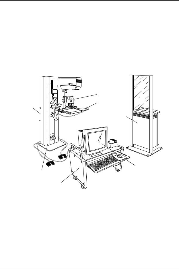
The digital biopsy and spot imaging system Opdima™ is an option to the MAMMOMAT 3000. Opdima™ consists of:
∙Workstation
∙Biopsy controller
∙CCD camera
The biopsy controller is the central unit for the cable connections in the Opdima™ system.
|
Mammomat 3000 |
|
Biopsy unit |
Biopsy |
CCD camera |
controller |
|
Generator
Stand with
X-ray unit
Trolley (option)
Workstation
95720018
Figure 1 Opdima™ subassemblies
MAMMOMAT 3000 Opdima™ |
Register 6 |
SPB7-230.051.04 |
SPS-UD |
Siemens-Elema AB |
Wiring |
|
Rev. 01 06.97 |
|
Solna, Sweden |
 Loading...