


Instruction Manual  November 2005
open channel 
OCM III

Safety Guidelines: Warning notices must be observed to ensure personal safety as well as that of others, and to protect the product and the connected equipment. These warning notices are accompanied by a clarification of the level of caution to be observed.
Qualified Personnel: This device/system may only be set up and operated in conjunction with this manual. Qualified personnel are only authorized to install and operate this equipment in accordance with established safety practices and standards.
Unit Repair and Excluded Liability:
•The user is responsible for all changes and repairs made to the device by the user or the user’s agent.
•All new components are to be provided by Siemens Milltronics Process Instruments Inc.
•Restrict repair to faulty components only.
•Do not reuse faulty components.
Warning: This product can only function properly and safely if it is correctly transported, stored, installed, set up, operated, and maintained.
Note: Always use product in accordance with specifications.
Copyright Siemens Milltronics Process |
Disclaimer of Liability |
Instruments Inc. 2005. All Rights Reserved |
|
This document is available in bound version and in |
While we have verified the contents of this |
electronic version. We encourage users to purchase |
manual for agreement with the |
authorized bound manuals, or to view electronic versions |
instrumentation described, variations |
as designed and authored by Siemens Milltronics Process |
remain possible. Thus we cannot |
Instruments Inc. Siemens Milltronics Process Instruments |
guarantee full agreement. The contents of |
Inc. will not be responsible for the contents of partial or |
this manual are regularly reviewed and |
whole reproductions of either bound or electronic |
corrections are included in subsequent |
versions. |
editions. We welcome all suggestions for |
|
improvement. |
|
Technical data subject to change. |
MILLTRONICS®is a registered trademark of Siemens Milltronics Process Instruments Inc.
Contact SMPI Technical Publications at the following address:
Technical Publications
Siemens Milltronics Process Instruments Inc. 1954 Technology Drive, P.O. Box 4225 Peterborough, Ontario, Canada, K9J 7B1 Email: techpubs.smpi@siemens.com
•For a selection of Siemens Milltronics level measurement manuals, go to:
www.siemens.com/processautomation. Under Process Instrumentation, select Level Measurement and then go to the manual archive listed under the product family.
•For a selection of Siemens Milltronics weighing manuals, go to:
www.siemens.com/processautomation. Under Weighing Technology, select Continuous Weighing Systems and then go to the manual archive listed under the product family.
© Siemens Milltronics Process Instruments Inc. 2005

TABLE OF CONTENTS
TITLE |
PAGE |
ABOUT THIS ... |
|
About This Manual |
7 |
About the OCM-3 |
7 |
SPECIFICATIONS |
9 |
Programmer |
10 |
Transducer |
11 |
Temperature Sensor |
11 |
Cabling |
11 |
Communication Software |
11 |
INSTALLATION |
|
Installing the OCM-3 |
13 |
Outline and Mounting |
13 |
OCM-3 Layout |
14 |
System Diagram |
15 |
Installing the Transducer |
16 |
Installing the Temperature Sensor |
16 |
mA Output |
17 |
Relays |
17 |
Synchronization |
18 |
Power Connections |
19 |
Installing the Memory Back-up Battery |
20 |
Communicating Via Computer |
20 |
Installing the Programmer |
20 |
7ML19985AB01 |
OCM III |
3 |
START UP |
|
General |
21 |
Keypad |
21 |
Legend |
22 |
Initial Start Up |
22 |
Fundamental Checks |
25 |
OPERATION |
|
Memory |
27 |
Security |
27 |
Units |
27 |
Flow Calculation |
28 |
Display |
28 |
Damping |
29 |
Relays |
30 |
mA Output |
30 |
Fail-Safe |
31 |
Flow rate and Totalizing |
31 |
Logging |
32 |
Blanking |
34 |
Temperature |
34 |
Time and Date |
34 |
Emulation Mode |
35 |
Reset |
35 |
Flow Velocity Input |
36 |
Auxiliary Head Input |
36 |
DC Output |
37 |
Diagnostic Aids |
37 |
7ML19985AB01 |
OCM III |
4 |
‘D’ PARAMETER LISTING |
39 |
‘F’ PARAMETER LISTING |
41 |
‘P’ PARAMETER LISTING |
43 |
‘U’ PARAMETERS FOR P3 PRIMARY ELEMENT |
51 |
Simple Exponential Devices, P3 = 0 |
53 |
BS-3680 Rectangular Flume, P3 = 1 |
58 |
BS-3680 Round Nose Horizontal Crest Weir, P3 = 2 |
60 |
BS-3680 Trapezoidal Flume, P3 = 3 |
62 |
BS-3680 U - Flume, P3 = 4 |
64 |
BS-3680 Finite Crest Weir, P3 = 5 |
66 |
BS-3680 Thin Plate Rectangular Weir, P3 = 6 |
68 |
BS-3680 Thin Plate V-Notch Weir, P3 = 7 |
70 |
Rectangular Weir (Contracted), P3 = 8 |
72 |
Round Pipe, P3 = 9 |
74 |
Palmer-Bowlus Flume, P3 = 10 |
76 |
H - Flume, P3 = 11 |
78 |
Universal Head vs. Flow, P3 =12 |
80 |
Rectangular Area x Velocity, P3 = 13 |
82 |
Trapezoidal Area x Velocity, P3 =14 |
84 |
Modified Trapezoidal Area x Velocity, P3 = 15 |
86 |
U Channel Area x Velocity, P3 = 16 |
88 |
Circular Area x Velocity, P3 = 17 |
90 |
Gull-Wing Area x Velocity, P3 = 18 |
92 |
Egg-Shaped Area x Velocity, P3 =19 |
94 |
Universal Area x Velocity, P3 = 20 |
96 |
APPENDICES |
|
Maintenance |
99 |
Error Codes |
100 |
Communications |
101 |
7ML19985AB01 |
OCM III |
5 |

7ML19985AB01 |
OCM III |
6 |

ABOUT THIS ...
ABOUT THIS MANUAL
Although the OCM-3 is very ‘approachable’ due its dialogue capabilities and intuitive operation, the user should be familiar with this manual. This manual provides the user with the necessary information required to install, start up and operate the OCM-3.
As the OCM-3 prompts the user with specific messages in a step-by-step fashion during programming, the Start Up section serves essentially to compliment the OCM-3. Start Up provides the user with instructions on the use of the programmer and an overview of the programming requirements.
The ‘D’, ‘F’, ‘P’ and ‘U’ parameters listed in the Parameters section provide a quick reference of the available programming and display parameters and their options. The ‘U’ parameter listing also provides mathematical and graphical details as a reference to assist the user in programming the OCM-3 to the primary element being used. The user is urged to rely on the manufacturer’s specification for obtaining and identifying the primary element to which the OCM-3 is being applied.
In short,
If you want to know about |
Read |
the product |
About This . . . |
|
Specifications |
getting started |
Installation |
|
Start Up |
how it works |
Operation |
|
Parameters |
|
Appendices |
ABOUT THE OCM-3
The OCM-3 is to be used only in the manner outlined in this instruction manual.
The Milltronics OCM-3, Open Channel Meter, is an electronic instrument designed to measure flow in open channels. It is housed in a polycarbonate enclosure and comes with a removable programmer. As a system, it is used in conjunction with a remote ultrasonic transducer (or auxiliary head measurement device) and a temperature sensor.
The OCM-3 transmits a pulse signal to the transducer which is then emitted as ultrasonic pulses. The pulses echo off the water surface and are then sensed by the transducer. The time for a pulse to echo back from the water surface is temperature compensated and converted into a measurement of head.
7ML19985AB01 |
OCM III |
7 |
The OCM-3 converts the head measurement into flow rate, but also provides a velocity sensor input for applications where a flow velocity measurement is required to perform the flow calculation. The flow rate is totalized and stored in a comprehensive data log to provide detailed flow analysis.
Programming of the OCM-3 allows the operator to select the flow calculation specific to the primary measuring device (flume, weir or pipe). Special emphasis has been placed on providing the most accurate flow calculations possible. To this end, specific routines have been written to comply with the British Standards Institute’s Specifications BS-3680. These routines calculate correction factors taking into account second order effects such as approach velocity and boundary layer. In the event that flow measurement is not covered by one of the flow calculations provided, the OCM-3 can be programmed for flow measurement using one of the universal flow calculations.
The OCM-3 provides serial communication for remote programming, data log retrieval and print out for devices such as computers, PLCs and printers. Milltronics provides a standard utilities software package for OCM-3 programming, remote display and data retrieval. However, the user is not limited to the software provided. The user can develop his own software program to perform tasks suited to his specific needs.
The OCM-3 features:
multi field illuminated LCD, for ‘Flow and Total’ and ‘Relay Status’ display
0 or 4 to 20 mA output
three multipurpose relays, including remote totalization
1 to 24 months data log, subject to logging rate
extensive serial communication, including RS-232
removable infra-red programmer
AC and DC (bi-current) operation.
7ML19985AB01 |
OCM III |
8 |

SPECIFICATIONS
Power: |
» dc supply: |
» 9 to 30 V DC, 8 W max and / or |
|
|
» ac supply: |
» 100/115/200/230 V ac ± 15%, 50/60 Hz, |
|
|
|
20 VA max |
|
Environmental: |
» location |
|
» indoor /outdoor |
|
» altitude: |
|
» 2000 m max |
|
» ambient temperature |
» – 20 to 50 °C (–5 to 122 °F) |
|
|
» relative humidity |
|
» suitable for outdoor (Type 4X/Nema 4X |
|
|
|
IP65 enclosure) |
|
» installation category |
» II |
|
|
» pollution degree |
|
» 4 |
Memory |
|
|
|
back-up: |
» 3 V lithium battery (NEDA 5003LC or equivalent) |
||
»operating life 1 year
»‘SuperCap’ capacitor for back-up during battery replacement
Range: |
» 0.3 m min to 1.2 m max ( 1 to 4 ft) |
|
|
|
0.6 m min to 3 m max (2 to 10 ft) |
|
|
Resolution: |
» 0.2 mm (0.007") |
|
|
Accuracy: |
» ±1 mm/m, calculated error less than 0.02% |
||
Temperature |
|
|
|
Compensation: |
» external sensor to compensate over |
|
|
|
the operating range |
|
|
Programming: |
» via supplied programmer and |
|
|
|
communication link |
|
|
Inputs: |
» velocity sensor and |
|
|
|
auxiliary head |
» range: |
» 0 to 10 V dc |
|
|
» resolution: |
» 2.7 mV |
Outputs: |
» transducer drive: » 44 Khz, 400 Vpp pulses of 0.1 msec typical |
||
|
|
duration at a 100 msec typical repetition rate. |
|
|
» instrumentation: |
» range: |
0-20 or 4-20 mA |
|
|
» resolution: |
5 uA |
|
|
» maximum loading: |
1 KΩ |
7ML19985AB01 |
OCM III |
9 |

|
» isolation: |
300 V ac continuous |
» relays: |
» 3 alarm/control relays |
|
|
» 1 form ’C’ SPDT contact per relay, rated at |
|
|
5 A at 250 V ac non-inductive or 30 V dc |
|
» dc output: |
» +24 V dc |
|
|
» 20 mA average to 200 mA at 1/10 duty |
|
|
cycle max |
|
Communication: » RS-232 or ± 20 mA bipolar current loop,300,
600, 1200, 2400, 4800, 9600 or 19200 baud
Data Logs: |
» variable rate on 1, 5, 15, 30 or 60 min or 24 hr |
|
» 31 days minimum/2 years maximum |
Display: |
» illuminated liquid crystal 5 x 7 dot matrix |
|
display with 2 lines of 40 characters each |
Enclosure: |
»Type 4X / NEMA 4X / IP65 |
|
» 209 mm W x 285 mm H x 92 mm D |
|
(8.2" W x 11.2" H x 3.6" D) |
|
» polycarbonate |
Weight: |
» 2.3 Kg (5.1 lb) |
Approvals: |
» CE *, FM, CSA NRTL/C |
|
» MCERTS Class 1 open channel flow device with environment |
|
operation limits at 35 °C (95 °F) at 93% relative humidity |
|
SIRA MC 050058/01 |
PROGRAMMER |
|
Enclosure: |
» general purpose |
|
» 67 mm W x 100 mm H x 25 mm D |
|
(2.6" W x 4" H x 1" D) |
|
» ABS plastic |
Operating Temperature: |
» –20 to 50 °C (–5 to 122 °F) |
7ML19985AB01 |
OCM III |
10 |
Battery: |
|
» 9 V (ANSI / NEDA 1604, PP3 or equivalent) or |
|
|
3V lithium battery |
TRANSDUCER |
|
|
Model: |
» XRS-5* |
|
|
Refer to associated Transducer manual. |
|
TEMPERATURE SENSOR |
|
|
Model: |
» TS-2, LTS-1 or LTS-1C |
|
|
Refer to associated Temperature Sensor manual. |
|
CABLING |
|
|
Transducer: |
|
» RG-62U coaxial |
|
|
» maximum separation 183 m (600 ft) |
|
|
» must be run in grounded metal conduit |
mA Output: |
|
» Belden 8760 or equivalent |
Synchronisation: |
|
» Belden 8760 |
Temperature Sensor: |
» Belden 8760, 1 pair shielded/twisted, |
|
18 AWG or equivalent
» maximum separation 183 m (600 ft)
» can be run in conduit with transducer cable
Communication: » RS-232: » Belden 8770, 3 wire shielded, 24 AWG or equivalent
»maximum separation 15 m (50 ft)
»Bipolar Current: » Belden 9552, 2 pair shielded/twisted,
18 AWG or equivalent
» maximum separation 1,500 m (5,000 ft)
*Note: The XRS-5 must be used with the TS-2 external temperature sensor when operating with the OCM-3.
Velocity Input: |
» Belden 8760 or equivalent |
7ML19985AB01 |
OCM III |
11 |

Auxiliary Input: |
» Belden 8760 or equivalent |
24 V Output: |
» Belden 8760 |
COMMUNICATION SOFTWARE
Milltronics Utilities Software on standard PC floppy disk for DOS 3.1 and up.
7ML19985AB01 |
OCM III |
12 |

INSTALLATION
Installation shall only be performed by qualified personnel and in accordance with local governing regulations.
INSTALLING THE OCM-3
The OCM-3 should be mounted in a clean, dry area that is: within the ambient temperature range and suitable for the specified enclosure. The front cover should be accessible for programming and viewing.
It is advisable to keep the OCM-3 away from high voltage or current runs, contactors and SCR control drives.
Do not mount the OCM-3 in direct sunlight without the use of a sun shield.
This product is susceptible to electrostatic shock.
Follow proper grounding procedures.
OUTLINE AND MOUNTING
|
209 mm |
|
106 mm |
|
16 mm |
(8.2") |
|
||
|
lid screws |
(4.2") |
||
(0.6") |
172 mm |
|||
91 mm |
||||
|
(6.8") |
(6 places) |
||
|
|
(3.6") |
||
|
|
|
||
|
|
285 mm |
|
|
|
|
(11.2") |
|
|
|
|
|
programmer |
|
267 mm |
|
|
(10.5") |
|
suitable location for |
mounting holes |
lid |
|
||
conduit entrances |
(accessed under |
enclosure |
|
lid 4.3 mm (0.17") |
|
Milltronics reccomends using a punch for making |
|
|
dia.,4 places |
customer mounting |
|
holes in enclosure. Use suitable cable glands to |
|
|
maintain ingress rating. |
|
screw |
Non metallic enclosure does not provide grounding between connections. Use grounding type bushings and jumpers.
13 |
OCM III |
7ML19985AB01 |

OCM-3 LAYOUT
board A
display board
board B
 All field wiring must have insulation suitable for at least 250 V.
 Hazardous voltage present on transducer terminals during operation.
dc terminals shall be supplied from SELV source in accordance with IEC 1010-1 Annex H.
Relay contact terminals are for use with equipment having no accessible live parts and wiring having insulation suitable for at least 250 V.
The maximum allowable working voltage between adjacent relay contacts shall be 250 V.
14 |
OCM III |
7ML19985AB01 |
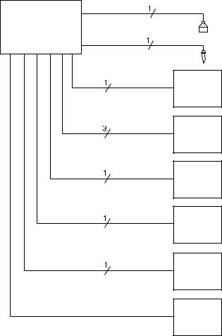
SYSTEM DIAGRAM
OCM-3
mA output
relay output
auxiliary input
velocity input
RS-232
bi-polar current
(Milltronics communication)
Milltronics transducer, see Specifications
Milltronics TS-2, temperature sensor
customer device
customer alarm, pump or control device
customer device
customer device
customer device
Milltronics CVCC
Maximum system capability. Not all components or their maximum quantity may be required.
15 |
OCM III |
7ML19985AB0198/03/05 |

INSTALLING THE TRANSDUCER
Max cable run 183 m (600 ft) of RG-62U or equivalent. Cable must be run in a grounded metal conduit with no other cabling (except Temp. Sensor cable).
Ground shield at OCM-3 only.
Insulate shield at junctions to prevent inadvertent grounding.
Basic Wiring – Transducer
Hazardous voltage present on transducer terminals during operation.
Note: When using the XRS-5 transducer with the OCM-3, use the TS-2 external temperature sensor. The internal temperature sensor in the XRS-5 cannot be used.
INSTALLING THE TEMPERATURE SENSOR
In order to compensate for uniform temperature change in the air between the transducer and the flow surface, the temperature sensor must be connected to the OCM-3.
Maximum cable run 183 m (600 ft) of Beldon 8760, 1 pair shielded/twisted, 18 AWG or equivalent.
Temperature sensor cable can be run with the transducer cable in a grounded metal conduit.
Ground shield at OCM-3 only.
Basic Wiring – Temperature Sensor
16 |
OCM III |
7ML19985AB01 |
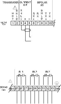
mA OUTPUT
isolated 0 or 4 to 20 mA output (P26) into 1 KΩ load maximum.
Wiring should conform to standard instrumentation practices. Ground shield at OCM-3 only.
RELAYS
relays shown in de-energized state, contacts rated at 5 A at 250 V non-inductive.
n.c. com n.o. n.c. com n.o. n.c. com n.o.
All relays are certified for use in equipment where the short circuit capacity of the circuits in which they are connected is limited by fuses having ratings not exceeding the rating of the relays.
17 |
OCM III |
7ML19985AB01 |
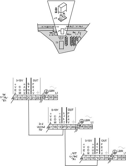
SYNCHRONIZATION
Where two to a maximum of twelve transducers will be sharing a common conduit the OCM-3s should be synchronized. In order to synchronize OCM-3s:
» remove jumper J1 on board A on all but one OCM-3
»interconnect the SYNC terminal (TB1-20) of all OCM-3s. Insure that all OCM-3s share a common ground (TB1-34).
18 |
OCM III |
7ML19985AB01 |
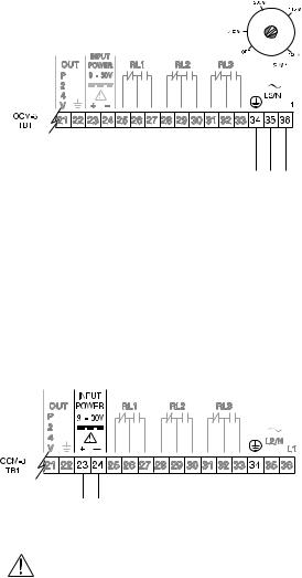
POWER CONNECTIONS
The OCM-3 power supply accepts 100, 115, 200 or 230 V ac per switch SW1 (board B) selection and 9 to 30 V dc.
The OCM-3 operates either under ac or dc power, or both ac and dc live simultaneously. If both ac and dc power are live, the OCM-3 normally draws power from the ac supply. In the event that the ac supply fails, the OCM-3 then draws power from the dc supply.
AC POWER
* |
* switch shown in |
|
‘OFF’ position, |
|
select appropriate |
|
voltage. |
100/115/200/230 V ac, 50/60 Hz, select voltage via switch on board B
The equipment must be protected by a 15 A fuse or circuit breaker in the building installation.
A circuit breaker or switch in the building installation, marked as the disconnect switch, shall be in close proximity to the equipment and within easy reach of the operator.
DC POWER
negative dc input (TB1-24) is 9 to 30 Volt tied to ground (TB1-34)
dc input
dc terminals shall be supplied from SELV source in accordance with IEC 1010-1 Annex H.
19 |
OCM III |
7ML19985AB01 |

INSTALLING THE MEMORY BACK-UP BATTERY
Disconnect power before installing or replacing the battery.
Do not install the memory back-up battery until the OCM-3 is to be used.
The unit is supplied with one battery package. Remove the battery from the package and insert it into the battery socket.
Refer to Operation \ Memory.
The memory battery, B1 (see Specifications) should be replaced yearly to insure memory back up during lengthy power outages. An on board capacitor provides one hour of memory retention in order to preserve the memory while the battery is being changed.
COMMUNICATING VIA COMPUTER
Refer to Communication.
INSTALLING THE PROGRAMMER
To program the OCM-3 via the Programmer, it must be placed into the front cover recess of the OCM-3. The back of the Programmer has a magnetic plate which will hold the programmer in place. It can be removed when programming is completed.
|
|
|
|
|
|
|
|
|
|
|
|
|
|
|
|
|
|
20 |
|
|
OCM III |
7ML19985AB01 |
|
START UP
GENERAL
For the initial start up, it is advisable to use the programmer for programming the OCM-3. The programmer transmits a coded infrared signal each time a key is pressed.
The OCM-3 is designed to automatically scroll through the ‘A’, ‘D’, ‘F’, ‘P’ and ‘U’ parameters in a structured sequence. The scrolling is interactive in that, depending on the option chosen for a given parameter, subsequent parameters may be skipped or modified. The user is thus prompted to satisfy only the parameters which are available to him for the application he has chosen.
KEYPAD
numeric entries with decimal point
access to ‘A’ parameters / initiates a printout while viewing ‘Flow and Total’
|
|
|
|
|
|
|
|
|
|
|
|
|
|
|
|
|
|
|
|
|
|
|
|
|
|
|
|
|
|
|
|
|
|
|
|
|
|
|
|
|
|
|
|
|
|
|
|
|
|
|
|
|
|
|
|
|
|
|
|
|
|
|
|
|
|
|
|
|
|
|
|
|
|
|
|
|
|
|
|
|
|
|
|
|
|
|
|
access to ‘D’, ‘F’, |
|
|
|
|
|
|
|
|
|
|
|
|
|
|
|
|
|
|
|
|
|
|
|
|
|
|
|
|
|
|
|
|
|
|
|
|
|
|
|
|
|
||
|
|
|
|
|
|
|
|
|
|
|
|
|
|
|
|||||||
|
|
|
|
|
|
|
|
|
|
|
|
|
|
|
|
|
|
|
|
||
‘P’ and ‘U’ |
|
|
|
|
|
|
|
|
|
|
|
|
|
scrolls through selected |
|||||||
parameters |
|
|
|
|
|
|
|
|
|
|
|
|
|
parameter options |
|||||||
|
|
|
|
|
|
|
|
|
|
|
|
|
|
|
|
|
|
|
|
|
|
|
|
|
|
|
|
|
|
|
|
|
|
|
|
|
|
|
|
|
|
|
|
|
|
|
|
|
|
|
|
|
|
|
|
|
|
|
|
|
|
|
|
|
|
|
|
|
|
|
|
|
|
|
|
|
|
|
|
|
|
|
|
|
|
|
|
|
|
|
|
|
|
|
|
|
|
|
|
|
|
|
|
|
|
|
|
|
|
|
|
|
|
|
|
|
|
|
|
|
|
|
|
|
|
|
|
|
|
|
|
scrolls Forward through negative the parameters / enters
content of entry field
scrolls Backward through the parameters / clears content of entry field
7ML19985AB01 |
OCM III |
21 |
LEGEND
Press the associated programmer key:
Display shown on OCM-3:
Programmer key:
INITIAL START UP
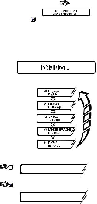
After installation procedures have been completed, the OCM-3 may be powered up. Upon initial powering up, the unit momentarily displays:
and then scrolls through the available languages:
The OCM-3 is asking which language you prefer to communicate in!
0 |
(0) language |
English language |
|
English |
selected |
advance to ‘F0’
F0 enter security code < - - -
7ML19985AB01 |
OCM III |
22 |

2 |
7 |
1 |
8 |
2 |
8 |
factory set security code |
|
2.71828 must be entered |
|||||||
|
|
|
|
|
|
||
|
|
P0 |
language |
if the wrong language |
|||
|
|
was selected, it may |
|||||
|
|
0 |
English |
||||
|
|
|
|||||
be changed here
P1 dimensional units
0centimeters
continue programming by entering the desired options and advancing until the scroll returns to ‘P0’. It is then assumed that the user has entered all the required parameters.
P0 language
0English
For optimum calibration accuracy, an ‘F13’ should be performed prior to accessing ‘F2’, the normal operating mode.
1 3
F13 |
auto zero calibration |
enter the current head. The |
|
|
|
|
OCM-3 calculates ‘P46’ and |
|
|
|
automatically enters the value. |
e.g. 1 6 0 |
|
|
|
1 |
6 |
0 |
|
F13 auto zero calibration
160
F13 auto zero calibration
0completed
7ML19985AB01 |
OCM III |
23 |

If data logging is desired, the time and date must be set.
4
F4 24-hr. time
e.g. 1141
1 |
1 |
4 |
1 |
|
F4 |
24-hr. time |
11: 41 a.m., |
||
|
||||
1141 |
seconds are always |
|
assumed to be 00 |
||
|
F4 |
24-hr. time |
time is displayed in |
11:41:00 |
enter new time |
hh:mm:ss |
F5 (ddmmyyyy) date
e.g. 12101492 |
|
|
|
|
October 12, 1492 |
||
1 |
2 |
1 |
0 |
1 |
4 |
9 |
2 |
F5 |
|
(ddmmyyyy) date |
|
||||
12/10/1492 enter new date
The start up procedure is now complete. Enter ‘F2’ to place the OCM-3 in the normal operating mode.
2
Note: To save parameter values, return to RUN mode (F2) after programming.
The OCM-3 now displays the flow rate and total. Refer to Operation \ Display
7ML19985AB01 |
OCM III |
24 |
FUNDAMENTAL CHECKS
For accurate determination of flowrate, accurate head measurement is essential. Check the following and correct if necessary.
»check D5 for correct temperature at transducer location.
»check D9 for correct distance from transducer to head.
»check D0 for accurate head measurement.
7ML19985AB01 |
OCM III |
25 |

7ML19985AB01 |
OCM III |
26 |

OPERATION
Upon power up, the transducer is fired periodically as set by P36. A long interval between measurements may be desirable in order to conserve power* when operating the OCM-3 from a DC source of limited capacity.
The echo is processed to determine the head (D0). The flow rate (D1) is calculated by the OCM-3 as a mathematical function (P3 and P4) of head or a function of head and velocity (P42). The flow rate is then integrated to yield the totalized flow (D2). The ‘Flow’ and ‘Total’ fields which are displayed during the normal running mode (F2) are also continuously updated.
Viewing or changing the content of a parameter (except F1, emulation) is done without disturbing the acquisition, processing or logging of flow data (see \ Security).
*restricted usage of display lighting (P14), relays (P15, 18 & 21), mA output and communications will also conserve power.
MEMORY
During a power interruption, the memory back up will hold the programming, the log and the totalizer values, and run the clock. The memory battery (B1) provides up to one year of memory retention (see Appendices \ Maintenance).
Note: To save parameter values, return to RUN mode (F2) after programming.
SECURITY
The content of all ‘A’, ‘D’, ‘F’, ‘P’ and ‘U’ parameters can be viewed without having to satisfy the security parameter, F0. However if it is desired to change the content of any of these parameters, the security parameter must be satisfied (except for resetting the running min/max displays, parameters D3/D4 and D6/D7).
Once security has been satisfied, access continues for 5 minutes after the last key is pressed or until F2 is re-entered.
The security code may be changed from its factory set value, 2.71828, by entering a new value into F10. It is imperative that the new value be recorded, as the code can not be viewed. If the code is lost, consult Milltronics.
UNITS
Programming of the OCM-3 involves setting the units of measure:
»P1 linear and velocity
»P2 temperature
»P5 flow rate and volume
If the units are changed during the course of operation, the change will be effected through all associated parameters and displays and will rescale flow and total data stored in the logs.
7ML19985AB01 |
OCM III |
27 |

FLOW CALCULATION
Absolute vs. ratiometric
The OCM-3 can be programmed to use either of two methods (P4) for calculating flow from the head measurement: absolute or ratiometric. The result is the same regardless of the method used. The principal difference is the information that must be entered in order for the OCM-3 to carry out the calculation. The user’s choice of method may ultimately be based upon the information which is at hand. Refer to U parameters for the primary element selected for a listing of the information required.
For the ratiometric method, it is usually sufficient that the user know the flow rate (Qcal) which occurs at maximum head (hcal).
On the other hand, absolute calculations require that the user enter information such as: the physical dimensions of the primary element and the constant relating to units of measure for both linear dimensions and flow rates.
e.g.
the general formula for flow through a single exponent primary element is:
Q = KHx
the specific formula for flow through a 45° V-notch weir is:
cfs = 1.03H2.5
thus: |
Q = flow in cubic feet per second |
|
K = constant of 1.03 |
|
H = head in feet |
The absolute method is not applicable to the following:
Palmer Bowlus flume
H flume
DISPLAY
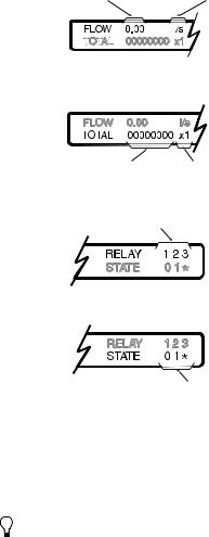
The normal display during operation is the Flow and Total Display (F2).
flow rate field |
relay / "no echo" field |
totalizer field |
status field |
7ML19985AB01 |
OCM III |
28 |
Flow Rate Field
flow rate |
units, P5 |
||||||||
|
|
|
|
|
|
|
|
|
|
|
|
|
|
|
|
|
|
|
|
|
|
|
|
|
|
|
|
|
|
|
|
|
|
|
|
|
|
|
|
Totalizer Field
total |
multiplier, P32 |
Relay / No Echo Field
relay identification
under loss of echo condition, "NO ECHO" will alternately flash
Status Field
relay status : 0 = relay de-energized 1 = relay energized
* = alarm state (indicated when flashing)
The OCM-3 provides illumination for the LCD for easier viewing of the display. Illumination can be set (P14) to be normally on or off, or automatic. When automatic is selected, the lighting will automatically go on when keypad activity is sensed and then extinguish after 15 seconds of inactivity.
For battery operation, set display lighting to off or auto.
DAMPING
The OCM-3 provides two separate damping functions: reading and mA output. Zero or no damping allows fastest response while high or 100% provides the slowest response. The damping is usually set to provide a reliable response without sacrificing stability.
The reading damping, P13, dampens only the flow rate reading of the ‘Flow and Total’ display F2. The damping selections are: off, low, medium and high. Relay functions associated with flow rate respond to the dampened reading values.
mA output damping, P27, dampens the change in the mA output. The parameter entry is in seconds for spanning the 0 to 100% of the mA range selected (P26). Displays and relay functions associated with the mA output respond to its
dampened value.
7ML19985AB01 |
OCM III |
29 |

RELAYS
Three on board multipurpose relays are provided by the OCM-3. P15, 18 and 21 set the respective functions for relays 1, 2 and 3. Depending on the function selected, these parameters determine the need and configuration of the subsequent relay control parameters, P16, 17 (relay 1); P19, 20 (relay 2) and P22, 23 (relay 3).
If the relay is to function as a driver for a remote totalizer or as a flow sampler contact, the totalizer multiplier (P32) will be factored by the setpoint . Note that parameters P16, P19, and P22 will default to zero. When a relay is set to totalizer (P32), you must have the applicable parameter (P16 for relay 1, P19 for relay 2, or P22 for relay 3) set to something other than zero (normally 1).
Example: For relay 1
Relay totalizer factor = totalizer factor (P32) relay 1 setpoint (P16)
=100 (P32=5)
2 (P16)
=50 units/pulse
The status of each relay is shown in the display. Refer to \ Flow and Total Display.
For battery operation, have relays energizing on alarm.
mA OUTPUT
The OCM-3 provides a mA output (TB1-4/5) which can be assigned (P24) to represent the measurement of flow, head, velocity or temperature. The associated scaling, P25, is factory set to a value of ‘0’. This provides normal scaling with respect to the assigned measurement.
Normal scaling for representation of flow, head or velocity is:
» 0 or 4 mA |
= 0 |
|
» 20 mA |
= maximum measurement value for: |
» P6*: flow rate |
|
|
at maximum head |
|
|
» P7: maximum head |
|
|
» P10: velocity |
|
|
at maximum head |
Normal scaling for representation of temperature is:
» 0 or 4 mA = – 40 °C
» 20 mA = 60 °C
If custom scaling is required, the 20 mA corresponding value (other than 0) can be entered into P25. The range (0 to 20 or 4 to 20 mA) and damping (see Damping) are set via P26 and P27 respectively.
7ML19985AB01 |
OCM III |
30 |
 Loading...