


SINAUT MD740-1
User Manual

!Safety precautions
General: The product SINAUT MD740-1 complies with European standard EN60950, 05.2003, Safety of Information Technology Equipment.
Read the installation instructions carefully before using the device. Keep the device away from children, especially small children.
The device must not be installed or operated outdoors or at damp locations.
Do not operate the device if the connecting leads or the device itself are damaged.
External power supply: Use only an external power supply which complies with IEC/EN60950 chapter 2.5 “Limited power sources” and UL1310 / NEC Class 2 respectively. The output voltage of the external power supply must not exceed 30VDC. The output of the external power supply must be short-circuit proof.
Warning
The power supply unit to supply the SINAUT MD740-1 must comply with NEC Class 2 circuits as outlined in the National Electrical Code (ANSI/NFPA 70) only
When connecting to a battery or accumulator, make sure that an all-pole circuit-breaker (main battery switch) with sufficient selectivity and a fuse with sufficient selectivity are provided between the device and the battery or accumulator.
Please pay regard to section Technical Data of the installation manual, as well as the installation and utilisation regulations of the respective manufacturers of the power supply, the battery or the accumulator.
Digital gate input: Make sure that the specified input voltage range is observed. Please pay regard to sections Connecting the device and Technical Data of this documentation.
Digital gate output: Switching voltage and switching current must not exceed the specified maximum values. Please pay regard to sections Connecting the device and Technical Data of this documentation.
SIM card: To install the SIM card the device must be opened. Before opening the device, disconnect it from the supply voltage. Static charges can damage the device when it is open. Discharge the electric static of your body before opening the device. To do so, touch an earthed surface, e.g. the metal casing of the switch cabinet. Please pay regard to section Inserting or changing the SIM card of the installation manual.
Handling cables: Never pull a cable connector out of a socket by its cable, but pull on the connector itself. Cable connectors with screw fasteners (D-Sub) must always be screwed on tightly. Do not lay the cable over sharp corners and edges without edge protection. If necessary, provide sufficient strain relief for the cables.
For safety reasons, make sure that the bending radius of the cables is observed.
Failure to observe the bending radius of the antenna cable results in the deterioration of the system's transmission and reception properties. The minimum bending radius static must not fall below 5 times the cable diameter and dynamic below 15 times the cable diameter.
Radio device: Never use the device in places where the operation of radio devices is prohibited. The device contains a radio transmitter which could in certain circumstances impair the functionality of electronic medical devices such as hearing aids or pacemakers. You can obtain advice from your physician or the manufacturer of such devices. To prevent data carriers from being demagnetised, do not keep disks, credit cards or other magnetic data carriers near the device.
2 von 105 |
SINAUT MD740-1 |

Antenna: Use only the antenna of the SINAUT TELECONTROL accessory program being released for the SINAUT MD740-1. Other antennas may cause damages and the device will loose official approvals like FCC.
Installing antennas: The emission limits as recommended by the Commission on Radiological Protection (13/14 September 2001) must be observed.
Installing an external antenna: When installing an antenna outdoors it is essential that the antenna is fitted correctly by a qualified person. Lightning Protection Standard VDE V 0185 Sections 1 to 4, in its current version, and further standards must be observed.
Lightning protection category for buildings: For outdoor installation, the antenna may be fitted only within the lightning protection zones O/E or 1. These lightning protection zones are prescribed by the lightning protection spherical radius.
The EMV lightning protection zone concept is to be observed. To avoid large induction loops a lightning protection equipotential bonding is to be used. If the antenna or antenna cable is installed near to the lightning protection system, the minimum distances to the lightning protection system must be observed. If this is not possible, insulated installation as described in VDE V 0185 Sections 1 to 4, in its current version, is essential.
FCC Part 15
This equipment has been tested and found to comply with the limits for a Class A digital device, pursuant to Part 15 of the FCC Rules. These limits are designed to provide reasonable protection against harmful interference in a residential installation. This equipment generates, uses and can radiate radio frequency energy and, if not installed and used in accordance with the instructions, may cause harmful interference to radio communications. However, there is no guarantee that interference will not occur in a particular installation. If this equipment does cause harmful interference to radio or television reception, which can be determined by turning the equipment off and on, the user is encouraged to try to correct the interference by one or more of the following measures:
•Reorient or relocate the receiving antenna.
•Increase the separation between the equipment and receiver.
•Connect the equipment into an outlet on a circuit different from that to which the receiver is connected.
•Consult the dealer / installer or an experienced radio/TV technician for help.
This device contains 900 MHz GSM and 1800 DCS functions that are not operational in U.S. territories.
FCC Part 15.19
This device complies with Part 15 of the FCC Rules. Operation is subject to the following two conditions:
1.this device may not cause harmful interference, and
2.this device must accept any interference received, including interference that may cause undesired operation.
FCC Part 15.21
Modifications not expressly approved by this company could void the user's authority to operate the equipment.
SINAUT MD740-1 |
3 von 105 |
Installation by qualified personnel only
You may only use the SINAUT MD720-3 with an antenna of the SINAUT MD720-3 accessory program.
The installation of the SINAUT MD720-3 and the antenna as well as servicing is to be performed by qualified technical personnel only. When servicing the antenna, or working at distances closer than those listed below, ensure the transmitter has been disabled.
RF Exposure mobile
Warning !
!Typically, the antenna connected to the transmitter is an omni-directional antenna with 0dB gain. Using this antenna the total composite power in PCS mode is smaller than 1 watt ERP.
The internal / external antennas used for this mobile transmitter must provide a separation distance of at least 20 cm from all persons and must not be co-located or operating in conjunction with any other antenna or transmitter."
!Warning !
This is a class A equipment. This equipment can disturb other electric equipment in living areas; in this case the operator can be demanded to carry out appropriate measures.
!Warning !
Please note that data packets exchanged for setting up connections, reconnecting, connect attempts (e.g. Server switched off, wrong destination address, etc.) as well as keeping the connection alive are also subject to charge.
Product no. |
3155 |
Doc. no. |
3155AD001 Rev. 1.1 |
4 von 105 |
SINAUT MD740-1 |

|
|
|
Contents |
|
|
Contents |
|
1 |
Introduction ......................................................................................................... |
7 |
|
|
1.1 |
To be able to use the SINAUT MD740-1... ........................................ |
9 |
|
1.2 |
IP address of the remote site............................................................. |
9 |
2 The LEDs of the SINAUT MD740-1 ................................................................... |
10 |
||
|
|
S (Status), Q (Quality), C (Connect) ................................................ |
10 |
|
|
DC5V, STAT, LINL, VPN ................................................................. |
11 |
3 Putting the device into operation..................................................................... |
12 |
||
|
3.1 |
Connecting the device ..................................................................... |
12 |
|
|
Switching the device on/off .............................................................. |
13 |
|
3.2 |
Configuring the PIN ......................................................................... |
14 |
|
3.3 |
Inserting or changing the SIM card.................................................. |
15 |
4 |
Configuration..................................................................................................... |
19 |
|
|
|
Remote configuration....................................................................... |
19 |
|
|
Prerequisites for local configuration................................................. |
19 |
|
|
TCP/IP configuration of the network adapter ................................... |
19 |
|
|
Establish configuration connection .................................................. |
20 |
|
|
Perform configuration ...................................................................... |
23 |
|
4.1 |
Network menu ................................................................................. |
24 |
|
4.2 |
Firewall menu .................................................................................. |
27 |
|
4.3 |
VPN menu ....................................................................................... |
36 |
|
4.4 |
Services menu................................................................................. |
54 |
|
4.5 |
Access menu ................................................................................... |
62 |
|
4.6 |
Features menu................................................................................. |
68 |
|
4.7 |
Support menu .................................................................................. |
72 |
|
4.8 |
System menu................................................................................... |
75 |
|
4.9 |
CIDR (Classless InterDomain Routing) ........................................... |
79 |
|
4.10 |
Network example diagram ............................................................... |
81 |
5 Integrated website showing device and connection data.............................. |
83 |
||
|
5.1 |
Accessing the Web server locally via the service interface.............. |
83 |
|
|
Via dial-up connection: .................................................................... |
83 |
|
|
Installing the modem for access to the service interface ................. |
83 |
|
|
Creating the dial-up connection for the service interface................. |
84 |
|
|
Making a connection to the SINAUT MD740-1 website................... |
85 |
|
|
Closing the service connection ........................................................ |
85 |
|
5.2 |
Accessing the Web server locally via the application interface |
|
|
|
(10/100 BASE-T connector)............................................................. |
86 |
|
|
Prerequisites.................................................................................... |
86 |
|
|
Making a connection to the SINAUT MD740-1 website................... |
86 |
|
5.3 |
Accessing the Web Server of the SINAUT MD740-1 from a remote |
|
|
|
computer via the GPRS network...................................................... |
87 |
|
|
Prerequisites.................................................................................... |
87 |
|
|
Making a connection to the SINAUT MD740-1 website................... |
87 |
|
5.4 |
The website of the SINAUT MD740-1.............................................. |
88 |
|
|
Device Information page.................................................................. |
89 |
SINAUT MD740-1 |
5 von 105 |

Contents
|
Session Statistics and Total Statistics pages................................... |
90 |
|
PPP layer (PPP - Point-to-Point-Protocol) ....................................... |
90 |
|
IP layer (IP - Internet Protocol) ........................................................ |
91 |
|
Status Information page................................................................... |
92 |
6 Firmware update via the integrated FTP server.............................................. |
93 |
|
7 |
Glossary 94 |
|
|
AES ................................................................................................. |
94 |
|
APN (Access Point Name)............................................................... |
94 |
|
Asymmetrical encryption.................................................................. |
95 |
|
DynDNS provider............................................................................. |
95 |
|
TCP/IP (Transmission Control Protocol/Internet Protocol)............... |
96 |
|
Service Provider .............................................................................. |
96 |
|
Protocol, transmission protocol........................................................ |
97 |
|
Client / Server.................................................................................. |
97 |
|
PPPoE ............................................................................................. |
97 |
|
PPTP ............................................................................................... |
97 |
|
VPN (Virtual Private Network) ......................................................... |
97 |
|
DES / 3DES..................................................................................... |
98 |
|
Private Key, Public key; Certification (X.509) .................................. |
98 |
|
NAT (Network Address Translation) ................................................ |
99 |
|
Datagram......................................................................................... |
99 |
|
IPSec ............................................................................................. |
100 |
|
Spoofing, anti-spoofing .................................................................. |
100 |
|
Symmetrical encryption ................................................................. |
100 |
|
Port number................................................................................... |
100 |
|
IP address ..................................................................................... |
101 |
|
X.509 Certificate ............................................................................ |
102 |
8 |
Technical Data................................................................................................. |
103 |
|
Pin assignment interface Service................................................... |
104 |
|
Pin assignment interface 10/100 BASE-T...................................... |
104 |
6 von 105 |
SINAUT MD740-1 |

Introduction
1 Introduction
The SINAUT MD740-1 serves the following purpose:
The device establishes secure IP data connections by radio
•via the GPRS (General Packet Radio Service) of a GSM network (Global System for Mobile Communication = mobile radio network).
•GPRS modem
•VPN router
•Firewall
To do so, the device combines the following functions:
•GPRS modem for flexible data communication via GPRS
•VPN router for secure data transfer via public networks (IPSec protocol, 3DES data encryption, AES encryption)
•Firewall for protection against unauthorised access. The dynamic packet filter inspects data packets using the source and destination address (stateful packet inspection) and blocks unwanted data traffic (anti-spoofing).
The device is configured simply using a Web browser.
VPN features |
• |
Protocol: IPsec (tunnel and transport mode) |
|
• IPsec DES encryption at 56 Bit |
|
|
• IPsec 3DES encryption at 168 Bit |
|
|
• IPsec AES encryption at 128, 192 and 256 Bit |
|
|
• Packet authentication: MD5, SHA-1 |
|
|
• Internet Key Exchange (IKE) with Main and Quick Mode |
|
|
• Authentication: Pre-Shared Key (PSK), X.509v3 certificates |
|
|
• |
DynDNS |
|
• |
NAT-T |
|
• Dead Peer Detection (DPD) |
|
Firewall features |
• |
Stateful Packet Inspection |
|
• |
Anti-spoofing |
|
• |
NAT (IP Masquerading) |
|
• |
Port Forwarding |
Other features |
• |
DNS Cache |
|
• |
DHCP Server |
|
• |
NTP |
|
• |
Remote Logging |
SINAUT MD740-1 |
7 von 105 |

Introduction
Scenario 1:
Dedicated line to GPRS or Internet (with fixed, known IP address)
|
GPRS |
Internet |
|
|
|
|
|
|
|
Firewall |
LAN |
|
|
|
|
Application TAINY |
IPSec tunnel |
|
|
GMOD-V2-IO |
|
Router with |
|
|
|
Firewall |
Server in |
|
|
|
company |
|
|
|
network |
The application is connected locally direct to the SINAUT MD740-1: e.g. statement printer, notebook or PC. This application uses the SINAUT MD740-1 in order to have secure access to a remote LAN as if it were connected direct to the LAN.
The remote site is a computer in a corporate network. The network, protected by a VPN router with firewall, is connected to the GPRS network or the Internet and has a known or definable IP address.
Scenario 2:
GPRS
LAN
|
|
|
|
|
|
|
|
|
|
|
|
TAINY GMOD-V2-IO |
|
|
|
|
|
|
|
TAINY |
|
IPSec tunnel |
|
|
|
Application |
|
|
||||||||||
|
|
|
||||||||||
|
|
|
|
|
|
|
GMOD-V2-IO |
|
|
|
|
|
Server in company network
The remote site is another SINAUT MD740-1.
! |
The direct connection of two GPRS end devices is not technically supported in |
all GSM/GPRS networks. |
8 von 105 |
SINAUT MD740-1 |

Introduction
1.1To be able to use the SINAUT MD740-1...
you require... |
• a subscriber contract with a GSM network operator (e.g. TD1, |
|
Vodafone, E-Plus, O2) that supports GPRS |
•release of the GPRS for the user in question by the network operator
1.2IP address of the remote site
In order that a SINAUT MD740-1 can actively establish a VPN connection the remote site must have a fixed IP address (an IP address consists of a maximum of 4 numbers, separated by dots, which can each have up to three digits, e.g. 255.122.201.005). With many Internet Service Providers (ISPs), however, the IP addresses are assigned dynamically, i.e. the IP addresses of the computers or networks which have access to the Internet change. There are 3 ways of obtaining a fixed IP address:
Fixed IP address via |
The communication partner is connected to the GPRS network |
dedicated line to |
via a leased dedicated line. In this case it has normally been |
GPRS |
assigned a fixed IP address by the network operator. |
Fixed IP address via |
The communication partner can be accessed via the Internet and |
Internet service |
has been assigned a fixed IP address by the Internet service |
provider |
provider (the address can be applied for from some Internet |
|
service providers). |
Fixed IP address via |
To solve the problem of dynamic IP address assignment, |
DynDNS service |
DynDNS services can be used. With this kind of service, the |
|
SINAUT MD740-1, for example, or the remote computer, |
|
regardless of the dynamic IP address it currently possesses, is |
|
accessible via a fixed domain name. Each time the IP address |
|
changes, the SINAUT MD740-1 or the remote computer reports |
|
the new IP address to the DynDNS server, so that the current IP |
|
address is always assigned to the domain name on the DNS |
|
server - see glossary, page 95. |
|
The use of a DynDNS service requires a contract with the |
|
provider concerned, e.g. DynDNS.org or DNS4BIZ.com. |
SINAUT MD740-1 |
9 von 105 |
The LEDs of the SINAUT MD740-1
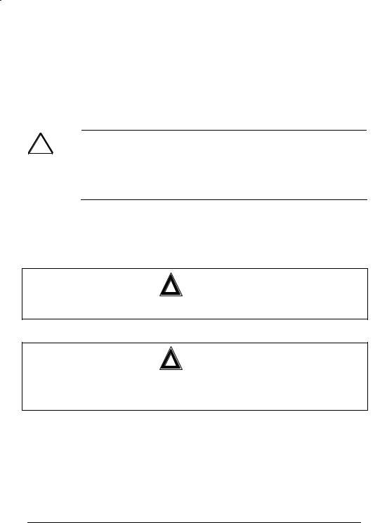
2 The LEDs of the SINAUT MD740-1
LEDs
Power
Status
LEDs |
|
LAN |
VPN
S (Status)
Q (Quality)
C (Connect)
S (Status), Q (Quality), C (Connect)
LED |
Status |
Meaning |
S, Q, C |
Fast lighting in sequence |
Boot procedure |
in sequence |
Slowly lighting in sequence |
Update* |
|
Synchronous fast blinking |
Error |
S (Status) |
Blinks slowly |
Device waiting for PIN input |
|
Blinks fast |
PIN error / SIM error |
|
OFF |
No GPRS attach |
|
ON |
GPRS attach |
Q (Quality) |
Blinks slowly |
Booking into the GPRS network |
|
1 x intermittent blinking |
Field strength not sufficient or unknown** |
|
2 x intermittent blinking |
Field strength sufficient |
|
3 x intermittent blinking |
Field strength medium |
|
ON always |
Field strength high |
|
OFF |
Waiting for PIN input |
C (Connect) |
OFF |
No connection |
|
ON |
Connection to server/remote station |
|
|
GPRS: Authentication on and IP |
|
|
allocation from network successful |
*When updating the communication firmware, at first the LEDs are slowly blinking in sequence. Further in the process only the LED S is On.
**Shortly after booking into the GSM network, the quality LED blinks once, thus signalling the field strength as not sufficient or unknown. Cause: At this stage the device can only register availability
10 von 105 |
SINAUT MD740-1 |
The LEDs of the SINAUT MD740-1
of signal, but not the signal quality. The field strength is then requested in a next check, 15 seconds later.
DC5V, STAT, LINL, VPN
LED |
Colour |
Status |
Meaning |
DC5V |
Green |
ON |
Device switched on, operating voltage is on |
|
|
OFF |
Device switched off, no operating voltage |
STAT |
Yellow |
Blinking |
IOVPN board operational |
LINK |
Yellow |
ON |
Ethernet connection to local PC / LAN |
|
|
|
established |
|
|
OFF |
No Ethernet connection to local PC / LAN |
VPN |
Yellow |
ON |
VPN tunnel established* |
|
|
OFF |
VPN-Tunnel not established |
*Shortly after switching on of the SINAUT MD740-1, the LED VPN is set to on for a short period of time although the VPN tunnel has not yet been established. Cause: self-test of the components during starting procedure of the device.
SINAUT MD740-1 |
11 von 105 |
Putting the device into operation
3 Putting the device into operation
To put the device into operation, perform the following steps in the order given:
|
|
Page |
1. |
Connect the device |
12 |
2. |
Configure the PIN |
14 |
3. |
Insert or change the SIM card |
15 |
4. |
Perform further configuration |
19 |
!First tell the device the PIN of the SIM card. Then insert the SIM card.
!The device also supports SIM cards without a PIN. If your SIM card has no PIN you can also insert the SIM card before performing configuration.
!The device must be switched off when you insert or remove the SIM card.
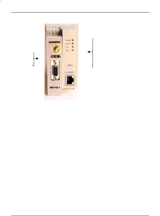
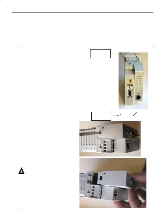
3.1Connecting the device
Current supply: The screw terminals on top of the device for connecting of the current supply: 24 V DC voltage (nominal), max. 600mA
+ 24 V + 24 V
0 V
0 V
Both terminal screws to the left (24 V) are connected.
Both terminal screws to the right (0 V) are connected.
Service interface. Optional:
For the connection of a PC to display device, status and connection information.
To connect, use a V.24 cable.
Digital gate input |
I1+ |
|
I1- |
|
|
Antenna
(approx. 50 Ohm)
Application interface.
Connect the application device here.
When connecting to the network card of a computer use a crossover Ethernet cable.
When connecting to the network use a UTP cable (CAT 5).
Digital gate output
O1a
O1b
12 von 105 |
SINAUT MD740-1 |

Putting the device into operation
Switching the device on/off
The SINAUT MD740-1 switches on as soon as the operating voltage is supplied (see Connecting the device, page 12).
The devices switches off when disconnected from the supply voltage.
When switching on When the device is switched on the POWER LED comes on first. If the device has a valid configuration and the SIM card is inserted the device automatically books into the GPRS network. When the CONNECT LED comes on a GPRS connection has been established.
The device is designed in such a way that it can be left switched on permanently.
SINAUT MD740-1 |
13 von 105 |
Putting the device into operation
3.2Configuring the PIN
In order for the SINAUT MD740-1 to be able to communicate via the GPRS network of your network operator you must tell the device the PIN (Personal Identification Number) of the SIM card. Then you can insert the SIM card into the device.
The device also supports SIM cards without a PIN. If your SIM card has no PIN it is not necessary to configure the PIN. You can then insert the SIM card immediately.
To configure the PIN, proceed as follows:
1.Using your Web browser (e.g. MS Internet Explorer), establish a configuration connection with the SINAUT MD740-1.
To do this, follow the description in section 4 Configuration, page 19 to 23.
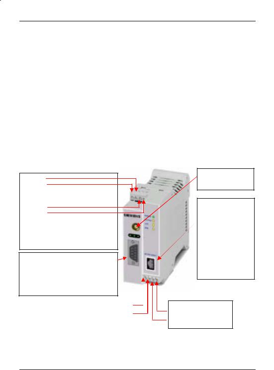
2.When the Administrator website of the SINAUT MD740-1 appears, select Network # GPRS.
Enter PIN
(in both fields)
In the PIN field, enter the PIN of the SIM card that you then want to insert into the device.
! Enter the same PIN in both fields. Then click on OK or Apply.
Once the PIN is set, the message "Not configured yet" is no longer displayed.
3. You can close the connection by closing the Web browser.
14 von 105 |
SINAUT MD740-1 |
Putting the device into operation
3.3Inserting or changing the SIM card
!SINAUT MD740-1 must be switched off when you insert or change the SIM card
!A plug-in SIM card (3 Volt) is used.
1.Make sure that the device is disconnected from the supply voltage.
2.The SINAUT MD740-1 must be
opened to insert the SIM card. |
Clamps |
The housing is fastened with clamps, |
|
two each on top of the housing and on |
|
the bottom side. |
|
Clamps
3.Release the two clamps on the housing part with antenna socket.
For this purpose, press the clamps cautiously with a suitable object (see picture) so that catch opens.
4.Cautiously pull the unlocked housing part so that the housing opens.
!The boards in both front housing parts are connected by an IO cable. When opening the housing make sure that the cable connection is not loosened or damaged. If necessary, unlock both front housing parts and cautiously pull them out together.
SINAUT MD740-1 |
15 von 105 |

Putting the device into operation
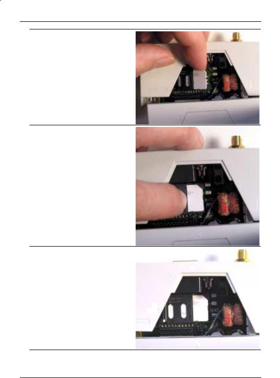
5.The SIM card holder is visible on the motherboard.
SIM card holder
6.With a suitable object open the flap of the SIM card holder by moving it cautiously about 2mm to the left – in the direction of the arrow (see red arrow in the illustration) so that it can be raised.
7.Raise the flap of the SIM card holder so that you can insert the SIM card.
In the illustration below, the compartment into which you can insert the SIM card is emphasized in white.
16 von 105 |
SINAUT MD740-1 |
Putting the device into operation
8.Slide the SIM card into the flap of the SIM card holder, with the goldcoloured microchip pointing down. The flap has a groove for this purpose. The notched corner of the SIM card has to point towards the front of the device (see illustration).
9.Slide the SIM card down into the flap as far as possible.
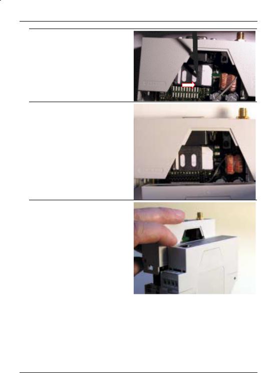
10.Lower the flap paying attention to the notched corner of the SIM card (see illustration).
SINAUT MD740-1 |
17 von 105 |
Putting the device into operation
11.With your fingernail or a suitable object move the flap about 2 mm to the right (in the direction of the arrow) until you can feel it click into place.
12.Now the SIM card holder is locked into position.
13.Check the connection of the internal IO connection cable.
Finally re-attach both housing parts: Slide the motherboard into the rails on top and bottom inside the rear section of the housing. Close the housing by slightly pressing the housing parts together so that the clamps on the upper and lower parts of the housing engage.
The housing is locked when all clamps have clicked shut.
18 von 105 |
SINAUT MD740-1 |

|
Configuration |
4 Configuration |
|
Remote |
! Remote configuration is possible only if the SINAUT MD740-1 is |
configuration |
configured for remote access (see page 64). In this case, |
|
proceed exactly as described as from section Establish |
|
configuration connection, page 20. |
Prerequisites for |
• The computer with which you are performing the configuration |
local configuration |
must either |
- be connected direct to the Ethernet socket of the SINAUT MD740-1 via cross-over network cable
- or it must have direct access via LAN to the SINAUT MD740-1.
• The SINAUT MD740-1 must be switched on.
• The network adapter of the computer with which you are performing configuration must have the following TCP/IP configuration:
IP address: 192.168.1.2 Subnet mask: 255.255.255.0
Default gateway: 192.168.1.1
Preferred DNS server: address of the Domain Name Server
TCP/IP configuration of the network adapter
…under Windows XP
TCP/IP configuration of the network adapter under Windows XP:
1.Click on Start, Settings, Control Panel, Network Connections: right-click on the icon for LAN adapter and click on Properties in the context menu.
On the General tab in the Properties of LAN connection local network dialogue box, select the Internet Protocol (TCP/IP) entry and then click on the
Properties button to make the following dialogue box appear:
SINAUT MD740-1 |
19 von 105 |

Configuration
2. Enter the following:
|
|
IP address: 192.168.1.2 |
|
|
Subnet mask: 255.255.255.0 |
|
|
Default gateway: 192.168.1.1 |
|
|
Preferred DNS server: address of the Domain Name Server |
|
|
|
…under |
|
|
Windows |
2000 |
Under Windows 2000, proceed accordingly. |
!
Preferred DNS server
If you call up addresses via a domain name (e.g. www.neuhaus.de), a Domain Name Server (DNS) has to look up which IP address belongs to the name. You can determine the following as the Domain Name Server:
•the DNS address of the network operator
OR
•the local IP address of the SINAUT MD740-1, provided that it is configured to resolve hostnames in IP addresses, see
Services menu.
To determine the Domain Name Server in the TCP/IP configuration of your network adapter, proceed as described above.
Establish |
Proceed as follows: |
configuration |
1. Start a Web browser. |
connection |
(e.g. MS Internet Explorer from Version 5.0 or Netscape Communicator |
|
from Version 4.0; the Web browser must support SSL (i.e. https)) |
IP address of the SINAUT MD740-1:
https://192.168.1.1
2.Make sure that the browser does not automatically dial up a connection when starting.
In MS Internet Explorer you make this setting as follows: menu
Tools, Internet Options..., Connections tab: under Dial-up and Virtual Private Network settings, Never dial a connection must be activated.
3.In the address line of the browser, enter the full address of the SINAUT MD740-1. In accordance with the default setting, this is:
https://192.168.1.1
Consequence: the security alert shown on the next page appears.
20 von 105 |
SINAUT MD740-1 |
Configuration
! In case the Administrator website does not appear...
If the browser still tells you after several attempts that the page cannot be displayed, try the following:
•Check the hardware connection.
To do so on a Windows computer, enter the following command via the DOS prompt (menu Start, Programs, Tools, Command Prompt):
ping 192.168.1.1
If there is no message about the reception of the 4 sent packets within the prescribed time, check the cable, the connections and the network card.
•Make sure that the browser does not use a proxy server.
In MS Internet Explorer (Version 6.0) you make this setting as follows: menu Tools, Internet Options..., Connections tab: under LAN Settings click on the Settings button, in the
Settings for local area network (LAN) dialogue box make sure that the Use a proxy server for your LAN entry is not activated.
•If there are other LAN connections active on the computer, deactivate them for the duration of configuration.
Under Windows menu Start, Settings, Control Panel, Network Connections / Network and Dial-up Connections right-click on the appropriate icon and select Deactivate in the context menu.
•Enter the address of the SINAUT MD740-1 plus slash: https://192.168.1.1/
SINAUT MD740-1 |
21 von 105 |
Configuration
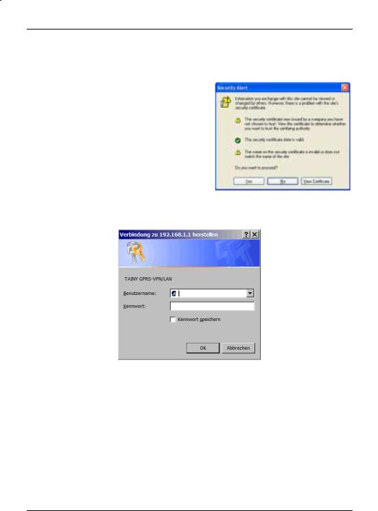
When the |
4. Following the successful establishment of the connection the |
connection is |
following security alert appears: |
successfully |
|
established... |
|
|
Explanation: |
|
As the device can only be |
|
administered via |
|
encrypted accesses it is |
|
supplied with a self-signed |
|
certificate. |
Acknowledge the security alert with Yes.
5. You are prompted to enter the user name and the password.
The default setting is:
User name: |
admin |
Password: |
tainy |
Start page of the 6. Consequence: the Administrator website of the Administrator SINAUT MD740-1 appears - see next page. website
22 von 105 |
SINAUT MD740-1 |

Configuration
|
To perform the configuration, proceed as follows: |
|
Perform |
1. |
Call up the |
configuration |
|
required setting |
|
|
area via the menu. |
|
2. |
Make the required |
|
|
entries on the page |
|
|
concerned. |
|
3. |
Confirm with OK or |
|
|
Apply, so that the |
settings are accepted by the device.
If a page is not up to date when next displayed because the browser is loading it from the cache, refresh the page display. To do so, click on the Refresh icon in the browser's icon bar.
!Depending on how you configure the SINAUT MD740-1, you may then have to adapt the network interface of the connected computer or network accordingly.
!When entering IP addresses, always enter the IP address sub-numbers without the leading zeros, e.g.: 192.168.0.8.
Please note:
In the following screenshots of the configuration pages of the SINAUT MD740-1 are displayed. The caption of these screenshots refers to another product from SIEMENS A&D. This product basically supports the same features as SINAUT MD740-1 (VPN, Firewall) but has a different housing.
SINAUT MD740-1 |
23 von 105 |
Configuration
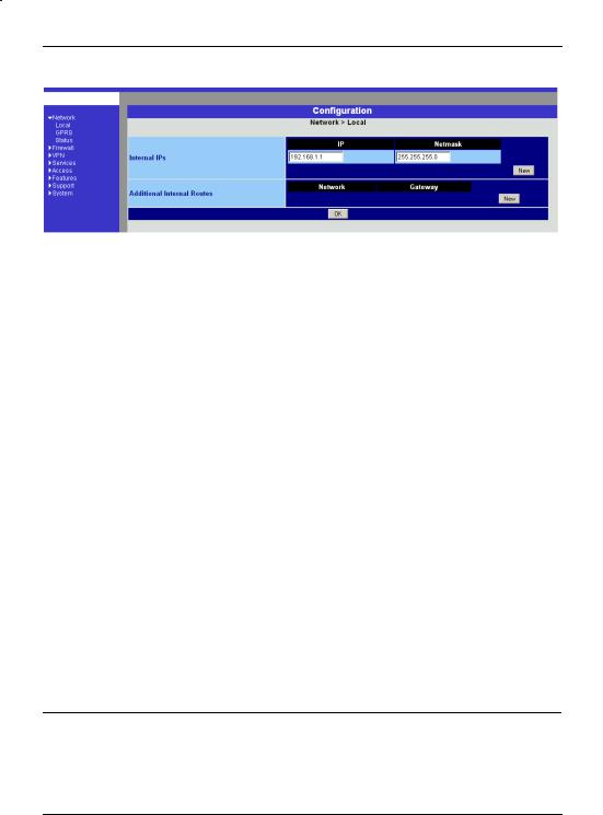
4.1Network menu
Network # Local
Local IP address of the SINAUT MD740- 1 according to default setting:
192.168.1.1
Internal IPs
An internal IP is the IP address at which the SINAUT MD740-1 can be accessed by devices of the locally connected network.
The default setting for the IP address is as follows:
IP address: |
192.168.1.1 |
Local netmask: |
255.255.255.0 |
You can determine further addresses at which the
SINAUT MD740-1 can be accessed by devices of the locally connected network. This is helpful if, for example, the locally connected network is divided into subnets. In this case, several devices from different subnets access the
SINAUT MD740-1 at different addresses.
!If you want to determine a further internal IP, click on New. You can determine any number of internal IPs.
!If you want to delete an internal IP, click on Delete. (The first IP address in the list cannot be deleted.)
Additional Internal Routes
If further subnets are connected to the locally connected network, you can define additional routes.
See also Network example diagram, page 81.
!If you want to determine a further route to a subnet, click on
New.
Enter the following:
-the IP address of the subnet (network), and
-the IP address of the gateway via which the subnet is connected.
You can determine any number of internal routes.
! If you want to delete an internal route, click on Delete.
24 von 105 |
SINAUT MD740-1 |
Configuration
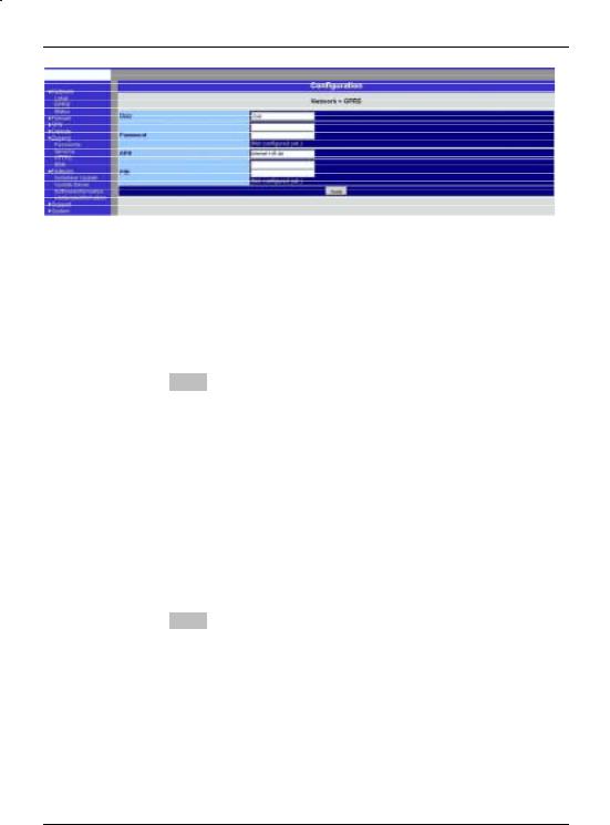
Network # GPRS
User (user name)
Password
When the SINAUT MD740-1 logs into the GPRS network it is generally asked for the user name and the password before it is given access to the network.
Some GSM/GPRS network operators dispense with access control via user name and/or password. In this case, enter visitor in the appropriate field.
INFO: Documentation from your network operator.
! Enter the password identically in both fields.
Once the password has been set, the message "Not configured yet" is no longer displayed.
APN (Access Point Name)
This denotes the gateway
-to the Internet. In this case the remote site can be reached via the Internet.
OR
-to the private network. In this case the remote site is connected to the GPRS network operator via a leased dedicated line.
INFO:
•Internet APN:
You will find the APN in the documentation or at the website of your GSM/GPRS network operator, or you can call the hotline and ask for it there.
•Private APN:
You can obtain the access data from your network operator.
SINAUT MD740-1 |
25 von 105 |
Configuration
When putting the device into operation:
1.Tell the device the PIN of the SIM card
2.Insert the SIM card
PIN of the SIM card inserted in the device
In order for the SINAUT MD740-1 to be able to operate with the SIM card of your network operator you must tell the device the PIN (Personal Identification Number) of the SIM card, provided that the SIM card has a PIN. Only after this should you insert the SIM card into the switched off(!) device.
To do so, enter the PIN and click on OK or Apply.
If a PIN has been set, the message "Not configured yet" is no longer displayed.
!Enter the PIN identically in both fields.
!The entered PIN must tally with the PIN of the SIM card with which the device is to operate.
!You cannot change the PIN of the SIM card with this device.
Confirm the entries on this configuration page by clicking on OK or
Apply.
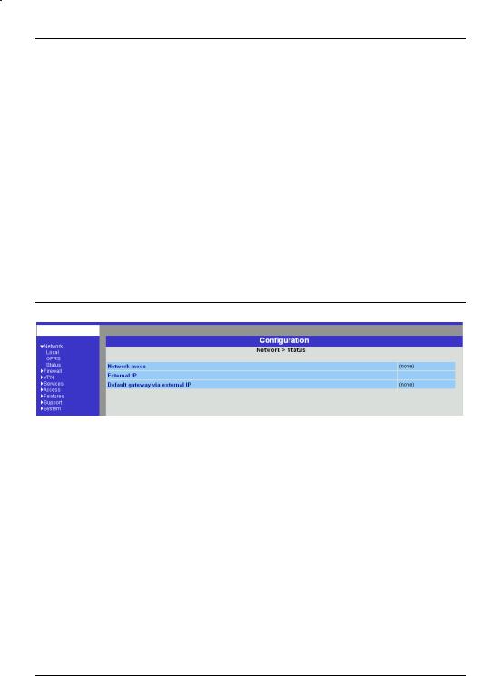
Network # Status
Display only: |
Network mode |
|
This indicates whether a GPRS connection has been |
|
established (display: "modem connected") or whether the |
|
GPRS modem is on standby and ready to establish a GPRS |
|
connection (display: "(none)” or “modem (later)"). |
External IP /GPRS:
The IP address at which the device can be reached from the outside. This IP address is assigned to the device by the operator of the GPRS network for the current connection.
Default gateway via external IP:
IP address of the integrated GPRS module.
26 von 105 |
SINAUT MD740-1 |
Configuration
4.2Firewall menu
The SINAUT MD740-1 comes with a Stateful Packet Inspection Firewall. The connection data of an active connection are collected in a database (connection tracking). This means that rules are only to be defined for one direction, while data from the other direction of a connection, and only these, are allowed through automatically. A side effect of this is that existing connections are not interrupted as a result of reconfiguration, even if a corresponding new connection should no longer be established.
Default firewall setting:
•All incoming connections are rejected (except VPN).
•The data packets of all outgoing connections are rejected (except VPN and except connections to the integrated website which provides information about devices and connection data).
!VPN connections are not subject to the firewall rules determined under this menu item. You can determine firewall rules for each individual VPN connection under the menu VPN # Connections.
!If several firewall rules have been set, they are scanned in the order of the entries from top to bottom until a suitable rule is found. This rule is then applied. Should there also be rules further down in the list which would be also suitable, they are ignored.
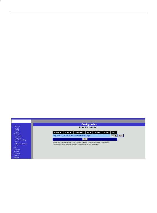
Firewall # Incoming
This lists the fixed firewall rules. These apply to incoming data connections which have been initiated externally.
•If no rule has been set, all incoming connections (except VPN) are rejected (= default setting).
Deleting a rule
Click on Delete next to the entry concerned. Then click on OK or Apply.
SINAUT MD740-1 |
27 von 105 |

Configuration
Setting a new rule
If you want to set a new rule, click on New.
Set the required rule (see below), then click on OK or Apply. You receive a system message as confirmation.
You can make the following possible entries:
Protocol: All means: TCP, UDP, ICMP and others.
IP address: 0.0.0.0/0 means all addresses. To denote a range, use CIDR syntax - see CIDR (Classless InterDomain Routing), page 79.
Port:
(is evaluated only with TCP and UDP protocols) any means any port.
startport:endport (e.g. 110:120) denotes the port area.
Individual ports can be entered either with the port number or with the corresponding service name: (e.g. 110 for pop3 or pop3 for 110).
Action:
Accept means that the data packets may pass.
Refuse means that the data packets are turned away so that the sender is informed of the refusal.
Reject means that data packets are not allowed to pass. They are "swallowed" so that the sender is not informed of their whereabouts.
Log:
For each individual firewall rule you can determine whether, when the rule is applied,
-the event is to be logged - set Log to Yes
-or not - set Log to No (default setting)
Log entries for unknown connection attempts:
This logs all connection attempts which are not recorded by the prevalent rules.
28 von 105 |
SINAUT MD740-1 |
Configuration
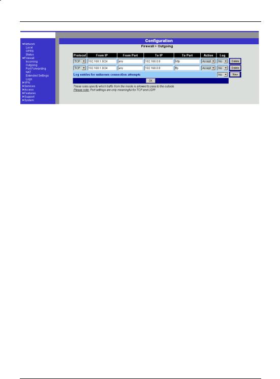
Firewall # Outgoing
This lists the fixed firewall rules. These apply to outgoing data packets which belong to GPRS connections initiated by the SINAUT MD740-1 to communicate with a remote site.
!If no rule is set, all outgoing connections are prohibited (except VPN).
!Default setting: outgoing connections prohibited (except VPN and connections to the integrated website which provides information about devices and connection data).
Deleting a rule
Click on Delete next to the entry concerned. Then click on OK or Apply.
Setting a new rule
If you want to set a new rule, click on New.
Set the required rule (see below), then click on OK or Apply. You receive a system message as confirmation.
You can make the following possible entries:
Protocol: All means: TCP, UDP, ICMP and others.
IP address: 0.0.0.0/0 means all addresses. To denote a range, use CIDR syntax - see CIDR (Classless InterDomain Routing), page 79.
Port:
(is only evaluated with TCP and UDP protocols) any means any port.
startport:endport (e.g. 110:120) denotes the port area.
Individual ports can be entered either with the port number or with the corresponding service name: (e.g. 110 for pop3 or pop3 for 110).
Action:
Accept means that the data packets may pass.
Refuse means that the data packets are turned away so that the
SINAUT MD740-1 |
29 von 105 |
Configuration
sender is informed of the refusal.
Reject means that data packets are not allowed to pass. They are swallowed so that the sender is not informed of their whereabouts.
Log:
For each individual firewall rule you can determine whether, when the rule is applied,
-the event is to be logged - set Log to Yes
-or not - set Log to No (default setting)
Log entries for unknown connection attempts:
This logs all connection attempts which are not recorded by the prevalent rules.
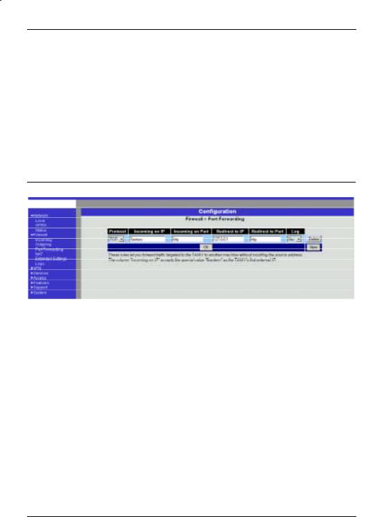
Firewall #Port Forwarding
This lists the fixed rules for port forwarding.
With port forwarding the following takes place: the header of incoming data packets from the external network which are intended for the external IP address (or one of the external IP addresses) of the SINAUT MD740-1 and for a particular port of the SINAUT MD740-1 are rewritten in such a way that they are forwarded to the internal network to a particular computer and to a particular port of this computer. That means that the IP address and port number in the headers of incoming data packets are changed.
This method is also called Destination NAT.
!The rules set here take priority over the settings under Firewall
# Incoming.
Deleting a rule
Click on Delete next to the entry concerned. Then click on OK or Apply.
Setting a new rule
30 von 105 |
SINAUT MD740-1 |
 Loading...