


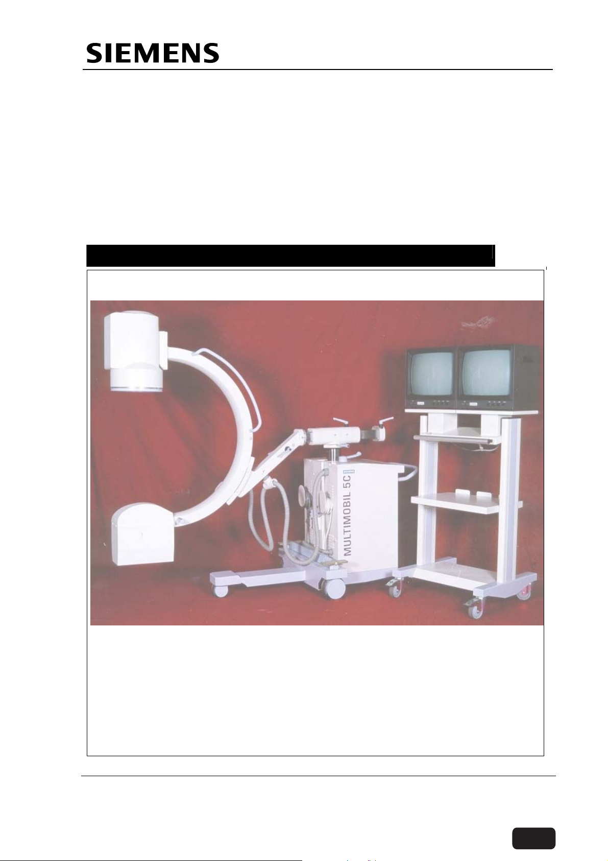
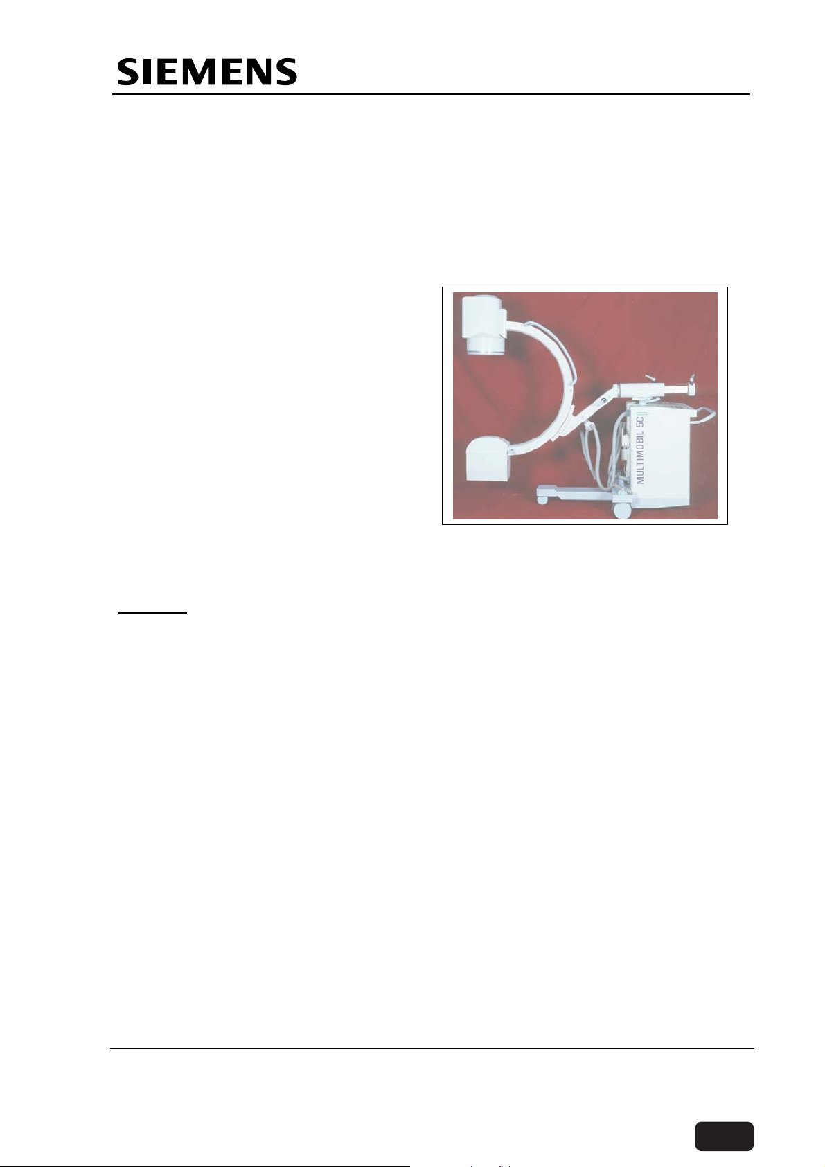
Multimobil 5C
Table of contents
 Loading...
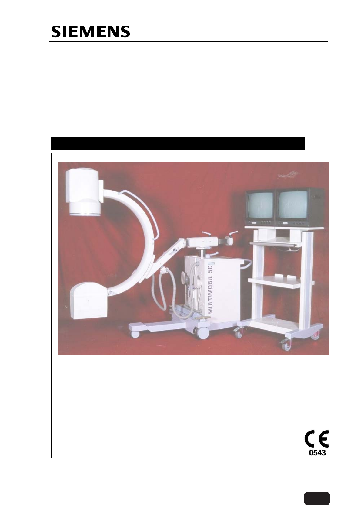
Multimobil 5C
Med
SERVICE MANUAL
Version 2.0
Copyright © SIEMENS LTD. Med INDIA
The information in this CD is not a controlled document and to be used only for reference.
Before ordering any parts HO-Med-CS-SP to be contacted for obtaining the latest information.
Back
5605
5422040
001/002/003/004
Prepared by
Multimobil 5C
Multimobil 5C
Service Manual
Med
Service Manual
Version: 2.0
Status: Released
Copyright SIEMENS LTD.,Med INDIA
Name: Mahadevan.J
Dept: GW/Engg
Signature:
Date:09.06.2004
Siemens Ltd. Med India
Mahadevan.J
The information in this CD is not a controlled document and to be used only for reference.
Before ordering any parts HO-Med-CS-SP to be contacted for obtaining the latest information.
DMR 4.10
SPU Number
Item Number
Version
Reviewed by Released by
Name: H.S.Usgaonkar
Dept: GW/Engg
Signature:
Date: 09.06.2004
Version 2.0 Released
Copyright SIEMENS LTD. All rights reserved. For internal use only
Name:V.P.Khandeparker
Dept: GW/Q
Signature:
Date: 09.06.2004
Page 1 of 2
Back

Multimobil 5C
Service Manual
1 History
1.1 Alteration History
Version Date Prepared by / Dept. CCI NO. Change and Reason for
change
01 11.07.2003 S.K.Kutty GW/SP ---- First Release
2.0 09.06.2004 Mahadevan.J
GW/Engg
6148 Upgrade w.r to 110V and
60Hz requirements & common
manual for all versions of the
product.
Siemens Ltd. Med India
Mahadevan.J
The information in this CD is not a controlled document and to be used only for reference.
Before ordering any parts HO-Med-CS-SP to be contacted for obtaining the latest information.
Copyright SIEMENS LTD. All rights reserved. For internal use only
Version 2.0 Released
Page 2 of 2
Back

Main Index
Multimobil 5C
Service Manual
5422040 002
1 Pre-installation
2 Installation Instructions
3 Service Instructions
4 Wiring Diagrams
5 Wiring Description
6 Circuit Description
Siemens Ltd. Med India Version 2.0 Pages 1 of 1
7 Circuit Diagrams
The information in this CD is not a controlled document and to be used only for reference.
Before ordering any parts HO-Med-CS-SP to be contacted for obtaining the latest information.
Copyright © SIEMENS LTD. All rights reserved. For internal use only
Back
Pre-installation Instructions
Multimobil 5C
Med
Pre-installation
Version 2.0
Siemens Ltd. Med India Version 2.0 Page 1 of 10
The information in this CD is not a controlled document and to be used only for reference.
Before ordering any parts HO-Med-CS-SP to be contacted for obtaining the latest information.
Copyright © SIEMENS LTD.,Med INDIA
Copyright © SIEMENS LTD. All rights reserved. For internal use only
Back

Pre-installation Instructions
INDEX
1 PRE-INSTALLATION...................................................................................................................3
1.1 TECHNICAL SPECIFICATIONS .......................................................................................................3
1.2 INFORMATION ON ROOM PLANNING..............................................................................................6
1.3 PACKAGING................................................................................................................................6
1.4 UNLOADING................................................................................................................................7
1.5 UNPACKING THE MM5C..............................................................................................................8
1.6 UNPACKING THE MONITOR TROLLEY.............................................................................................9
1.7 INSTALLATION OF THE MONITORS ...............................................................................................9
Siemens Ltd. Med India Version 2.0 Page 2 of 10
Copyright © SIEMENS LTD. All rights reserved. For internal use only
The information in this CD is not a controlled document and to be used only for reference.
Before ordering any parts HO-Med-CS-SP to be contacted for obtaining the latest information.
Back
Pre-installation Instructions
1 Pre-installation
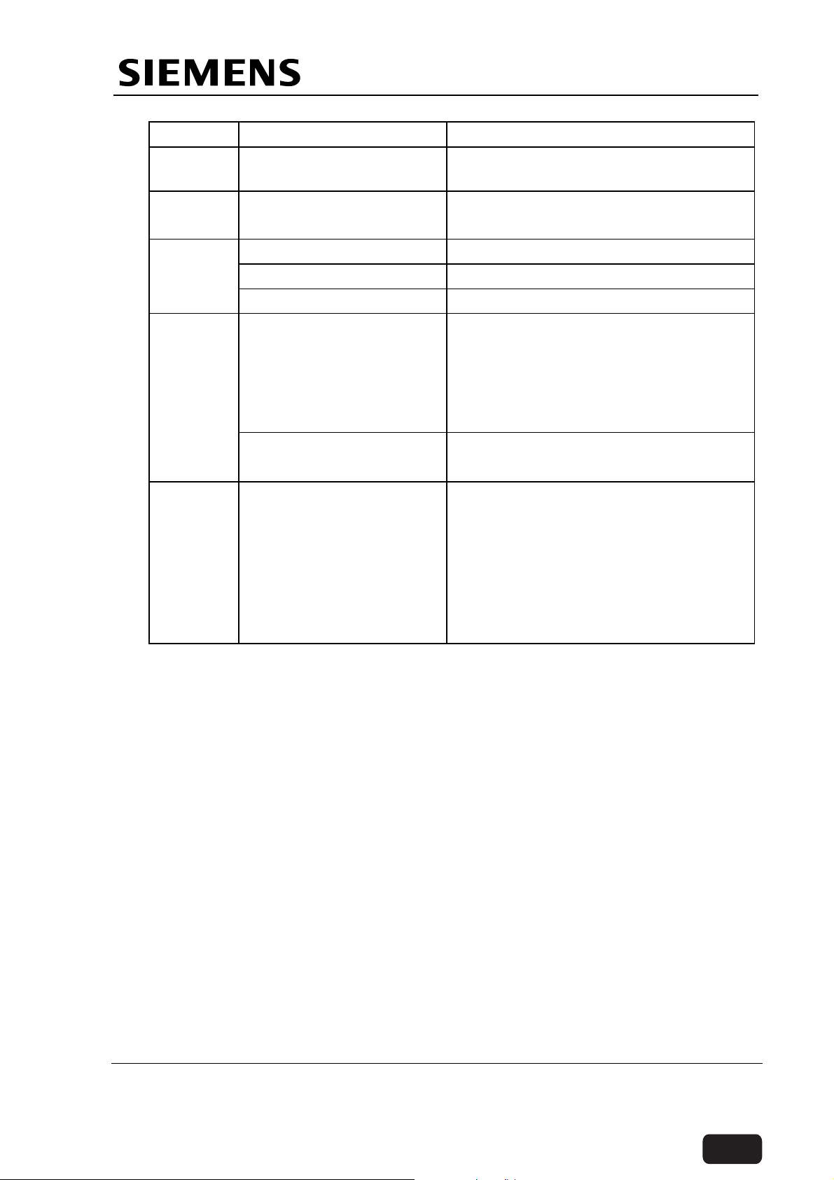
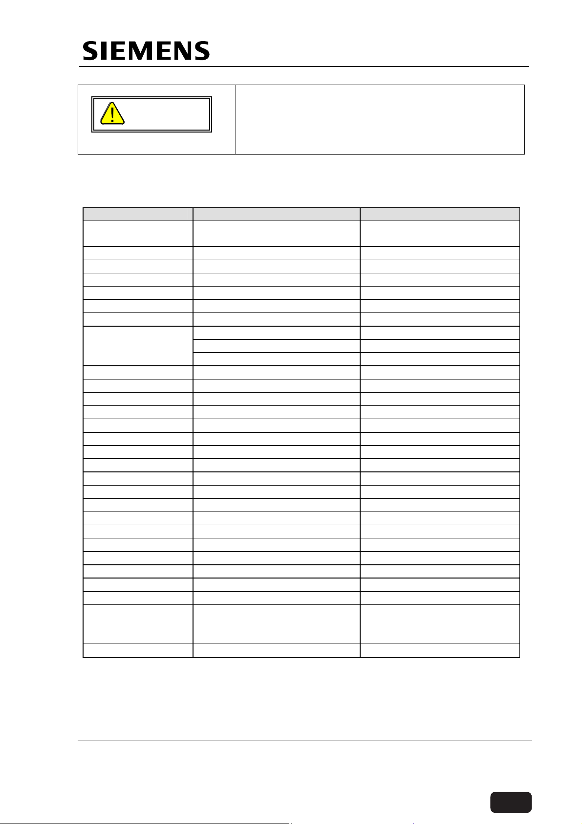
1.1 Technical Specifications
Sr.No Parameter Value
1. Mains Voltage
110V/190 -240V∼
2. Line frequency 50 / 60Hz
3. Line impedance
1.5 Ω (max) @ 190-240 V
0.36Ω (max) @ 110V
4. Length of power cable 5 m
5. Power Output –
Radiography
2.5 kW (100 kV, 25 mA) @ 190-240V
1.6KW (100 kV, 16 mA) @110V
Nominal Electric power at
100kV and 100mSec.
6. Wave Shape Multipulse DC - Ripple 5kV max
7. KVp Range 40 – 100kV in 20 steps
8. KV Accuracy
9. mA-range
≤ ± 5 %
13 – 63 mA @ 190-240V input
10 – 40 mA @ 110V input
10. mAs Range
0.32 – 200mAs at 40kV
0.32 – 160mAs at 42 - 50kV
0.32 – 125mAs at 52 - 63kV
0.32 – 100mAs at 66 - 77kV
0.32 – 80 mAs at 81 - 100kV
11. mAs Accuracy
≤ 10 % + 0.2 mAsfor mAs ≤ 20 mAs
≤ 5 % + 0.2 mAs for mAs > 20 mAs
12. Exposure Time 20mSec - 5 Sec in 24 steps @190240V
20mSec – 8 Sec in 26 steps @ 110V
For details of kV, mA and exposure
time combinations as per EN 60601-27 refer to exposure chart on page 6-14.
13. Fluoroscopy voltage 40-110 kV
14. Fluoroscopy Modes ADR(Automatic dosage regulation):
Anti-isowatt & Contrast.
15. Fluroscopy mA range Anti-isowatt 0.5 to 5 mA
16. Fluroscopy Power 550W continous
Contrast 0.5 to 7mA
17. Timer Fluoroscopy time display with timer
Siemens Ltd. Med India Version 2.0 Page 3 of 10
Copyright © SIEMENS LTD. All rights reserved. For internal use only
The information in this CD is not a controlled document and to be used only for reference.
Before ordering any parts HO-Med-CS-SP to be contacted for obtaining the latest information.
Back

Pre-installation Instructions
Sr.No Parameter Value
reset and 5 minute buzzer indication
18. Thermal Protection Auto cutoff of fluoroscopy and
radiography in case of tube head
temperature exceeding 60°(+ 5°)
celcius
19. Power Input:
Continous
Instantaneous
20. Mains Isolation
External: done by the
user
21. Type and degree of
1.5kVA
3.5kVA
Power supply cord shall be plugged
where both poles (L & N) are isolated
simaltaneously.
Class – I, Type B equipment
protection against electric
shock (EN 60601 – 1)
22. X - ray Tube Stationary Anode DF-151R
23. Focal Spot – nominal
value
0.5 for Fluoroscopy
1.5 for radiography
24. Inherent tube Filtration 0.8 mm Al at 50kV
25. Nominal kV 110 kV
26. Target Angle
16°
27. Collimator Motorised, multileaf Iris Collimator
28. Total filtration 5.3 mm Al at 100kV
29. Exposure release Switch 2 Step
30. Exposure Rate for
Radiography
Pulse to pause ratio 1:30; corresponds
to a cool down period of 4 minutes at
maximum output.
31. Max. X-ray coverage 430X430mm at SID 909 mm
32. Mode of Operation Continuous operation
33. Focus-II distance 860mm for 9“ system
900mm for 6“ system
34. Max. cassette size at 900
10“X12“
cm SID
35. Grid Circular grid placed at the input of the
II tube , 40 Ip/cm, 8:1
36. Image Intensifier 9“ / 6“
37. Image Intensifier tube
resolution
Nominal 52lp/cm and zoom 68 Ip/cm
for 9“ system
Nominal 66 lp/cm and zoom 77 Ip/cm
38. Nominal entrance field 230mm for 9“ system
Siemens Ltd. Med India Version 2.0 Page 4 of 10
Copyright © SIEMENS LTD. All rights reserved. For internal use only
The information in this CD is not a controlled document and to be used only for reference.
Before ordering any parts HO-Med-CS-SP to be contacted for obtaining the latest information.
Back

Pre-installation Instructions
Sr.No Parameter Value
150mm for 6“ system
39. II output image size
diameter
25±0.5mm for 9“ system
20±0.5mm for 6“ system
40. Zoom (field size) 230mm/160mm for 9“ system
150 mm/100 mm for 6“ system
41. TV camera
AC100∼220V±10%
Input Voltage
42. Pick Up device
Pick UP area
CCD
6.4X4.8mm
43. Effective Pixels 752(H)X582(V)(CCIR)
768(H)X494(V)(EIA)
44. TV System 625lines/50Hz(CCIR)
525lines/60Hz(EIA)
45. No. of monitors 2 monitors one each for Live/Last
Image Hold(LIH) and stored memory
display
46. Monitor size 17“monochrome with 9“ system and
15“ monochrome with 6“ system
47. Monitor screen High brightness,high resolution with
independent brightness and contrast
control
48. TV standard CCIR 625 lines at 50 Hz
49. Aspect ratio 4:3
50. Image rotation Endless clockwise and anti-clockwise
wih complete 360°rotation in 10sec
51. Recursive filter Steps of 1,1.5,2,3,4,8,10,12,14,
16,24&32 to minimize dynamic blur
52. Image reversal Left/right and top/bottom
53. II Chain Resolution Nominal 1.2 lp/cm Zoom 1.6 lp/cm for
9” system
Nominal 1.4 lp/cm Zoom 2.0 lp/cm for
6” system
54. C-arm orbital movement
55. Angulation
125°(+90°to -35°)
±190°
56. Horizontal travel 200mm
57. Swivel range
58. Vertical travel 400 mm
±12.5°
59. Mobility Directional lock on rear wheels
enabling excellent manuerability
Siemens Ltd. Med India Version 2.0 Page 5 of 10
Copyright © SIEMENS LTD. All rights reserved. For internal use only
The information in this CD is not a controlled document and to be used only for reference.
Before ordering any parts HO-Med-CS-SP to be contacted for obtaining the latest information.
Back
Pre-installation Instructions
Sr.No Parameter Value
60. Max. floor incline for
transport
61. Mechanical Dimensions
(lxbxh)
62.
Weight
Without packing 280kg
With packing 680kg
63.
Environmental conditions
Transport and Storage
Temp range.
Relative Humidity range
Atmospheric pressure
Operating Temperature
Relative Humidity range
64. Conformance to
Standards
5°
2000 x 800 x1720 mm (min)
2070x1050 x2120 mm (max)
-15° C to 45° C
Upto 90%
50 kpa to 106 kpa
10° C to 40° C
Upto 85% non condensing
EN 60601-1:1990
EN 60601-2-7:1998
EN 60601-1-3:1994
EN 60601-1-2:2001
Compliance to AERB Type Approval
Ceritification
Compliance to BIS test certification.
1.2 Information on Room Planning
No specific conditions required. Following are the recommended room conditions for
proper functioning of the unit.
Ambient Temperature (Room temperature): + 40 °C Max
Air Humidity: up to 75%, Non-condensing.
During Transport and storage of the product the ambient temperature should not be
below -15°C or rise above +45°C. Storage is permissible in rooms with minimum
amount of dust and Humidity in range of 30% to 95% RH provided no condensation
occurs.
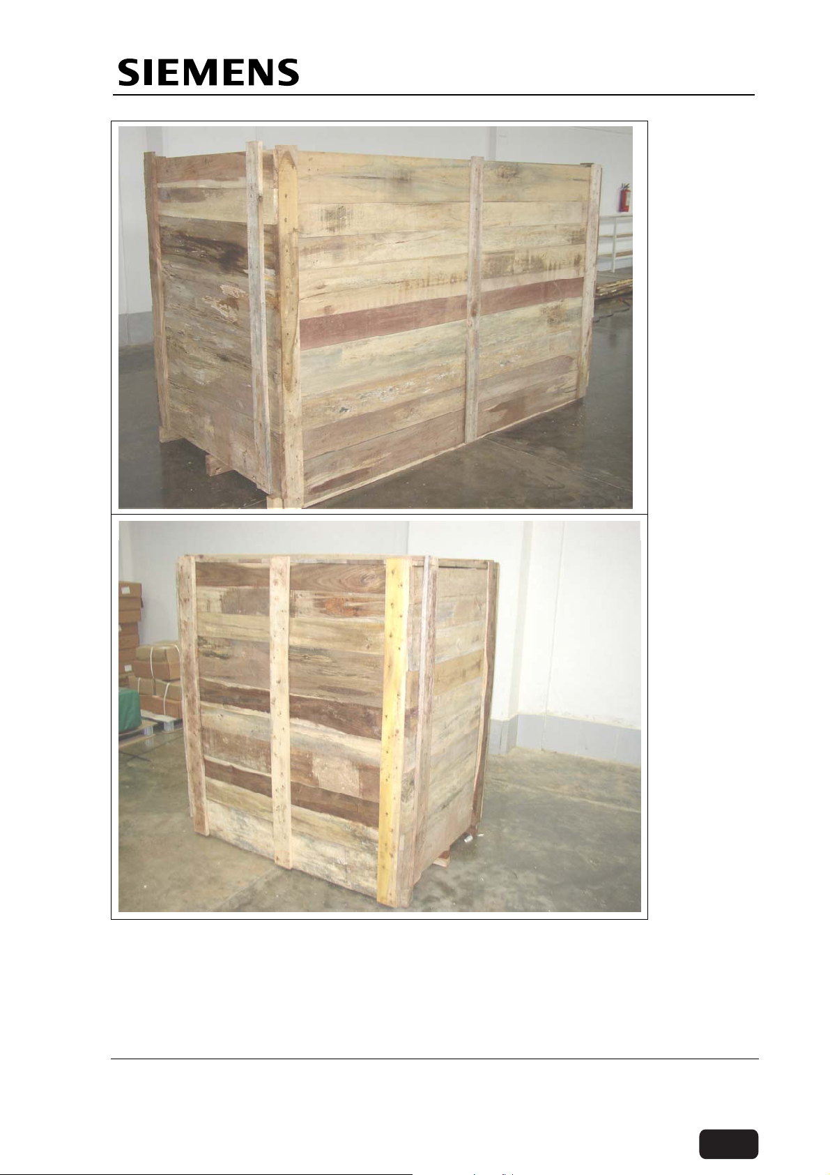
1.3 Packaging
The Multimobil 5C unit is delivered in two wooden boxes.
One box consists of the Monitor trolley. This is a wooden box with the trolley mounted
on the wooden base and is fixed using clamping brackets.
The second box contains the MM5C unit along with monitors and accessories .The Carm unit is clamped using brackets on the wooden base. The two monitors are packed
in the corrugated box and placed on the wooden platform.
One box consists of standard accessories i.e. sterile cloth, Clips and user manual.
Siemens Ltd. Med India Version 2.0 Page 6 of 10
Copyright © SIEMENS LTD. All rights reserved. For internal use only
The information in this CD is not a controlled document and to be used only for reference.
Before ordering any parts HO-Med-CS-SP to be contacted for obtaining the latest information.
Back
Pre-installation Instructions
MM5C with
monitors and
accessories
Monitor trolley
for MM5C
1.4 Unloading
The unloading of the unit from the truck can be carried out using any of the following
ways depending on the site conditions:
1) Using a forklift.
2) Using an overhead travelling crane.
3) Using a chain pulley block and tripod.
Siemens Ltd. Med India Version 2.0 Page 7 of 10
Copyright © SIEMENS LTD. All rights reserved. For internal use only
The information in this CD is not a controlled document and to be used only for reference.
Before ordering any parts HO-Med-CS-SP to be contacted for obtaining the latest information.
Back

Pre-installation Instructions
4) Using conventional ways i.e. Using wedges, wooden planks, pipes or rods and
labour etc.
Note: 1. All boxes are provided with transport base.
2. Do not roll the boxes.
3. Do not drop the boxes from a height of more than 20cms.
4. Observe the stickers
(This side up) and (handle with care) on the
Packing for proper handling.
Once the unit is removed from the transport, place it on the ground on the base.
1.5 Unpacking the MM5C
The complete system must be inspected for physical damage and / or material
short-fall and factory must be informed accordingly.
The Multimobil 5C consists of fragile components like camera, Image intensifier, X-ray
Tube etc. Sufficient care must be taken while unloading / Unpacking the unit.
Refer the
unpacking instructions provided on the packing.
Observe the following steps:
1) Remove the restraining strips by cutting it. Use a cutting plier for this purpose.
2) Start removing the wooden planks. For this purpose the service engineer should use
a claw hammer or nail pulling plier and preferably a crow bar.
3) First of all remove the top planks. Upon opening this plank you will be able to see the
unit inside. Ensure that the unit has not received any transit damages.
4) Now, remove the front and rear wall of the box one by one. The front wall is provided
with a ramp. Hence, place this plank carefully for pushing the unit out of the platform.
5) Now you will see three wooden blocks fixed across the unit for supporting the wall
and also to support the image intensifier and single tank.This are supporting beams.
6) Loosen these blocks from one side and remove them gently.Now, remove the side
walls.
7) Care should be taken to see that the wooden planks or the nails do not damage the
unit.
8) Now, you can easily remove the ESD bags.
9) After removing the ESD bags, remove the monitor boxes and accessories and take
them to the OT.
10) Remove the packing strips and thermocol packing from the control, II and single
tank. Also, remove the wooden lever fixed at the base by cutting the strap.
11) Next step is to remove the clamping brackets. First of all, remove the bracket used
for clamping the single tank and Image intensifier. Secondly, remove the bracket
used to clamp C-arm. Third, remove the brackets on the rear wheels. Next remove
the brackets used to clamp the base.
12) Now ensure that the rear wheels are in locked condition. Also the C-Arm should be
in locked condition.
13) Remove the bolts of the clamping brackets at the rear side on which the housing is
resting. Now, using the lever, gently lift the base along the bracket so that the rubber
block can be removed. Once the rubber blocks are removed, remove the clamping
bracket.
14) Now, remove the two brackets on the front end of the base. Lift from sides using
wooden lever. Remove the rubber buffer and remove the bracket.
Siemens Ltd. Med India Version 2.0 Page 8 of 10
Copyright © SIEMENS LTD. All rights reserved. For internal use only
The information in this CD is not a controlled document and to be used only for reference.
Before ordering any parts HO-Med-CS-SP to be contacted for obtaining the latest information.
Back
Pre-installation Instructions
15) Now the unit will be resting on the wooden platform. Release the brakes and push
the unit down to the ground through the ramp.
DO NOT HOLD THE UNIT AT POINTS
WARNING
MARKED
WHILE LIFTING
Observe the following steps for transporting the unit to the OT.
Unlock the C-arm and turn it to the position shown in the figure and lock it. This is
the suitable position for moving the unit from the platform.
Now , release the brake of the C-Arm and swing the C-Arm back to the normal position
as shown in the figure for transportation. This is also the parking position.
Roll all the cables and hang it on the cable holder provided on the housing.
Unbrake the wheels and move the unit to the OT. Use the steering for easy
manouverabilty.
1.6 Unpacking the monitor trolley
Observe the following steps:
1) Remove the restraining strips by cutting it .Use a cutting plier for this purpose.
2) Remove the top plank.
3) Remove the front and rear wall of the box.
4) Remove the supporting beams fixed across the sidewalls.
5) Remove the side planks. The trolley is mounted on the clamping brackets.
6) Remove the ESD bag.
7) Now, using a spanner of 16-17, remove the clamping brackets.
8) Lift the trolley gently by holding at the base and supporting it from top. Place it on the
floor.
9) Release the brakes and the trolley can be shifted to the OT.
1.7 Installation Of The Monitors
1) Open the corrugated box and remove the monitors.
2) Open the accessories box and remove the packet of hardware.
Siemens Ltd. Med India Version 2.0 Page 9 of 10
Copyright © SIEMENS LTD. All rights reserved. For internal use only
The information in this CD is not a controlled document and to be used only for reference.
Before ordering any parts HO-Med-CS-SP to be contacted for obtaining the latest information.
Back
Pre-installation Instructions
3) Place the monitors on the top tray of the monitor trolley and fasten them using
socket HD screw M4x20, spring washer and plain washers.
4) Make use of the connector provided on the monitor trolley for providing power supply
to the monitors.
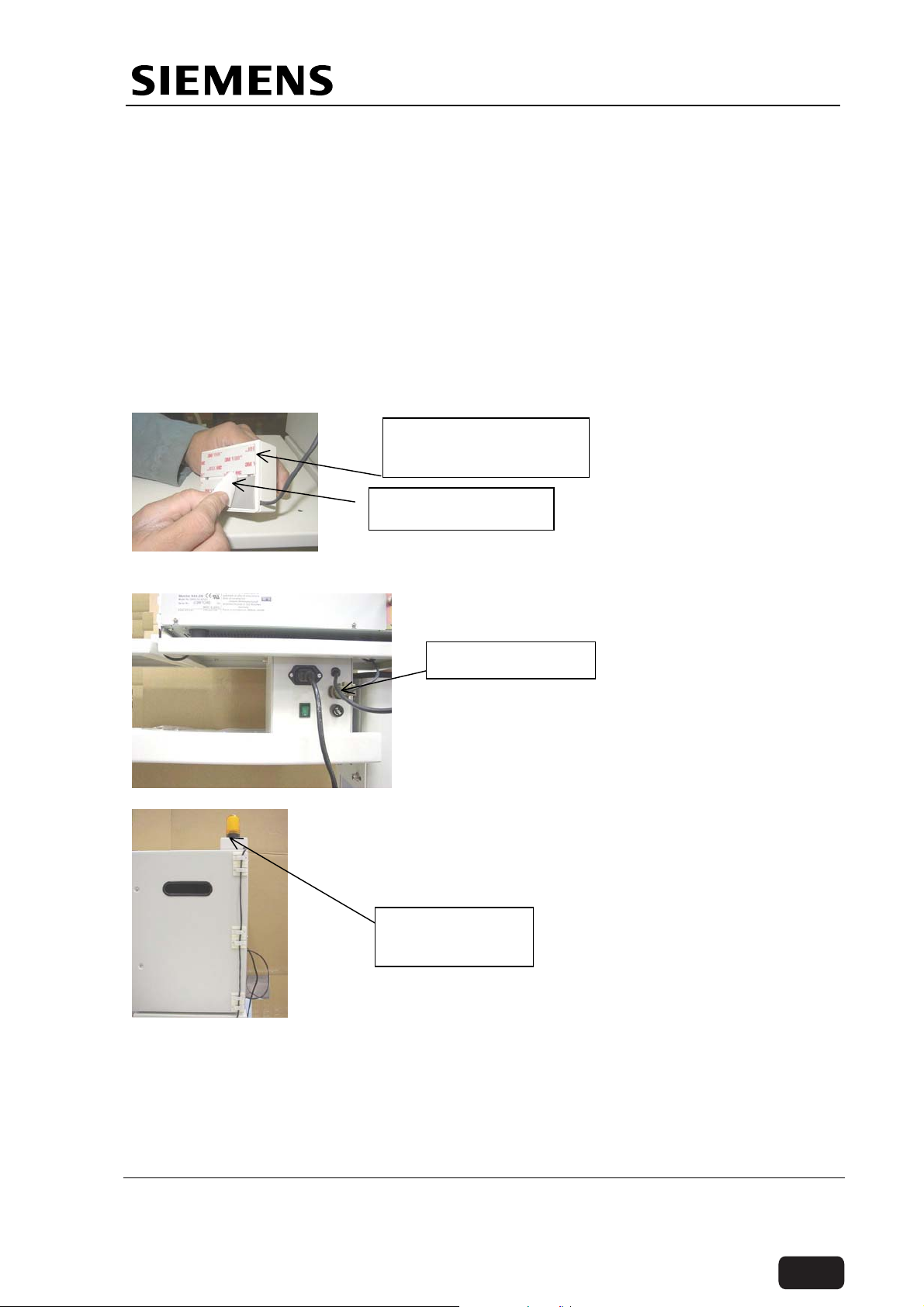
5) Install the radiation indication lamp as explained below.
The Radiation Indication lamp assembly has been packed along with the
monitor.
Unpack the monitors and remove the radiation indication lamp assembly.
Fix the monitor having clamps on it for cable routing, on to the left side monitor
tray using hardwares provided in the accessories box.
Peel off the protection layer of the double-sided tape and fix the radiationindicating lamp on top of this monitor.
Radiation indication
lamp assembly
Double sided Tape
Route the cables through the clamps and Connect the male part of allied
connector to the female part fixed on the monitor trolley.
Allied connector
Route the cable in between the monitors.
Radiation
indication lamp
Siemens Ltd. Med India Version 2.0 Page 10 of 10
Copyright © SIEMENS LTD. All rights reserved. For internal use only
The information in this CD is not a controlled document and to be used only for reference.
Before ordering any parts HO-Med-CS-SP to be contacted for obtaining the latest information.
Back

Multimobil 5C
Installation Instructions
Med
Installation Instructions
Version 2.0
Siemens Ltd. Med India Version 2.0
The information in this CD is not a controlled document and to be used only for reference.
Before ordering any parts HO-Med-CS-SP to be contacted for obtaining the latest information.
Copyright © SIEMENS LTD.,Med INDIA
Copyright © SIEMENS LTD. All rights reserved. For internal use only
Page 1 of 9
Back

Installation Instructions
INDEX
1 INSTALLATION ...........................................................................................................................3
1.1 TRANSPORT POSITION OF UNIT ...................................................................................................3
1.2 SAFETY INFORMATION.................................................................................................................3
1.2.1 General ................................................................................................................................3
1.2.2 Safety Checks......................................................................................................................4
1.2.3 Overload Protection.............................................................................................................4
1.2.4 Radiation Protection.............................................................................................................5
1.3 PRELIMINARY CHECKS ................................................................................................................5
1.3.1 Mechanical Check................................................................................................................5
1.3.2 Electrical Check...................................................................................................................5
1.3.3 Collimator.............................................................................................................................7
1.3.4 Exposure..............................................................................................................................8
1.4 GENERAL CHECK........................................................................................................................9
Siemens Ltd. Med India Version 2.0
Page 2 of 9
Copyright © SIEMENS LTD. All rights reserved. For internal use only
The information in this CD is not a controlled document and to be used only for reference.
Before ordering any parts HO-Med-CS-SP to be contacted for obtaining the latest information.
Back
Installation Instructions
1 Installation
1.1 Transport Position of Unit
After unpacking the unit as explained in pre installation, bring the unit to its transport
position as explained below.
• Adjust the column to the bottom most
position.
• Bring the holder and C-Arm in the
default transport setting and lock all
the levers.
• Hang all the cables on the cable
winder. Place the foot switch in the
holder.
• Loosen the foot brake.
• Pay attention that the wheels do not
strike against any obstacles.
• For transport of monitor trolley,
loosen the brakes.
• For more details Refer Operational
Manual.
• Label is provided on the unit showing
the transport position.
NOTE: While transporting the unit on
the slope ensure that the slope should
not exceed +10°.If the slope is more
than 10°,there is a risk of toppling.
1.2 Safety Information
1.2.1 General
It shall be the duty of the installation personnel and the user to ensure that all the
safety measures concerning the unit operation and installation are adhered to.
The unit must be checked for the status of its safety measures at least every year or
any time desired by the user, not exceeding one year.
However, we recommend in the interest of the safety of the patient, the user, and
other personnel to have a yearly drill on operational safety.
If there are any special regulations of the hospital/institute, to be followed over and
above the general safety regulations pertaining to the installation, the same must be
ensured.
Siemens Ltd. Med India Version 2.0
Page 3 of 9
Copyright © SIEMENS LTD. All rights reserved. For internal use only
The information in this CD is not a controlled document and to be used only for reference.
Before ordering any parts HO-Med-CS-SP to be contacted for obtaining the latest information.
Back
Installation Instructions
Before commencing the operation, the user must convince himself/herself regarding
all safety aspects and their proper functioning. He should also ascertain that all
displays and indicators are functioning as described.
The radiation indication lamp should light only when the exposure is released. In
case the lamp lights in any other condition, the unit should be immediately switched
off and SIEMENS SERVICE DEPARTMENT should be informed.
Any change / or replacement in the unit must be carried out by the manufacturer or
a person authorised by manufacturer ONLY. The record of such work must be
maintained clearly at the site.
Before opening / closing the covers ensure that
the mains is switched off and the plug is removed
WARNING
from the socket.
Ensure that the protective earth connections of
the sub assemblies are properly connected.
1.2.2 Safety Checks
1.2.2.1 Before operation
Brakes and locks
All C-Arm movement in braked and unbraked condition
Open the Front Cover and check for any loose connection or transport damage.
Check for Mains supply as specified in Technical specification and ensure that
the voltage difference between Earth and Neutral should not be more than 5
Volts.
1.2.2.2 During Operation
Follow the Operating Instructions provided with the Unit.
Vertical movement of C-Arm
The radiation indication lamp should only glow when fluoroscopy or radiography
is performed.
Proper positioning of the unit.(refer to the operating instructions for positioning of
the unit)
While shifting a patient on the operating table, take care that the wheels of the
unit are locked properly.
1.2.3 Overload Protection
The unit is designed to work on 110 / 190-240V, single phase, 15A socket. For
safety purposes 16A HRC fuses are provided which will blow when a current
exceeding 16A sustains for its response time.
Siemens Ltd. Med India Version 2.0
WARNING
Ensure that the mains socket is properly earthed.
Page 4 of 9
Copyright © SIEMENS LTD. All rights reserved. For internal use only
The information in this CD is not a controlled document and to be used only for reference.
Before ordering any parts HO-Med-CS-SP to be contacted for obtaining the latest information.
Back
Installation Instructions
In case of fault if the kV tries to build beyond the safe limit of X-ray tube the
protection circuit blocks the HT.
In case of fault if the Filament current tries to increase beyond the safe limit the
protection circuit blocks filament boosting.
Maximum permissible resistance between the Earthing lead terminal in the control
and on the HT transformer shall not exceed 0.1 ohms.
1.2.4 Radiation Protection
Do not put any part of your body in the direct line of
radiation.
WARNING
Collimate the X-ray beam.
Keep maximum possible distance from the object being
radiographed. For this make the best use of 5 mt of
recoilable exposure release switch.
In the room , wear protective clothing (lead Apron).
Monitor radiation received using the personal TLDbadges or pen-dosimeter.
1.3 Preliminary Checks
1.3.1 Mechanical Check
1.3.1.1 Unit Movements
Force required to push/pull the unit on a horizontal surface should not exceed 5
kgf. Force required to push/pull the unit on a 10° slope should not exceed 30 kgf.
1.3.1.2 Orbital Movement
125° ± 2° counterbalanced in all positions.Force required should not exceed 6 kgf at
the handles provided, in a direction tangential to the C arm.
1.3.1.3 Angulation Movement
190° ± 3° counterbalanced in all positions. Force required should not exceed 6 kgf
at the handles provided.
1.3.1.4 Horizontal Movement
200 ± 5mm. Force required should not exceed 5 kgf in either direction.
1.3.1.5 Swivel Movement
± 12.5° ± 1°. Force required should not exceed 3 kgf at the handles.
1.3.1.6 Steering movement
Ensure that the rear wheels can be revolved using the steering lever.This will
confirm that the chain connecting the various links are intact and has not sliped off.
1.3.2 Electrical Check
1.3.2.1 Mains supply
For units with 190-240V supply
1. Check available mains voltage at the site.
Siemens Ltd. Med India Version 2.0
Page 5 of 9
Copyright © SIEMENS LTD. All rights reserved. For internal use only
The information in this CD is not a controlled document and to be used only for reference.
Before ordering any parts HO-Med-CS-SP to be contacted for obtaining the latest information.
Back
Installation Instructions
2. Check if the mains voltage is within ± 10% of the nominal range 190-240V.
3. Check if the Mains resistance is ≤ 1.5 Ω.
For units with 110V supply
1. Check available mains voltage at the site.
2. Check if the mains voltage is within ± 10% of the nominal value 110V.
3. Check if the Mains resistance is ≤ 0.36 Ω.
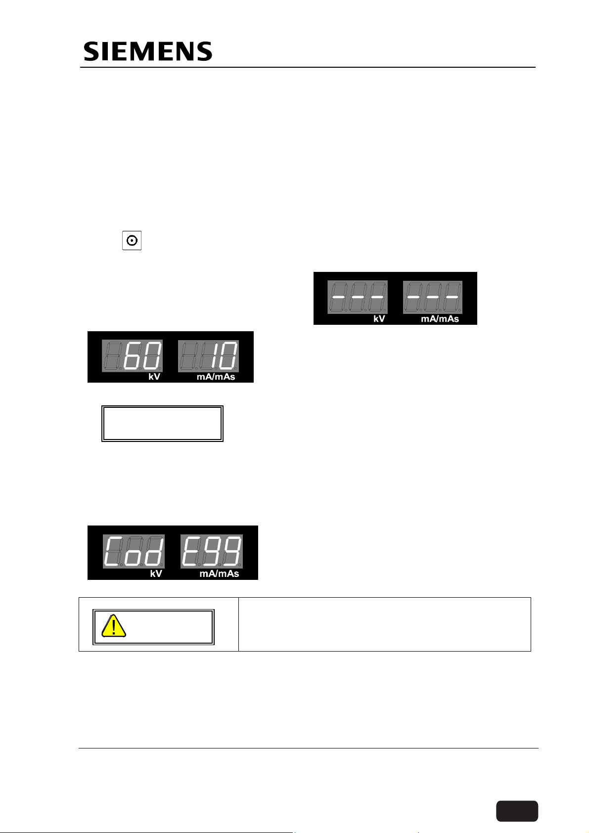
1.3.2.2 Switching ON
Press on the top panel. The kV-mAs display will light up.
The Display will indicate for the set-up
time. (3 seconds approx)
After setup and initial hardware checks
the display changes to the default kV
and mAs settings.
The Control Unit contains Non volatile Memory
NOTICE
which retains the last selected kV and mAs. So the
initial display after set-up will depend on the last
settings done.
The kV & mAs display and settings will now respond to the corresponding switches
on the panel.
In case of any errors while setting up / hardware check / stand-by operation, the
corresponding Error code will be displayed on the same displays.
The display will indicate CodE 99 in case the
unit while setting up/ after set-up detects that
last reset of the unit was due to watch-dog and
not hardware RESET.
If the unit is being installed after six months from
the date of despatch, the capacitors need
WARNING
forming. Refer Service instructions for forming.
1.3.2.3 Up/Down movement
Once the unit is switched on, Check column Up and down movement. Check for the
operation of the limit switches. Do the Up/Dn movements several times to confirm
that there is no wear and tear of belt/bearings and no abnormal noise from the
mechanism.Keep the colum in the upper most position and switch off the unit.
Siemens Ltd. Med India Version 2.0
Page 6 of 9
Copyright © SIEMENS LTD. All rights reserved. For internal use only
The information in this CD is not a controlled document and to be used only for reference.
Before ordering any parts HO-Med-CS-SP to be contacted for obtaining the latest information.
Back
Installation Instructions
After the unit is switched on, the capacitors
charge to 300VDC. (Approx) After switching the
WARNING
unit OFF, it takes about 4 minutes for capacitors
to discharge. The presence of DC voltage is
indicated by Green LED on D61.
1.3.2.4 Cable Connections
Switch off the unit and disconnect the mains supply. Wait for 5 minutes. Open the
front cover and top panel.Check the cable connections as per the table below.
Type Description Specifications
Mains Mains Cable 3 x 1.5 mm sq.(15A Moulded
Plug)- 5mtr length
Control to single Tank HT Cables U & V 6 mm sq. black twisted with braid
Filament cables Y, 12 & 22 3 Core shielded PVC insulated
Collimator Cable 12 Core Grey
Earth Cable 6 mm sq. Black/ Yellow-Green
kV feedback Cable 2 Core shielded PVC insulated
Ground Wire (X) 1.5 mm sq. Yellow
Control to Monitor
Trolley
Control to CCU Mains Cable 3 x 1.5 mm sq.
Interconnections D915.X20 to D506X20 20p FRC
D915.X10 to D506.X10 26p FRC
D915.X11 to D506.X11 16p FRC
D915.X12 to D507.X12 14p FRC
D915.X50 to D507.X50 20p FRC
D915.X8 to D506.X8 10p Bonded
D915.X15 to D981.X7 Bunch
D915.X40 to D509.X40 34p FRC
D507 X70 to D509 X70 20p FRC
D507.X80 to D508.X80 40p FRC
D508.X2 to Collimator.X2 15p D type
D506.X6 to D6.X6 D type soldered connections
D506.X27 to S27 3 Core cable
D508.X90 to CCU X.18 20p FRC
D508.X3 to wire bunch Bunch
D508.X4 to up/dn Motor Control Bunch
D506.X1 to T1 input Bunch
D506.X4 (Pin 1 to 5) to T1 output.
Mains Cable 3 x 1.5 mm sq.
Composite Video Cable 2 x RG 59 with BNC termination
Radiation indication lamp 2 x 1.5 mm. Sq.
Bunch
D506.X4(pin6& 8) to D982 (24V &
0V) (pin 7&8) to D983 (+15 V &0v)
D506.X2 to Single Tank Bunch
Close the top panel and front cover.
1.3.3 Collimator
Switch the unit ON. It will be going to stand by mode.
Siemens Ltd. Med India Version 2.0
Page 7 of 9
Copyright © SIEMENS LTD. All rights reserved. For internal use only
The information in this CD is not a controlled document and to be used only for reference.
Before ordering any parts HO-Med-CS-SP to be contacted for obtaining the latest information.
Back
Installation Instructions
Check the opening and Closing of Iris Collimator. In Fluoroscopy the maximum
opening of the Iris will be limited to the maximum diameter of the Image Intensifier
(6” or 9” as the case may be).
In case of Radiography the Iris Collimator will open automatically to it’s maximum
opening diameter for the cassette exposure.
Use Radiation Protection
Presence of High Tension
Observe Safety Precautions
1.3.4 Exposure
1.3.4.1 Fluoroscopy
Switch ON the unit. Enter in to the Fluoroscopy Mode, press foot switch check for
the Initialization of the Fluoroscopy at the same time radiation Indication, Yellow
LED on the top panel and the lamp on the monitor trolley, will light up.The Image
will appear on the Monitor in ‘Live‘ Mode, by releasing the foot switch The Last
Image On the Monitor will be frozen (LIH function).
1.3.4.2 Exposure
Set the exposure parameters as 60kV, 10mAs.
Pull the recoilable Exposure Release Switch and release an exposure. The yellow
LED on the top panel will light up for duration equal to exposure time.
An audible indication by a muffled sound from single tank as well as from the buzzer
will confirm the working of the inverter and the exposure.
1.3.4.3 Timing
Set 40 kV 160mAs.
Release an exposure. The radiation indication LED will light for 5 sec ± 0.5 sec.
Set 90 kV 80mAs
Release an exposure. The radiation indication LED will light for 5 sec ± 0.5 sec.
Siemens Ltd. Med India Version 2.0
Page 8 of 9
Copyright © SIEMENS LTD. All rights reserved. For internal use only
The information in this CD is not a controlled document and to be used only for reference.
Before ordering any parts HO-Med-CS-SP to be contacted for obtaining the latest information.
Back

Installation Instructions
1.4 General Check
Check for the following before handing over the unit to the customer.
1. Cassette Holder: It should be possible to mount the cassette holder on I.I. ring
in any position of the C arm. A 10” x 12" cassette shall not slip from the
cassette holder in any position of the C arm. It shall be possible to mount the
cassette holder even if the unit is covered with sterile covers on the Image
Intensifier.
2. Sterile Cover: The sterile cover should be easily fitted with the clips provided
and shall not slip out or hinder free movement in any condition.
3. Exposure: Radiation indication as explained tin the section 1.3.4
4. Front cover and top panel are protectively earthed.
5. All the handles shall be of the same colour & smooth in movement.
6. Unit brake pedal shall be fixed with rubber jacket.
7. Footswitch holder shall be fixed on the rear panel of control trolley.
8. Check for all PVC caps are fixed on all visible holes.
Siemens Ltd. Med India Version 2.0
Page 9 of 9
Copyright © SIEMENS LTD. All rights reserved. For internal use only
The information in this CD is not a controlled document and to be used only for reference.
Before ordering any parts HO-Med-CS-SP to be contacted for obtaining the latest information.
Back

Multimobil 5C
Service Instructions
Med
Service Instructions
Version 2.0
Copyright SIEMENS LTD.,Med INDIA
Siemens Ltd. Med India Version 2.0
The information in this CD is not a controlled document and to be used only for reference.
Before ordering any parts HO-Med-CS-SP to be contacted for obtaining the latest information.
Copyright SIEMENS LTD. All rights reserved. For internal use only
Page 1 of 71
Back

Service Instructions
INDEX
1 SAFETY........................................................................................................................................ 5
1.1 SAFETY PRECAUTIONS................................................................................................................ 5
1.2 OVERLOAD PROTECTION............................................................................................................. 5
1.3 RADIATION PROTECTION .............................................................................................................5
1.4 MEASURING WITH OSCILLOSCOPE ................................................................................................ 6
1.5 HANDLING PRECAUTIONS ............................................................................................................ 6
1.6 MECHANICAL SAFETY.................................................................................................................. 6
1.7 MAINTENANCE ............................................................................................................................ 7
1.7.1 Product Disposal.................................................................................................................. 7
1.7.2 Radioprotection Material...................................................................................................... 8
1.7.3 Transformer Oil .................................................................................................................... 8
1.7.4 Plastics................................................................................................................................. 8
1.7.5 Electrolytic Capacitors .........................................................................................................8
2 SERVICING .................................................................................................................................. 9
2.1 TOOLS AND MEASURING INSTRUMENTS REQUIRED ........................................................................ 9
2.2 REPLACING DAMAGED OR MISSING SCREWS ................................................................................. 9
2.3 CLEANING AND DISINFECTING...................................................................................................... 9
2.3.1 Cleaning the Unit ................................................................................................................. 9
2.3.2 Disinfecting......................................................................................................................... 10
2.4 PROTECTING THE SYSTEM FROM FLUIDS..................................................................................... 10
2.5 ROUTINE CHECKS..................................................................................................................... 10
2.5.1 Daily checks ....................................................................................................................... 10
2.5.2 Monthly checks ..................................................................................................................11
2.5.3 Performance Check (Every Six months)............................................................................ 11
2.6 CALIBRATION CHECK ................................................................................................................ 12
2.6.1 Control Voltages ................................................................................................................12
2.6.2 Signals ...............................................................................................................................12
2.6.3 Exposure ............................................................................................................................ 13
2.6.4 Timing ................................................................................................................................13
2.6.5 kVp Measurement.............................................................................................................. 13
2.6.6 mA / mAs Measurement .................................................................................................... 14
2.6.7 Tuning ................................................................................................................................ 14
2.7 YEARLY CHECKS ...................................................................................................................... 14
2.8 PARTS SUBJECT TO WEAR ........................................................................................................ 15
2.9 CHECKS PRIOR TO SWITCH ON AFTER PROLONGED SHELF LIFE .................................................... 15
2.10 CHECKS PRIOR TO TRANSPORT.................................................................................................. 16
3 EXPOSURE CHARTS................................................................................................................ 17
3.1 FOR UNITS WITH 230V INPUT .................................................................................................... 17
3.2 FOR UNITS WITH 110V INPUT .................................................................................................... 18
4 ERROR CODES ......................................................................................................................... 19
5 TROUBLESHOOTING ............................................................................................................... 20
5.1 CHECKING THE LINE VOLTAGE, FUSES AND LEDS ....................................................................... 20
5.1.1 Checking the line voltage................................................................................................... 20
5.1.2 Checking the fuses ............................................................................................................ 21
5.1.3 Checking the LEDs ............................................................................................................ 21
5.2 CHECKING THE CONTROL VOLTAGES ......................................................................................... 22
5.2.1 Checking the Line voltage display. .................................................................................... 22
5.2.2 Checking the Intermediate circuit voltage.......................................................................... 22
5.3 CHECKING FOR EXPOSURE PARAMETERS................................................................................... 22
5.3.1 Checking the Main inverter frequency ............................................................................... 22
Siemens Ltd. Med India Version 2.0
Copyright SIEMENS LTD. All rights reserved. For internal use only
Page 2 of 71
The information in this CD is not a controlled document and to be used only for reference.
Before ordering any parts HO-Med-CS-SP to be contacted for obtaining the latest information.
Back

Service Instructions
5.3.2 Checking the Filament frequency ...................................................................................... 23
5.3.3 Filament current measurement .......................................................................................... 23
5.3.4 Checking of kV and mAs values ........................................................................................ 23
5.4 AUTOMATIC DOSAGE REGULATION ............................................................................................ 24
5.4.1 ADR Stop Mode (Manual).................................................................................................. 25
5.5 REPLACING THE SINGLE TANK.................................................................................................... 25
5.5.1 Replacing the collimator..................................................................................................... 25
5.5.2 Aligning the X-ray field to Image Intensifier ....................................................................... 26
6 CCU AND CAMERA CONTROL ............................................................................................... 27
6.1 INTRODUCTION....................................................................................................................27
6.2 RATINGS................................................................................................................................ 27
6.3 CONNECTION TERMINALS OF CAMERA CONTROL UNIT (CCU) ...................................28
6.4 PERFORMANCES /FUNCTIONS.......................................................................................... 28
6.5 ADJUSTMENTS & EXTERNAL CONTROL .......................................................................... 32
6.6 OSD PARAMETERS SETTINGS ................................................................................................... 35
6.7 PIN ASSIGNMENT ...................................................................................................................... 40
6.7.1 Pin assignment & interfacing details.................................................................................. 41
6.8 PERIODIC CHECKS.................................................................................................................... 41
7 MECHANICAL CHECKS AND ADJUSTMENTS ......................................................................42
7.1 PARTS WHICH NEEDS PERIODIC ADJUSTMENTS ...........................................................................42
7.1.1 BRAKES............................................................................................................................. 42
7.1.2 BEARINGS......................................................................................................................... 43
7.1.3 V-BELT............................................................................................................................... 44
7.1.4 CHAIN ................................................................................................................................ 44
7.2 PARTS WHICH NEEDS SERVICING OR REPLACEMENTS.................................................................. 44
7.2.1 V-Belt .................................................................................................................................44
7.2.2 Bearings ............................................................................................................................. 45
7.2.3 Brake liners ........................................................................................................................ 45
7.3 TROUBLE SHOOTING AND RECTIFICATION ................................................................................... 45
8 APPENDIX I ............................................................................................................................... 48
8.1 SPECIFIC ERROR CODE HANDLING ............................................................................................48
8.1.1 Unit not turning ON ............................................................................................................ 48
8.1.2 No Radiography ................................................................................................................. 49
8.1.3 No Standby ........................................................................................................................51
8.2 INITIALISATION ERROR CODES ................................................................................................... 52
8.2.1 CodE 90 (EPROM CHECKSUM FAILURE) .....................................................................52
8.2.2 CodE 96 (KV SOLL FAILURE) .........................................................................................52
8.2.3 CodE 97 ( mA FAILURE) .................................................................................................. 52
8.2.4 CodE 99 (LAST RESET BY WATCH DOG TIMER)......................................................... 52
8.3 STANDBY ERROR CODES........................................................................................................... 53
8.3.1 CodE 02 : +15 V Supply Error ........................................................................................... 53
8.3.2 CodE 03 & 04 : Iheiz < Istby & Iheiz > Istby ...................................................................... 54
8.3.3 CodE 05 : kVist <> 0 .......................................................................................................... 57
8.3.4 CodE 06 : JR <> 0 ............................................................................................................. 58
8.3.5 CodE 33 : Main Inverter Short Circuit ................................................................................ 59
8.4 EXPOSURE ERROR CODES ............................................................................................... 60
8.4.1 CodE 11 : Main Inverter Short Circuit ................................................................................ 60
8.4.2 CodE 12 : kVist > kVmax ................................................................................................... 61
8.4.3 CodE 13 : Iheiz > Imax OR JR > Jrmax............................................................................ 62
8.4.4 CodE 14 : kVist < kVsoll .................................................................................................... 63
8.4.5 CodE 15 : JR < JRS........................................................................................................... 64
8.4.6 CodE 17 : Exposure terminated by Backup Timer ............................................................ 65
8.4.7 CodE 18 : Premature termination of Exposure .................................................................. 66
8.4.8 CodE 21 : Iheiz > Iheiz maximum ...................................................................................... 67
Siemens Ltd. Med India Version 2.0
Copyright SIEMENS LTD. All rights reserved. For internal use only
Page 3 of 71
The information in this CD is not a controlled document and to be used only for reference.
Before ordering any parts HO-Med-CS-SP to be contacted for obtaining the latest information.
Back

Service Instructions
8.4.9 CodE 22 : Maximum Preparation Time.............................................................................. 68
8.5 PCB LAYOUT DRAWINGS .......................................................................................................... 69
8.5.1 Master card D915 .............................................................................................................. 69
8.5.2 Filament interface PCB D506 ............................................................................................70
8.5.3 ADR and Collimator control PCB D508 ............................................................................. 71
Siemens Ltd. Med India Version 2.0
Copyright SIEMENS LTD. All rights reserved. For internal use only
Page 4 of 71
The information in this CD is not a controlled document and to be used only for reference.
Before ordering any parts HO-Med-CS-SP to be contacted for obtaining the latest information.
Back
Service Instructions
1 Safety
1.1 Safety Precautions
Before opening / closing the covers ensure that the
WARNING
Precaution should be observed while working on the
WARNING
mains is switched off and the plug is removed from
the socket.
Ensure that the protective earth connections of the
sub assemblies are properly connected.
single tank. During continuos fluoroscopy, the
temperature of the oil in the single tank raise. The
thermal switch provided on the single tank cuts off
the radiation after the temperature is reached to
60+5°C. Hence the surface becomes hot and can
cause burns. Avoid contacting the surface of the
single tank at this instance.
1.2 Overload Protection
The unit is designed to work on 110 / 190-240V, single phase, 15A socket. For safety
purposes 16A HRC fuses are provided which will blow when a current exceeding 16A
sustains for its response time.
WARNING
Ensure that the mains socket is properly earthed.
In case of fault if the kV tries to build beyond the safe limit of X-ray tube the protection
circuit blocks the HT.
In case of fault if the Filament current tries to increase beyond the safe limit the
protection circuit blocks filament boosting.
Maximum permissible resistance between the Earthing lead terminal in the control and
on the HT transformer shall not exceed 0.1 ohms.
1.3 Radiation Protection
• Do not put any part of your body in the direct line
of radiation. Collimate the X-ray beam.
WARNING
• Keep maximum possible distance from the object
being radiographed. For this make the best use of
5 mt of recoilable exposure release switch.
• In the room.
• Wear protective clothing (lead Apron).
• Monitor radiation received using the personal TLD-
badges or pen-dosimeter.
Siemens Ltd. Med India Version 2.0
Copyright SIEMENS LTD. All rights reserved. For internal use only
Page 5 of 71
The information in this CD is not a controlled document and to be used only for reference.
Before ordering any parts HO-Med-CS-SP to be contacted for obtaining the latest information.
Back
Service Instructions
1.4 Measuring with oscilloscope
For normal working, the protective earthing of mains must not be removed.
In case system noise is getting coupled to the scope, use the scope in differential
mode.
To measure high voltage use DIFFERENTIAL probe isolated from ground.
1.5 Handling precautions
1. Strictly observe ESD precautions while
handling PCBs and ESD sensitive devices.
WARNING
2. After the unit is switched on, the capacitors
charge to 300VDC. (Approx) After switching
the unit OFF, it takes about 4 minutes for
capacitors to discharge. The presence of DC
voltage is indicated by Green LED on D61.
3. Lead is used for radiation protection inside the
single tank. The collimator flaps are made of
lead. Lead rings are used on the Image
intensifier for counter balancing. Lead is used
inside the C-arm profile for counter balancing.
Hence, special precautions should be
observed during handling these parts to avoid
lead poisoning and contamination.
4. If the Temperature of the single tank exceeds
60°C, then the Temperature. Sensor (switch)
operates and D915 blocks the firing pulses to
the inverter. This overload protection will
automatically again switching ON after the
temperature of single tank goes below the
threshold level (60°C) of the thermal switch
which is indicated by the thermometer symbol
on the top panel. Cool-down periods are
recommended if used extensively.
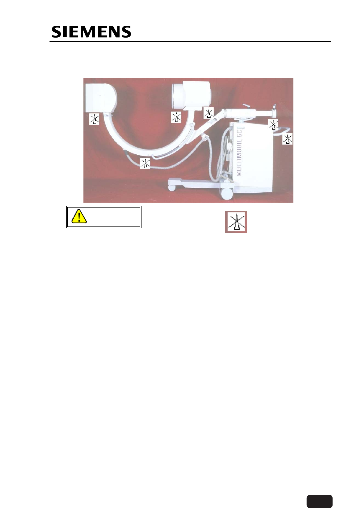
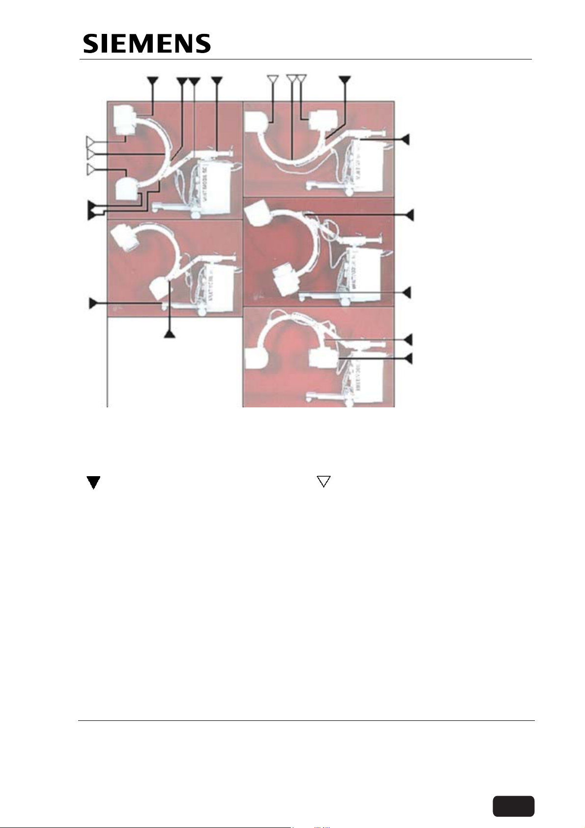
1.6 Mechanical Safety
Due to the manoeuvrability of the system, the collision probability of the image
intensifier and the single tank with the patient or the table is greatly increased if
adequate care is not taken.
While moving various parts of the unit with hand, use of handgrips and handles is
recommended. The figure shows location where there is a danger of crushing for
patient or user due to parts moving relative to each other.
Siemens Ltd. Med India Version 2.0
Copyright SIEMENS LTD. All rights reserved. For internal use only
Page 6 of 71
The information in this CD is not a controlled document and to be used only for reference.
Before ordering any parts HO-Med-CS-SP to be contacted for obtaining the latest information.
Back
Service Instructions
The system should be moved only manually, by the handles provided for this purpose.
whenever exceptions must be made , note the points of potential injury between the
movable system parts and their guide openings. The system areas marked in the
drawings indicate points of crushing or impact hazards for the patient or the operator.
Points of injury for operator
Note: The system shown above is with 9“ II system.The points of injury are identical for 6“ II system.
Points of injury for patients.
1.7 Maintenance
All parts, modules of this product must be tested, inspected, for performance and
safety aspects every 12 months to ensure that the product functions properly and is
safe for patients, operating personnel and other persons.
Every 12 months, trained technical personnel should inspect and if necessary replace
system components of the generator, which may result in hazard due to excessive
wear and tear.
If more frequent inspections and maintenance are required by federal or local
regulations, ensure compliance with them.
1.7.1 Product Disposal
Legal regulations may contain special prescriptions concerning the disposal of this
product. In order to avoid environmental damage and/or personal injury, please inform
SIEMENS Customer Service if you want to put the unit out of operation and dispose it.
Siemens Ltd. Med India Version 2.0
Copyright SIEMENS LTD. All rights reserved. For internal use only
Page 7 of 71
The information in this CD is not a controlled document and to be used only for reference.
Before ordering any parts HO-Med-CS-SP to be contacted for obtaining the latest information.
Back
Loading...