


ISO 9001
Mechanical design
Ordering
|
7118 |
|
LOA2... |
Oil Burner Controls |
LOA3... |
for singleor two-stage pressure-jet burners |
|
with intermittent operation 1) |
|
LOA2... |
LOA3... |
Burner controls for automatic startup, control and supervision of pressure-jet oil burners with an oil throughput of up to 30 kg / h.
The burner controls are tested to EN 230 and CE-certified in compliance with the directives for electromagnetic compatibility.
The LOA2... / LOA3... and this data sheet are intended for use by OEMs that integrate the burner controls in their products!
The burner controls are of plug-in design. The casing is made of impact-proof and heatresistant plastic and accommodates the
–thermal-electric sequence switch which acts on a multiple snap-action switching system
–flame signal amplifier with the flame relay
–lockout reset button with integrated fault indication lamp
Burner control |
refer to table overleaf |
|
Flame detectors |
|
|
– Photo-resistive detectors QRB1... |
refer to data sheet 7714 |
|
– Blue-flame detectors QRC1... |
refer to data sheet 7716 |
|
Plug-in base, without cable gland holder or without cable holder |
|
|
– With screw terminals |
|
AGK11 |
Plug-in base, for clip connection 2) |
|
AGK12 |
– Clipses (single pieces in lots of 100) 2) |
|
AGK 4 408 5625 0 |
– Clipses (10,000 pieces on strap) 2) |
|
AGK 4 408 5626 0 |
– Mounting tool 2) |
|
KF8883 |
– Removal tool 2) |
|
KF8884 |
Cable gland holder for 5 x Pg11, for insertion in plug-in base |
|
AGK65 |
Cable holder, for insertion in plug-in base and introduction of cable |
AGK66 |
|
Spacer (empty casing), to increase the overall height of LOA...- |
AGK21 |
|
types to LAB / LAI height |
|
|
Adapter, for replacing LAB1 / LAI... by LOA... |
|
KF8819 |
(rewiring of plug-in base not required) |
|
|
Service adapter, with signal lamps for making a functional check |
KF8833 |
|
and with jacks for making detector current measurements |
|
|
Remote reset module for use with LOA26... / LOA36... |
|
ARK21A27 |
(printed circuit board) |
|
|
1)For safety reasons (self-test of flame supervision circuit, etc.), at least one controlled shutdown must take place every 24 hours
2)On request only
Landis & Staefa |
CC1N7118E |
December 10, 1997 |
1/13 |

Type summary |
|
The type references given in the table apply to burner controls without base and without |
|
|||||||||||
|
|
|
||||||||||||
|
|
|
flame detector. |
|
|
|
|
|
|
|
|
|
|
|
|
|
|
|
|
|
|
|
|
|
|
|
|
||
Version |
Voltage |
Type reference |
|
Under- |
CE |
t1 |
t3 |
t2 max. |
t3n |
t3n’ |
t4 |
Replace- |
||
|
(VAC) |
|
|
|
voltage |
(s) |
(s) |
(s) |
(s) |
(s) |
(s) |
ment for: |
||
|
|
|
|
|
detection |
|
|
|
|
|
|
|
|
|
|
|
|
|
|
|
|
|
|
|
|
|
|
||
Without bridging contact for the release contact of the oil pre-heater |
|
|
|
|
|
|
|
|
||||||
|
|
|
|
|
|
|
|
|
|
|
|
|||
|
220 |
LOA21.171B273)) |
|
– |
– |
13 |
13 |
10 |
15 |
– |
15 |
LAB1, |
||
Standard |
110 |
LOA21.171B173) |
|
– |
– |
13 |
13 |
10 |
15 |
– |
15 |
LAI1, LAI2 |
||
version |
220 |
LOA21.173A273) |
|
– |
– |
13 |
13 |
10 |
20 |
2 |
20 |
LAI2.2, LAI4 |
||
|
220 |
LOA28.173A271) |
|
x |
– |
13 |
13 |
10 |
2 |
– |
15 |
– |
||
With bridging contact (fr**) for the release contact of the oil pre-heater |
|
|
|
|
|
|
|
|
||||||
|
|
|
|
|
|
|
|
|
|
|
|
|||
|
220 |
LOA22.171B273) |
|
– |
– |
13 |
13 |
10 |
15 |
– |
15 |
LAI2.3 |
||
|
110 |
LOA22.171B173) |
|
– |
– |
13 |
13 |
10 |
15 |
– |
15 |
LAI2.3 |
||
Standard |
220 |
LOA24.171B272) |
|
x |
x |
13 |
13 |
10 |
15 |
– |
15 |
LAI2.3 |
||
version |
110 |
LOA24.171B172) |
|
x |
x |
13 |
13 |
10 |
15 |
– |
15 |
– |
||
|
220 |
LOA24.173A27 |
|
x |
x |
13 |
13 |
10 |
20 |
2 |
20 |
LAI2.3 |
||
|
220 |
LOA24.174A27 |
|
x |
x |
13 |
13 |
10 |
35 |
2 |
35 |
– |
||
With remote |
220 |
LOA26.171B272) |
|
x |
x |
13 |
13 |
10 |
15 |
– |
15 |
– |
||
reset facility |
220 |
LOA36.171A27 |
|
x |
x |
13 |
13 |
10 |
15 |
– |
15 |
– |
||
For flash-steam |
220 |
LOA24.571C27 |
|
x |
x |
6 |
6 |
10 |
20 |
– |
20 |
LAI5 |
||
generators |
|
|
|
|
|
|
|
|
|
|
|
|
|
|
|
|
|
|
|
|
|
|
|
|
|
|
|
||
For incinerator |
220 |
LOA25.173C271) |
|
x |
– |
13 |
13 |
10 |
2 |
– |
15 |
LAB2 |
||
plants or |
110 |
LOA25.173C171) |
|
x |
– |
13 |
13 |
10 |
2 |
– |
15 |
LAB2 |
||
similar |
|
|
|
|
|
|
|
|
|
|
|
|
|
|
|
|
|
|
|
|
|
|
|
|
|
|
|
|
|
|
|
|
|
|
|
|
|
|
|
|
|
|
|
|
1)LOA25... and LOA28... can only be used with photo-resistive detectors QRB1...
Since LOA25... and LOA28... do not feature extraneous light lockout, they do not conform to EN 230
2)It is also possible to use an infrared flicker detector IRD1010 (refer to data sheet 7120)
3)Since LOA21... and LOA22... do not feature undervoltage detection, they do not conform to EN 230
Legend
Times |
tw |
Heating up time of «OH» until contact «OW» |
t1 |
Pre-purge time |
|
|
delivers a signal |
|
|
|
t2 |
Safety time |
t3 |
Pre-ignition time |
|
t3n |
Long post-ignition time |
t3n’ |
Short post-ignition time |
|
t4 |
Interval from establishment of flame to release |
|
|
|
|
of the 2nd fuel valve |
|
|
Functions and components |
|
Burner control output signals |
|
|
|
|
Required input signals |
|
|
|
A’ |
Beginning of startup sequence with burners |
M |
Burner motor |
|
|
using an oil pre-heater «OH» |
|
|
|
A |
Beginning of startup sequence with burners |
K |
Catch of flame relay for locking contact |
|
|
using no oil pre-heater |
|
«tz1» in the case of premature flame |
|
|
|
|
signals or for locking this contact when |
|
|
|
|
flame signal is correct |
|
B |
Time of flame establishment |
OH |
Oil pre-heater |
|
C |
Running position |
OW |
Release contact of «OH» |
|
D |
Controlled shutdown by «R» |
QRB |
Photo-resistive detector |
|
|
|
QRC |
Blue-flame detector |
|
AL |
Alarm device |
|
bl = blue br = brown sw = black |
|
BV |
Fuel valve |
R |
Control thermostat or pressurestat |
|
EK1 |
Lockout reset button |
SA |
Actuator with automatic setback |
|
EK2 |
Remote lockout reset button |
Si |
External pre-fuse |
|
FR |
Flame relay |
TZ |
Thermal-electric sequence switch |
|
fr** |
Bridging contact for release contact of «OH» |
tz... |
Contacts of «TZ» |
|
FS |
Flame signal |
V |
Flame signal amplifier |
|
LED1 |
Indication of flame strength (green) |
W |
Limit thermostat or pressure monitor |
|
L1 |
Indication of faults (red) |
Z |
Ignition transformer |
|
L2 |
Indication of operation (orange) |
|
|
2/13 |
CC1N7118E |
December 10, 1997 |
Landis & Staefa |
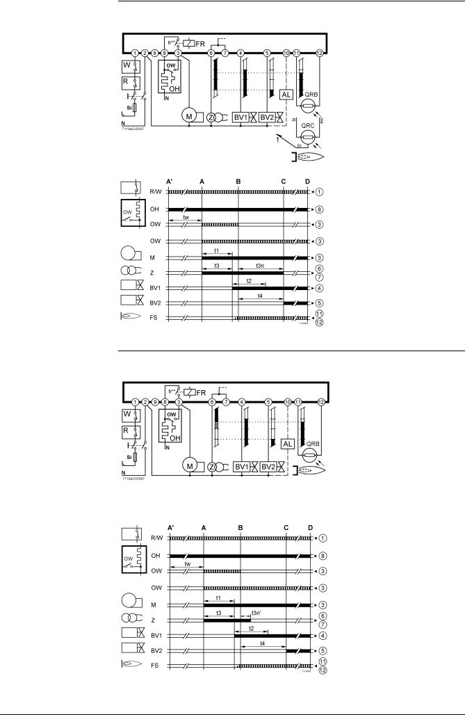
Connection diagram, control sequence
LOA21.171B27
LOA21.171B17
LOA22.171B27
LOA22.171B17
LOA24.171B27
LOA24.171B17
LOA24.571C27
fr** Not provided with the LOA21...
LOA22.171B27 / LOA22.171B17 / LOA24.171B27
LOA24.171B17 / LOA24.571C27
LOA21.171B27 / LOA21.171B17
These types of LOA… may not be used with blue-flame detectors QRC...
LOA25.173C27
LOA25.173C17
LOA28.173A27
fr** Not provided with the LOA28.173A27
LOA25.173C27 / LOA25.173C17
LOA28.173A27
Landis & Staefa |
CC1N7118E |
December 10, 1997 |
3/13 |

Connection diagram, control sequence
LOA21.173A27
LOA24.173A27
LOA24.174A27
fr** Not provided with the LOA21...
LOA24.173A27 / LOA24.174A27
LOA21.173A27
With remote reset module ARK21:
LOA26.171B27
LOA36.171A27
4/13 |
CC1N7118E |
December 10, 1997 |
Landis & Staefa |
 Loading...