


Mux_guide_v06
Siemens Mux_guide_v06, AC43, AC45, MC35i, MC39i User Manual
...
User’s Guide
Multiplexer User's Guide
Siemens Cellular Engines
Version: 06
DocID: Mux_guide_v06

Multiplexer User's Guide
Confidential / Released
s
mo b i l e
Mux_guide_v06 Page 2 of 36 30.06.2004
Document Name:
Multiplexer User's Guide
Version:
06
Date:
June 30, 2004
DocId:
Mux_guide_v06
Status:
Confidential / Released
General notes
Product
is deemed accepted by Recipient and is provided without interface to Recipient’s products.
The documentation and/or Product are provided for testing, evaluation, integration and information
purposes. The documentation and/or Product are provided on an “as is” basis only and may contain
deficiencies or inadequacies. The Documentation and/or Product are provided without warranty of any
kind, express or implied. To the maximum extent permitted by applicable law, Siemens further
disclaims all warranties, including without limitation any implied warranties of merchantability,
completeness, fitness for a particular purpose and non-infringement of third-party rights. The entire risk
arising out of the use or performance of the Product and documentation remains with Recipient. This
Product is not intended for use in life support appliances, devices or systems where a malfunction of
the product can reasonably be expected to result in personal injury. Applications incorporating the
described product must be designed to be in accordance with the technical specifications provided in
these guidelines. Failure to comply with any of the required procedures can result in malfunctions or
serious discrepancies in results. Furthermore, all safety instructions regarding the use of mobile
technical systems, including GSM products, which also apply to cellular phones must be followed.
Siemens or its suppliers shall, regardless of any legal theory upon which the claim is based, not be
liable for any consequential, incidental, direct, indirect, punitive or other damages whatsoever
(including, without limitation, damages for loss of business profits, business interruption, loss of
business information or data, or other pecuniary loss) arising out the use of or inability to use the
Documentation and/or Product, even if Siemens has been advised of the possibility of such damages.
The foregoing limitations of liability shall not apply in case of mandatory liability, e.g. under the German
Product Liability Act, in case of intent, gross negligence, injury of life, body or health, or breach of a
condition which goes to the root of the contract. However, Claims for Damages arising from a breach of
a condition which goes to the root of the contract shall be limited to the foreseeable damage which is
intrinsic to the contract, unless caused by intent or gross negligence or based on liability for injury of
life, body or health. The above provision does not imply a change on the burden of proof to the
detriment of the Recipient. Subject to change without notice at any time. The interpretation of this
general note shall be governed and construed according to German law without reference to any other
substantive law.
Copyright notice
Transmittal, reproduction, dissemination and/or editing of this document as well as utilization of its
contents and communication thereof to others without express authorization are prohibited. Offenders
will be held liable for payment of damages. All rights created by patent grant or registration of a utility
model or design patent are reserved.
Copyright © Siemens AG 2004
Trademark notice
MS Windows
is a registered trademark of Microsoft Corporation.

Multiplexer User's Guide
Confidential / Released
s
mo b i l e
Mux_guide_v06 Page 3 of 36 30.06.2004
Contents
0 Document history..........................................................................................................5
1 Introduction ...................................................................................................................6
1.1 Supported products and related documents..........................................................7
1.2 References ............................................................................................................7
1.3 Term and abbreviations .........................................................................................8
2 Multiplexer protocol – an overview .............................................................................9
2.1 Product concept and architecture ..........................................................................9
2.2 Virtual channels and AT commands ....................................................................10
3 Integrating multiplexer into the customer application ............................................ 11
3.1 Characteristics .....................................................................................................11
3.1.1 Basic requirements ................................................................................11
3.1.2 Restrictions ............................................................................................11
3.1.3 Dependencies between multiplexer channels and restrictions of use ...12
3.1.4 Functions without channel dependencies..............................................12
3.1.5 Timing conditions...................................................................................13
3.1.6 Operation of a second physical serial interface ASC1 (if applicable) ....13
3.2 Multiplexer control and signaling lines .................................................................14
3.2.1 Flow control............................................................................................14
3.2.2 Escape sequence ..................................................................................16
3.3 Power saving .......................................................................................................16
3.4 Bandwidth of logical channels .............................................................................16
4 Structure of the multiplexer protocol........................................................................17
4.1 Introduction of the multiplexer protocol................................................................17
4.2 Data link layer ......................................................................................................17
4.2.1 Flag sequence .......................................................................................18
4.2.2 Address field ..........................................................................................18
4.2.3 Control field............................................................................................ 19
4.2.4 Length indicator .....................................................................................20
4.2.5 Information field .....................................................................................20
4.2.6 Frame checking sequence field (FCS)...................................................20
4.3 State diagrams.....................................................................................................21
4.3.1 Start-up procedure.................................................................................25
4.3.2 DLC establishment.................................................................................25
4.3.3 Information transfer................................................................................ 25
4.3.4 DLC release...........................................................................................26
4.3.5 Close-down procedure........................................................................... 26
4.3.6 Multiplexer control channel ....................................................................26
4.3.7 Multiplexer close down (CLD) ................................................................ 27
4.3.8 Test command (Test).............................................................................27
4.3.9 Modem status command (MSC) ............................................................ 28
4.3.10 Power saving control (PSC)...................................................................30
4.3.11 Non-supported command response (NSC)............................................31
4.4 Example: Establishing logical channels without parameter negotiation ..............32

Multiplexer User's Guide
Confidential / Released
s
mo b i l e
Mux_guide_v06 Page 4 of 36 30.06.2004
5 Multiplexer protocol version control.........................................................................33
5.1 Introduction ..........................................................................................................33
5.2 Multiplexer protocol versions ...............................................................................34
5.3 Implementing version control...............................................................................35
5.3.1 Troubleshooting .....................................................................................35
5.3.2 Coding of “TestCommand” message .....................................................36
5.3.3 Example of “TestCommand” message ..................................................36
Figures
Figure 1: Multiplexer architecture ............................................................................................. 9
Figure 2: Logical flow control and RTS/CTS signaling behind the decoder ........................... 15
Figure 3: Data link layer .........................................................................................................17
Figure 4: Relationship between the customer µC and the GSM engine µC........................... 22
Figure 5: MPI – Startup, DLC establishment and information transfer................................... 23
Figure 6: MP - DLC release and close down.......................................................................... 24
Figure 7: DLC establishment.................................................................................................. 25
Figure 8: Information transfer ................................................................................................. 25
Figure 9: DLC release ............................................................................................................ 26
Figure 10: Multiplexer control channel ...................................................................................26
Figure 11: Modem status command (MSC) ...........................................................................28
Figure 12: Power Saving Control (PSC)................................................................................. 30
Figure 13: Establishing the multiplexer control channel and the logical channel ................... 32
Figure 14: MSC as used in version 3 ..................................................................................... 34
Tables
Table 1: Comparison of multiplexer channels ........................................................................ 10
Table 2: Address field.............................................................................................................18
Table 3: Assignment of the DLCI ...........................................................................................18
Table 4: Use of the command/response bit............................................................................ 18
Table 5: Coding of the control field......................................................................................... 19
Table 6: Version differences for MSC ....................................................................................34
Table 7: IEI coding .................................................................................................................36
Table 8: Coding of “TestCommand” (Example)...................................................................... 36

Multiplexer User's Guide
Confidential / Released
s
mo b i l e
Mux_guide_v06 Page 5 of 36 30.06.2004
0 Document history
This chapter reports modifications and improvements over previous versions of this
document.
Preceding document: “Multiplexer User's Guide” Version 05
New document: “Multiplexer User's Guide” Version 06
Chapter What is new
1.1 Added further supported products.
3.1.1 Added note about closing Multiplexer.
3.1.2 Added note about maximum frame size N1.
4.2.4 Second byte for frame size greater than 127 bytes is not supported.
4.3.5 Corrected description of Close-down procedure.
5 Corrected description of multiplexer version control.
5.3.3 Corrected example.
Preceding document: “Multiplexer User's Guide” Version 04
New document: “Multiplexer User's Guide” Version 05
Chapter What is new
1.1 Added further supported products.
3.1.4 Modified remark on AT&W.
3.1.6 Added chapter “Operation of a second physical serial interface ASC1 (if applicable)”
Preceding document: “Multiplexer User's Guide” Version 03
New document: “Multiplexer User's Guide” Version 04
Chapter What is new
1.1 Added further supported products.
3 - 3.4 Restructured and revised all chapters.
3.1.2, 3.3,
4.3.10
To control SLEEP mode use PSC messages rather than entering AT+CFUN=<n>

Multiplexer User's Guide
Confidential / Released
s
mo b i l e
Mux_guide_v06 Page 6 of 36 30.06.2004
1 Introduction
Siemens GSM engines support the basic option of the multiplexer according to the
ETSI TS 101 369, GSM 07.10 Multiplexer Protocol. This allows a mobile to run a triple
session over a serial link interface. Outside the GSM engine, on the application side of the
serial interface, another multiplexer must be integrated in order to demultiplex the signal and
distribute it on the three virtual channels. The external multiplexer needs to be provided by
the customer.
This document describes how to use the multiplexer and then explains how to design an
external multiplexer and integrate it into an application on top of a Siemens GSM engine.
Multiplexer protocol sources (WinMux2k), provided by Siemens AG, can be obtained on
request from your local distributor. For more detailed information please refer to [5].

Multiplexer User's Guide
Confidential / Released
s
mo b i l e
Mux_guide_v06 Page 7 of 36 30.06.2004
1.1 Supported products and related documents
Supported products
• AC43
• AC45
• MC35i
• MC35i Terminal
• MC39i
• MC45
• MC46
• MC388
• MC5x
• TC35i
• TC35i Terminal
• TC45
• XT55
Related documents
[1] Hardware Interface Description supplied with your GSM engine
[2] AT Command-Set supplied with your GSM engine
[3] Release Notes supplied with your GSM engine
[4] Remote-SAT User's Guide
[5] Multiplexer Driver Developer’s Guide for Windows 2000 and Windows XP
[6] Multiplexer Driver Installation Guide for Windows 2000 and Windows XP
For further documents regarding your GSM engine please refer to the latest Release Notes
supplied with the module.
To visit the Siemens Website you can use the following link:
http://www.siemens.com/wm
1.2 References
[1] Digital Cellular Telecommunications Systems (Phase 2+); Terminal Equipment to
Mobile Station (TE-MS) "Multiplexer Protocol"; ETSI TS 101 369 V7.1.0 (1999-11),
GSM 07.10 Version 7.1.0, Release 199

Multiplexer User's Guide
Confidential / Released
s
mo b i l e
Mux_guide_v06 Page 8 of 36 30.06.2004
1.3 Term and abbreviations
Abbreviation Description
CSD Circuit Switched Data
CTS Clear to Send
DCD Data Carrier Detect
DLCI Data Link Control Identifier
DSB Developer Support Box
DSR Data Set Ready
DTR Data Terminal Ready
FC Flow Control
FFC Flat Flex Cable
GPRS General Packet Radio Service
GSM Global System of Mobile Communication
IEI Information Element Identifier
IP Internet Protocol
MO Mobile originated
MP Multiplexer Protocol
MS Mobile Station
MSDN Microsoft Developer Network
MT Mobile terminated
MUX Multiplexer
OS Operating System
PC Personal Computer
PSC Power saving control
RTS Request to Send
TE Terminal Equipment
UART Universal Asynchronous Receiver Transmitter
Multiplexer User's Guide
Confidential / Released
s
mo b i l e
Mux_guide_v06 Page 9 of 36 30.06.2004
2 Multiplexer protocol – an overview
2.1 Product concept and architecture
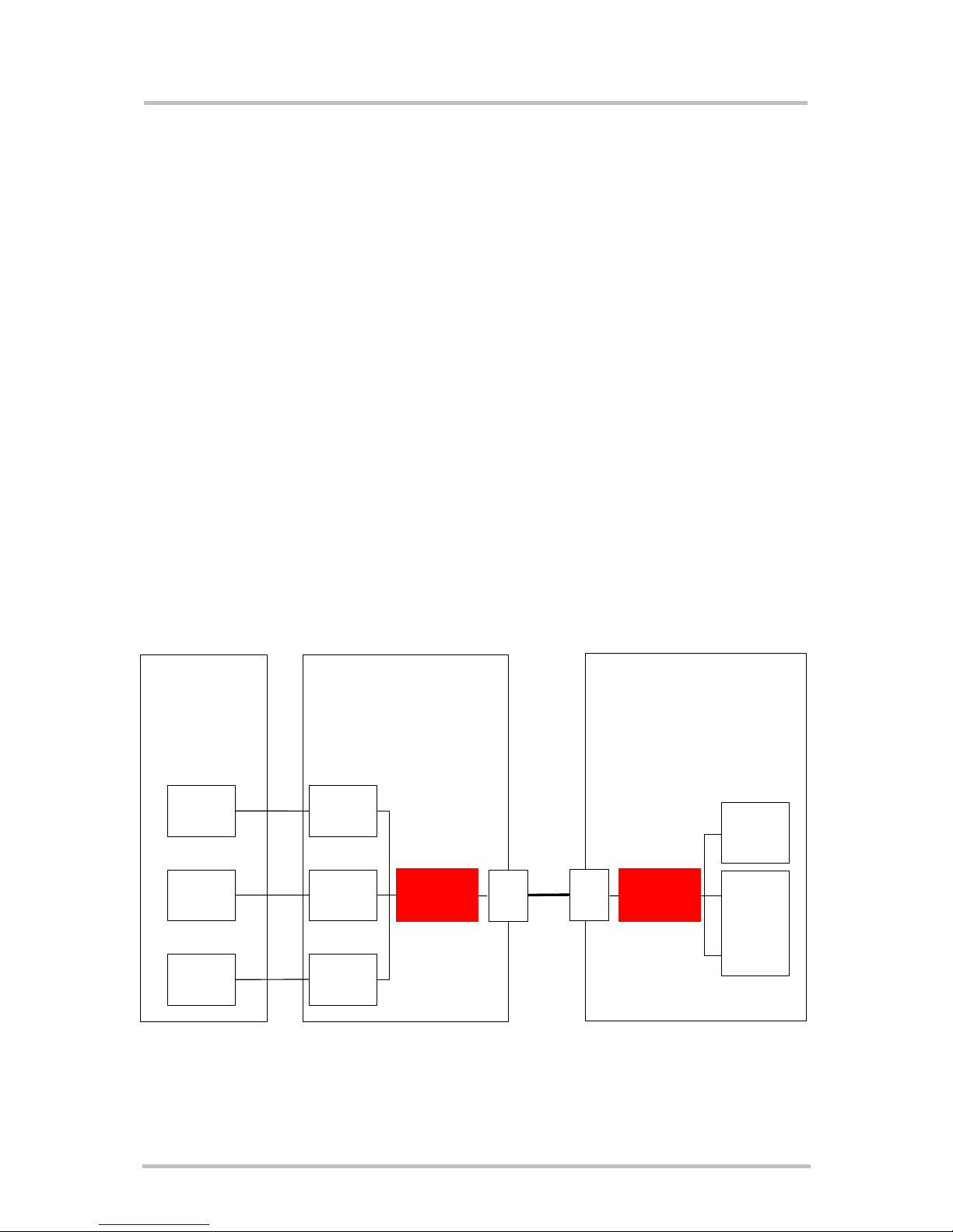
The multiplexer mode enables one serial interface to transmit data to three different customer applications. This is achieved by providing three virtual channels using a
multiplexer (Mux).
This is especially advantageous when a fax/data/GPRS call is ongoing. Using the multiplexer
features, e.g. controlling the module or using the SMS service can be done via the additional
channels without disturbing the data flow; access to the second UART is not necessary.
Furthermore, several accesses to the module can be created with the multiplexer. This is of
great advantage when several independent electronic devices or interfaces are used.
To access the three virtual interfaces, both the GSM engine and the customer application
must contain Mux components which communicate over the multiplexer protocol.
In multiplexer mode, AT commands and data are encapsulated into packets. Each packet
has a channel identification and may vary in length.
Note:
All statements regarding GPRS are valid only for Siemens wireless products capable of
GPRS.
Figure 1: Multiplexer architecture
Terminal programs
or internal programs
integrated in customer application
platform
User application
GSM engine
Channel 1
Channel 2
Channel 3
Terminal 1
Terminal 2
Terminal 3
MP
Data/Fax/
GPRS
supported
Data/Fax
not
supported
Serial
I/O
1
2
3
MUX
conforming
to GSM 07.10
Serial
I/O
MUX
conforming
to GSM 07.10

Multiplexer User's Guide
Confidential / Released
s
mo b i l e
Mux_guide_v06 Page 10 of 36 30.06.2004
2.2 Virtual channels and AT commands
Please note that a cellular engine designed for multiplex operation does not include three
different devices. Only one single air interface (RF part) is available.
As mentioned before the multiplexer enables one serial interface to run three sessions
simultaneously. All incoming or outgoing calls are connected to the device.
Channel 1 supports the full range of functions, which is available without multiplexer tool.
Channel 2 and 3 are connected to a different AT interpreter and support a subset of the
functional range of channel 1, for more details refer to Table 1.
Table 1: Comparison of multiplexer channels
Voice calls
incoming
outgoing
Data / fax calls
incoming
outgoing
SMS
incoming
outgoing
GPRS
connection
Phonebook
management
AT
commands
Channel 1
! ! !
!2)
! !
Channel 2, 3
!
-
!
!2)
!
!1)
! indicates that the functionality is available on the channel
--- indicates that the functionality is not available on the channel
1)
except for AT commands related to data and fax calls
2)
only two channels can be used parallel to transmit GPRS data
Examples
• While a data call is in progress on channel 1, you can send a short message on channel
2 and edit the phonebook on channel 3.
• When receiving a fax on channel 1, you are able to check the battery capacity using the
appropriate AT command on channel 2 or 3.
Note
Due to the technical requirements of multiplexer mode, data and fax calls can only be set up
on logical channel 1 while GPRS connections can be established on every channel. Several
AT commands have a different behavior on channels 2 and 3. Additional information
regarding restrictions and interferences between the channels can be found in chapter 3.1
and in [2].

Multiplexer User's Guide
Confidential / Released
s
mo b i l e
Mux_guide_v06 Page 11 of 36 30.06.2004
3 Integrating multiplexer into the customer application
When designing a multiplexer application, you can create your own sources or take
advantage of the sources delivered upon request by Siemens. The Siemens sources are
packed in a *.zip file which includes a driver for Windows 2000 and Windows XP. See [5] for
a detailed description.
3.1 Characteristics
After establishing the multiplexer mode according to the multiplexer protocol, three logical
channels are available. Please keep the following restrictions and requirements in mind:
3.1.1 Basic requirements
• The GSM engine supports the basic option and UIH Framing according to GSM 07.10.
• Character
framing must be configured for 8 data bits, no parity and 1 stop bit.
If you wish to use multiplexer mode with TC35i modules, be sure not to change this
setting.
• Hardware flow control AT\Q3 is recommended for use with multiplexer mode. If used, it
needs to be set before multiplexer mode is entered.
• Several customer software applications may be able to change the selected settings.
These settings will be stored in the non-volatile memory and used whenever the module
is powered up again. In this case the multiplexer fails to start. To avoid this, it is recommended to re-synchronize all settings before using the multiplexer mode again.
• Before closing the multiplexer make sure that there is no ongoing activity on one of the
channels. For example, check that voice, CSD or GPRS connections have ended and
wait until all pending AT command responses are received.
3.1.2 Restrictions
If the GSM engine is operated in multiplexer mode, the following restrictions apply:
• MO and MT circuit-switched data and fax calls can only be set up on channel 1.
• It is not recommended to use AT+CFUN=<n> for selecting one of the SLEEP modes. For
products supporting Multiplexer Protocol version 3, the best approach to properly control
SLEEP mode in this case is to issue the PSC messages described in Chapter 4.3.10.
The multiplexer cannot be started if one of the following features is activated, nor can these
features be used when multiplexer is active:
• Multiplex mode cannot be started while autobauding (AT+IPR=0) is enabled.
• The multiplexer is not available in charge-only mode and in alarm mode.
• XON/OFF flow control is not supported in multiplexer mode.
The maximum frame size N1 (defined in GSM 07.10) is fixed to 98 bytes and cannot be
changed. The maximum frame size is the same for sending and receiving. See also Chapter
4 in this manual and GSM 07.10.
 Loading...