


MOBY I
Configuration, Installation and
Service
Manual
Table of Contents
General
Introduction to MOBY I
Configuration and Mounting
Guidelines
Mobile Data Memories
Read/Write Devices
Interfaces
Accessories
Documentation
Error Messages
ASCII Table
Compatibility
1
2
3
4
5
6
7
A
B
C
D
6GT2 097-4BA00-0EA2
Published in January, 2002

Safety Guidelines
!
!
!
Qualified Personnel
Correct Usage
!
This manual contains notices which you should observe to ensure your own personal safety, as well as to protect the product and connected equipment. These notices are highlighted in the manual by a warning triangle and are marked as follows according to the level of danger.
Danger
indicates that death, severe personal injury or substantial property damage will result if proper precautions are not taken.
Warning
indicates that death, severe personal injury or substantial property damage can result if proper precautions are not taken.
Caution
indicates that minor personal injury or property damage can result if proper precautions are not taken.
Note
draws your attention to particularly important information on the product, handling the product, or to a particular part of the documentation.
Only qualified personnel should be allowed to install and work on this equipment. For the purposes of the safety notes contained in this manual; qualified persons are defined as persons who are authorized to commission, to ground, and to tag circuits, equipment, and systems in accordance with established safety practices and standards.
Note the following.
Warning
This device and its components may only be used for the applications described in the catalog or the technical description, and only in connection with devices or components from other manufacturers which have been approved or recommended by Siemens.
This product can only function correctly and safely if it is transported, stored, set up, and installed correctly, and operated and maintained as recommended.
Trademarks |
MOBY , SIMATIC and SINEC are registered trademarks of SIEMENS AG. |
|
|
Some of the other designations used in this documentation are also registered trademarks; the |
|
|
owner's rights may be violated if they are used by third parties for their own purposes. |
|
Copyright Siemens AG 1997 All rights reserved |
Disclaimer of Liability |
|
The reproduction, transmission or use of this document or its contents is not permitted without express written authority.
Offenders will be liable for damages. All rights, including rights created by patent grant or registration of a utility model or design, are reserved.
Siemens AG
Automation and Drives
Systems Engineering
Postfach 23 55, D-90713 Fuerth
We have checked the contents of this manual for agreement with the hardware and software described. Since deviations cannot be precluded entirely, we cannot guarantee full agreement. However, the data in this manual are reviewed regularly and any necessary corrections included in subsequent editions. Suggestions for improvement are welcomed.
Siemens AG 1997, 1998, 1999, 2000, 2001, 2002 Technical data subject to change
Siemens Aktiengesellschaft |
Order No. 6GT2 097-4BA00-0EA2 |
Configuration and Mounting Guidelines |
3 |
MOBY I Configuration, Installation and Service Manual |
3-1 |
(4) J31069-D0033-U001-A7.1-7618 |

Configuration and Mounting Guidelines
3.1Basic Requirements
!
Warning
Do not make changes to the devices.
Violation will invalidate interference emission certification (BZT, FCC), CE and the manufacturer's warranty.
FCC Compliance
Statement
Note
Any unauthorized modifications to this device could void the user's authority to operate the equipment.
To choose the correct MOBY I components, apply the following criteria to your particular application.
Transmission distance (i.e., read/write distance)
The amount of data to be transferred
Metal-free spaces for MDS and SLG
Static or dynamic transmission of the data
Speed for dynamic transmission
Tolerances of the tracking
Environmental conditions (e.g., moisture, temperature, chemical influences and so on)
3-2 |
MOBY I Configuration, Installation and Service Manual |
(4) J31069-D0033-U001-A7.1-7618 |
Read/Write Devices
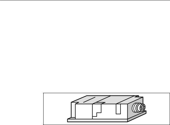
5.4SLG 41/SLG 41-S
Application area The SLG 41 is a low-end read/write device. It is particularly suitable for use when the MDS conveyor system (e.g., pallets) can be physically positioned relatively precisely. The swivel head of the SLG 41 makes it very adaptable to the transportation system.
In dynamic operation, only a small amount of data can be read or written between SLG 41 and MDS.
In contrast to the SLG 41, the antenna of the SLG 41-S is rotated by 90° in the swivel head so that all positions of the transmission window can be implemented.
Ordering data
Technical data
Figure 5-12 |
SLG 41 |
|
Table 5-8 |
Ordering data for SLG 41/SLG 41-S |
|
|
|
|
Read/write device up to 25 mm |
|
|
SLG 41 |
6GT2 001-0AA00 |
|
SLG 41-S (antenna turned 90°) |
6GT2 001-0AA00-ZA23 |
|
SLG plug connector and stub lines |
See chapter 3.10 |
|
|
|
|
Table 5-9 |
Technical data of SLG 41/SLG 41-S |
||
|
|
||
Inductive interface to MDS |
|
||
Data transmission speed |
19200 baud |
||
Read/write distance |
|
||
|
|||
SLG to MDS (max.) |
30 mm (see field data table) |
||
Transmission frequency |
|
||
|
Power |
|
134 kHz |
|
Data |
|
1.81 MHz |
|
|
||
Serial interface to ASM |
6-pin SLG plug connector in acc. w. |
||
|
|
|
DIN 43651 |
|
|
||
Transmission speed |
19200 baud, RS 422 |
||
Line length, ASM to SLG (max.) |
360 m |
||
at 24 V DC |
|
|
|
|
|
||
Supply voltage (via serial interface) |
|
||
Nominal value |
|
24 V DC |
|
Permissible range |
20 to 30 V DC |
||
|
|
|
|
5-12 |
MOBY I Configuration, Installation and Service Manual |
(4) J31069-D0033-U001-A7.1-7618 |
 Loading...