


 Loading...
Operating Instructions Edition 07/2006
Industrial PC
Panel PC 877
simatic
DOCUMENTATION

SIMATIC
Industrial PC
SIMATIC Panel PC 877
Operating instructions
Release 07/2006
A5E00877780-01
Foreword |
1 |
|
|
|
|
Safety information |
2 |
|
|
|
|
Description |
3 |
|
|
|
|
Application planning |
4 |
|
|
|
|
Installation |
5 |
|
|
|
|
Connecting |
6 |
|
Integration into an |
|
|
7 |
||
automation system |
||
|
|
|
Commissioning |
8 |
|
|
|
|
Operation and configuration |
9 |
|
|
|
|
Operation |
10 |
|
|
|
|
Functions |
11 |
|
|
|
|
Maintenance and service |
12 |
|
Alarm, error and system |
|
|
13 |
||
messages |
||
|
|
|
Troubleshooting/FAQs |
14 |
|
|
|
|
Technical data |
15 |
|
|
|
|
Dimension drawings |
16 |
|
|
|
|
Detailed descriptions |
17 |
|
|
|
|
Appendix |
A |
|
|
|
|
ESD directives |
B |
|
List of |
|
|
C |
||
abbreviations / acronyms |
||
|
|

Safety Guidelines
This manual contains notices you have to observe in order to ensure your personal safety, as well as to prevent damage to property. The notices referring to your personal safety are highlighted in the manual by a safety alert symbol, notices referring only to property damage have no safety alert symbol. These notices shown below are graded according to the degree of danger.
Danger
indicates that death or severe personal injury will result if proper precautions are not taken.
Warning
indicates that death or severe personal injury may result if proper precautions are not taken.
Caution
with a safety alert symbol, indicates that minor personal injury can result if proper precautions are not taken.
Caution
without a safety alert symbol, indicates that property damage can result if proper precautions are not taken.
Notice
indicates that an unintended result or situation can occur if the corresponding information is not taken into account.
If more than one degree of danger is present, the warning notice representing the highest degree of danger will be used. A notice warning of injury to persons with a safety alert symbol may also include a warning relating to property damage.
Qualified Personnel
The device/system may only be set up and used in conjunction with this documentation. Commissioning and operation of a device/system may only be performed by qualified personnel. Within the context of the safety notes in this documentation qualified persons are defined as persons who are authorized to commission, ground and label devices, systems and circuits in accordance with established safety practices and standards.
Prescribed Usage
Note the following:
Warning
This device may only be used for the applications described in the catalog or the technical description and only in connection with devices or components from other manufacturers which have been approved or recommended by Siemens. Correct, reliable operation of the product requires proper transport, storage, positioning and assembly as well as careful operation and maintenance.
Trademarks
All names identified by ® are registered trademarks of the Siemens AG. The remaining trademarks in this publication may be trademarks whose use by third parties for their own purposes could violate the rights of the owner.
Disclaimer of Liability
We have reviewed the contents of this publication to ensure consistency with the hardware and software described. Since variance cannot be precluded entirely, we cannot guarantee full consistency. However, the information in this publication is reviewed regularly and any necessary corrections are included in subsequent editions.
Siemens AG |
Order No.: A5E00877780-01 |
Copyright © Siemens AG 2006. |
Automation and Drives |
Edition 07/2006 |
Technical data subject to change |
Postfach 48 48 |
|
|
90437 NÜRNBERG |
|
|
GERMANY |
|
|
Table of contents
1 |
Foreword |
................................................................................................................................................ |
1-1 |
|
1.1 |
Overview.................................................................................................................................... |
1-1 |
2 |
Safety information................................................................................................................................... |
2-3 |
|
|
2.1 |
Safety information...................................................................................................................... |
2-3 |
|
2.2 |
General information ................................................................................................................... |
2-6 |
3 |
Description.............................................................................................................................................. |
3-1 |
|
|
3.1 |
Design........................................................................................................................................ |
3-1 |
|
3.2 |
Technical features...................................................................................................................... |
3-3 |
|
3.3 |
Accessories................................................................................................................................ |
3-5 |
4 |
Application planning................................................................................................................................ |
4-1 |
|
|
4.1 |
Overview.................................................................................................................................... |
4-1 |
|
4.2 |
Unpacking and checking the delivery........................................................................................ |
4-2 |
|
4.3 |
Device identification data........................................................................................................... |
4-3 |
|
4.4 |
Mounting Positions and Fastening............................................................................................. |
4-4 |
|
4.4.1 |
Installation guidelines................................................................................................................. |
4-4 |
|
4.4.2 |
Permitted mounting positions..................................................................................................... |
4-6 |
|
4.4.3 |
Type of fixation........................................................................................................................... |
4-7 |
|
4.4.4 |
Protection against dust and water ............................................................................................. |
4-8 |
|
4.5 |
Mounting cut-out........................................................................................................................ |
4-9 |
|
4.5.1 |
Preparing the mounting cut-out.................................................................................................. |
4-9 |
|
4.5.2 |
Mounting depth of the device................................................................................................... |
4-11 |
|
4.6 |
EMC directive........................................................................................................................... |
4-12 |
5 |
Installation .............................................................................................................................................. |
5-1 |
|
|
5.1 |
Securing the device with clamps................................................................................................ |
5-1 |
|
5.2 |
Securing the device with screws................................................................................................ |
5-3 |
6 |
Connecting ............................................................................................................................................. |
6-1 |
|
|
6.1 |
Connection and operator control components........................................................................... |
6-1 |
|
6.2 |
Connecting the 100 V to 240 V AC power supply...................................................................... |
6-4 |
|
6.3 |
Connecting the 24 V DC power supply...................................................................................... |
6-6 |
|
6.4 |
Connecting the equipotential bonding circuit............................................................................. |
6-7 |
SIMATIC Panel PC 877 |
iii |
Operating instructions, Release 07/2006, A5E00877780-01 |

Table of contents
7 |
Integration into an automation system.................................................................................................... |
7-1 |
|
|
7.1 |
Overview.................................................................................................................................... |
7-1 |
|
7.2 |
Device in a SIMATIC S7 configuration....................................................................................... |
7-2 |
|
7.2.1 |
MPI/PROFIBUS-DP network...................................................................................................... |
7-2 |
|
7.2.2 |
Connecting an S7 automation system....................................................................................... |
7-3 |
|
7.3 |
Networking via Industrial Ethernet............................................................................................. |
7-4 |
8 |
Commissioning....................................................................................................................................... |
8-1 |
|
|
8.1 |
Overview.................................................................................................................................... |
8-1 |
|
8.2 |
Switch on the device.................................................................................................................. |
8-2 |
|
8.3 |
Setting up the Microsoft Windows operating system................................................................. |
8-3 |
|
8.4 |
Installing applications and drivers.............................................................................................. |
8-4 |
|
8.5 |
BIOS settings............................................................................................................................. |
8-9 |
|
8.6 |
Microsoft Windows operating system ...................................................................................... |
8-10 |
|
8.6.1 |
Enables .................................................................................................................................... |
8-10 |
|
8.6.2 |
Windows 2000 Professional..................................................................................................... |
8-11 |
|
8.6.3 |
Windows XP Professional........................................................................................................ |
8-12 |
|
8.7 |
USB.......................................................................................................................................... |
8-13 |
9 |
Operation and configuration.................................................................................................................... |
9-1 |
|
|
9.1 |
Normal operation........................................................................................................................ |
9-1 |
|
9.1.1 |
Switch on the device.................................................................................................................. |
9-1 |
|
9.1.2 |
Logging on to the operating system via the onscreen keyboard (OSK).................................... |
9-3 |
|
9.1.3 |
Switching off the device ............................................................................................................. |
9-4 |
|
9.2 |
Additional Drivers and Applications ........................................................................................... |
9-5 |
|
9.2.1 |
Overview.................................................................................................................................... |
9-5 |
|
9.2.2 |
Calibrating the touch screen, UPDD.......................................................................................... |
9-6 |
|
9.2.3 |
Enable/disable touch functionality.............................................................................................. |
9-8 |
|
9.2.4 |
Windows Security Center (Windows XP Professional only).................................................... |
9-10 |
|
9.2.5 |
KeyTools (for key panel devices only)..................................................................................... |
9-12 |
|
9.2.6 |
Screen keyboard (for touch panel device only)........................................................................ |
9-13 |
|
9.2.7 |
Setbrightness........................................................................................................................... |
9-14 |
|
9.2.8 |
CheckLanguageID ................................................................................................................... |
9-15 |
|
9.2.9 |
Multilingual settings for the operating system.......................................................................... |
9-16 |
|
9.2.10 |
DVD ROM/CD RW................................................................................................................... |
9-18 |
|
9.2.11 |
USB keyboard controller.......................................................................................................... |
9-19 |
10 |
Operation.............................................................................................................................................. |
10-1 |
|
|
10.1 |
Status displays......................................................................................................................... |
10-1 |
|
10.2 |
General control elements......................................................................................................... |
10-2 |
|
10.3 |
Device with key panel .............................................................................................................. |
10-3 |
|
10.3.1 |
Using the keyboard.................................................................................................................. |
10-4 |
|
10.3.2 |
Using the direct control key module....................................................................................... |
10-10 |
|
10.3.3 |
Labelling function keys and softkeys ..................................................................................... |
10-14 |
|
10.3.4 |
Using the integrated mouse................................................................................................... |
10-16 |
|
10.4 |
Device with touch screen....................................................................................................... |
10-17 |
|
10.4.1 |
Using the touch screen .......................................................................................................... |
10-18 |
|
10.5 |
Disk drive................................................................................................................................ |
10-19 |
|
10.6 |
Transferring authorizations .................................................................................................... |
10-20 |
iv |
SIMATIC Panel PC 877 |
Operating instructions, Release 07/2006, A5E00877780-01 |
|
|
|
Table of contents |
11 |
Functions.............................................................................................................................................. |
11-1 |
|
|
11.1 |
Overview.................................................................................................................................. |
11-1 |
|
11.2 |
Safecard on Motherboard (SOM)............................................................................................. |
11-2 |
|
11.3 |
Temperature monitoring........................................................................................................... |
11-4 |
|
11.4 |
Watchdog (WD)........................................................................................................................ |
11-5 |
|
11.5 |
Fan monitoring......................................................................................................................... |
11-6 |
12 |
Maintenance and service...................................................................................................................... |
12-1 |
|
|
12.1 |
Servicing .................................................................................................................................. |
12-1 |
|
12.2 |
Replacement parts................................................................................................................... |
12-3 |
|
12.3 |
Separating the control unit from the computer unit.................................................................. |
12-4 |
|
12.4 |
Installing and removing hardware components....................................................................... |
12-7 |
|
12.4.1 |
Repairs..................................................................................................................................... |
12-7 |
|
12.4.2 |
Open the device....................................................................................................................... |
12-8 |
|
12.4.3 |
Installing and removing memory modules............................................................................. |
12-10 |
|
12.4.4 |
Installing PCI / AT cards ........................................................................................................ |
12-12 |
|
12.4.4.1 |
Notes on the modules............................................................................................................ |
12-12 |
|
12.4.4.2 |
Installing / removing expansion modules............................................................................... |
12-13 |
|
12.4.4.3 |
Exchanging the RAID controller PCI card.............................................................................. |
12-15 |
|
12.4.5 |
Disk drives.............................................................................................................................. |
12-16 |
|
12.4.5.1 |
Options of installing disk drives.............................................................................................. |
12-16 |
|
12.4.5.2 |
Installing / removing a drive bay............................................................................................ |
12-18 |
|
12.4.5.3 |
Removing and installing an optical drive ............................................................................... |
12-21 |
|
12.4.5.4 |
Removing and installing a 3.5" hard disk............................................................................... |
12-24 |
|
12.4.6 |
Replacing the backup battery ................................................................................................ |
12-25 |
|
12.4.7 |
Removing/Installing the Power Supply.................................................................................. |
12-27 |
|
12.5 |
Installing Software.................................................................................................................. |
12-29 |
|
12.5.1 |
General installation procedure............................................................................................... |
12-29 |
|
12.5.2 |
Setting up the partitions for Windows operating systems...................................................... |
12-30 |
|
12.5.3 |
Compatibility of the Restore DVD.......................................................................................... |
12-32 |
|
12.5.4 |
Restoring the factory state of the software using the Restore DVD...................................... |
12-33 |
|
12.5.5 |
Installing Microsoft Windows operating systems................................................................... |
12-35 |
|
12.5.5.1 |
Operating system not installed............................................................................................... |
12-35 |
|
12.5.5.2 |
Booting from the Recovery CD.............................................................................................. |
12-36 |
|
12.5.5.3 |
Installing the Microsoft Windows operating system (not for RAID)........................................ |
12-37 |
|
12.5.5.4 |
Installing the Microsoft Windows operating system (for RAID).............................................. |
12-38 |
|
12.5.6 |
Installing individual drivers..................................................................................................... |
12-39 |
|
12.5.7 |
Operation of two hard disks................................................................................................... |
12-40 |
|
12.5.7.1 |
2 HDD system........................................................................................................................ |
12-40 |
|
12.5.7.2 |
RAID system with Promise Fast Track Controller TX2300.................................................... |
12-41 |
|
12.5.7.3 |
Installing the RAID Controller software.................................................................................. |
12-44 |
|
12.5.8 |
Installing burner and DVD software....................................................................................... |
12-45 |
|
12.5.9 |
Backing up the hard disk........................................................................................................ |
12-46 |
13 |
Alarm, error and system messages...................................................................................................... |
13-1 |
|
|
13.1 |
Boot error messages................................................................................................................ |
13-1 |
|
13.2 |
Introduction to the BIOS beep codes....................................................................................... |
13-3 |
|
13.3 |
BIOS beep codes..................................................................................................................... |
13-5 |
SIMATIC Panel PC 877 |
v |
Operating instructions, Release 07/2006, A5E00877780-01 |

Table of contents
14 |
Troubleshooting/FAQs.......................................................................................................................... |
14-1 |
|
|
14.1 |
General problems..................................................................................................................... |
14-1 |
|
14.2 |
Problems when Using Modules of Third-party Manufacturers................................................. |
14-2 |
|
14.3 |
Temperature limits ................................................................................................................... |
14-3 |
15 |
Technical data ...................................................................................................................................... |
15-1 |
|
|
15.1 |
General technical data............................................................................................................. |
15-1 |
|
15.2 |
Power requirements of the components.................................................................................. |
15-8 |
|
15.3 |
Device with AC voltage supply................................................................................................. |
15-9 |
|
15.4 |
Device with DC voltage supply .............................................................................................. |
15-10 |
|
15.5 |
Keyboard table....................................................................................................................... |
15-11 |
16 |
Dimension drawings ............................................................................................................................. |
16-1 |
|
|
16.1 |
Panel PC 877 dimensional drawing......................................................................................... |
16-1 |
|
16.2 |
Dimensional drawings for the installation of expansion modules ............................................ |
16-3 |
17 |
Detailed descriptions ............................................................................................................................ |
17-1 |
|
|
17.1 |
Motherboard............................................................................................................................. |
17-1 |
|
17.1.1 |
Structure and functions of the motherboard............................................................................. |
17-1 |
|
17.1.2 |
Technical features of the motherboard.................................................................................... |
17-2 |
|
17.1.3 |
Position of the ports on the motherboard................................................................................. |
17-4 |
|
17.1.4 |
External interfaces ................................................................................................................... |
17-5 |
|
17.1.5 |
Front interfaces...................................................................................................................... |
17-13 |
|
17.1.6 |
Internal interfaces................................................................................................................... |
17-18 |
|
17.2 |
Bus board............................................................................................................................... |
17-24 |
|
17.2.1 |
Layout and principle of operation........................................................................................... |
17-24 |
|
17.2.2 |
Assignment of the PCI IRQ channels to the PCI slots........................................................... |
17-25 |
|
17.2.3 |
Exclusive PCI hardware interrupt........................................................................................... |
17-26 |
|
17.2.4 |
ISA slot pin assignment.......................................................................................................... |
17-27 |
|
17.3 |
Operating system licenses..................................................................................................... |
17-29 |
|
17.4 |
Cables.................................................................................................................................... |
17-30 |
|
17.5 |
System resources .................................................................................................................. |
17-31 |
|
17.5.1 |
Currently allocated system resources.................................................................................... |
17-31 |
|
17.5.2 |
System resources used by the BIOS/DOS............................................................................ |
17-32 |
|
17.5.2.1 |
I/O address allocation ............................................................................................................ |
17-32 |
|
17.5.2.2 |
Interrupt Assignments............................................................................................................ |
17-34 |
|
17.5.2.3 |
Memory address assignments............................................................................................... |
17-35 |
|
17.6 |
BIOS setup............................................................................................................................. |
17-36 |
|
17.6.1 |
Overview................................................................................................................................ |
17-36 |
|
17.6.2 |
Starting BIOS Setup............................................................................................................... |
17-37 |
|
17.6.3 |
BIOS setup menus................................................................................................................. |
17-38 |
|
17.6.4 |
Main menu.............................................................................................................................. |
17-40 |
|
17.6.5 |
Advanced menu..................................................................................................................... |
17-51 |
|
17.6.6 |
Security menu........................................................................................................................ |
17-59 |
|
17.6.7 |
Power menu........................................................................................................................... |
17-61 |
|
17.6.8 |
Boot menu.............................................................................................................................. |
17-62 |
|
17.6.9 |
Version menu......................................................................................................................... |
17-64 |
|
17.6.10 |
Exit menu............................................................................................................................... |
17-65 |
|
17.6.11 |
BIOS setup default settings.................................................................................................... |
17-66 |
vi |
SIMATIC Panel PC 877 |
Operating instructions, Release 07/2006, A5E00877780-01 |
|
|
|
Table of contents |
A |
Appendix |
................................................................................................................................................. |
A-1 |
|
A.1 ......................................................................................................... |
Certificates and guidelines |
A-1 |
|
A.1.1 ....................................................................................................... |
Guidelines and declarations |
A-1 |
|
A.1.2 ......................................................................................................... |
Certificates and approvals |
A-3 |
|
A.1.3 ........................................................................................... |
Electrostatic charging of individuals |
A-5 |
|
A.2 ...................................................................................................................... |
Additional support |
A-6 |
B |
ESD directives........................................................................................................................................ |
B-1 |
|
|
B.1 ............................................................................................................................ |
ESD guideline |
B-1 |
C |
List of abbreviations ............................................................................................................./ acronyms |
C-1 |
|
|
C.1 ............................................................................................................................. |
Abbreviations |
C-1 |
|
Glossary ..................................................................................................................................... |
|
Glossary-1 |
|
Index................................................................................................................................................ |
|
Index-1 |
Tables |
|
|
|
Table 4-1 ............................................................................ |
Dimensions for the mounting cut - out in mm |
4-10 |
|
Table 10-1 ..................................................................................................................... |
Keyboard codes |
10-11 |
|
Table 13-1 ........................................................................... |
Converting the beep codes in a Hex display |
13-3 |
|
Table 16-1 ............................................................................................. |
Panel PC 877 dimensions in mm |
16-2 |
|
SIMATIC Panel PC 877 |
vii |
Operating instructions, Release 07/2006, A5E00877780-01 |

Table of contents
viii |
SIMATIC Panel PC 877 |
Operating instructions, Release 07/2006, A5E00877780-01 |
Foreword |
1 |
1.1Overview
Purpose of the manual
These operating instructions contain all the information you need for commissioning and using the SIMATIC Panel PC 877.
It is intended both for programming and testing personnel who commission the device and connect it with other units (automation systems, programming devices), as well as for service and maintenance personnel who install add-ons or carry out fault/error analyses.
Required basic knowledge
A solid background in personal computers and Microsoft operating systems is required to understand this manual. General knowledge in the field of automation control engineering is recommended.
Scope of this manual
This manual applies to devices with the order numbers 6AV781.…
Approvals
For more information, please refer to the chapter "Certificates and Guidelines" in the appendix.
CE marking
For more information, please refer to "Directives and Declarations" in the "Certificates and Guidelines" section of the appendix.
Standards
Please refer to sections "Application planning" and "Technical data".
SIMATIC Panel PC 877 |
1-1 |
Operating instructions, Release 07/2006, A5E00877780-01 |

Foreword
1.1 Overview
Position in the information landscape
The documentation for the Panel PC includes the following sections:
•SIMATIC Panel PC 877, Operating Instructions (compact) with the following information:
–Commissioning
–Legal information
•SIMATIC Panel PC 877, Operating Instructions
The documentation is supplied with the Panel PC in electronic form as a PDF file on the "Documentation and Drivers" CD. The documentation is available in German, English, French, Italian and Spanish.
Additional information about the Windows operating system is available on the Internet at the Microsoft homepage at http://www.Microsoft.com.
Conventions
The following text notation will facilitate reading this manual:
Representation |
Validity |
"File" |
• Terminology that occurs in the user interface, e.g., dialog |
|
names, tabs, buttons, menu commands |
|
• Required parameters such as limit values, tag values |
|
• Path information |
"File > Edit" |
Operational sequences, e.g., menu commands/shortcut menu |
|
commands. |
<F1>, <Shift>+<F1> |
Keys and key combinations |
The term "Panel PC 877", "control unit" and "computer unit" is uniformly referred to as the "device" in these operating instructions. The full term is only used when a concrete reference is necessary.
Note
A note is important information about the product, handling the product or a reference to specific sections of the documentation that require special consideration.
Trademarks
All names labeled with ® symbol are registered trademarks of Siemens AG. Other names used in this documentation may be trademarks, the use of which by third parties for their own purposes could violate the rights of the owner.
HMI®
SIMATIC®
SIMATIC HMI®
SIMATIC WinCC®
SIMATIC WinCC flexible®
Panel PC 877®
1-2 |
SIMATIC Panel PC 877 |
Operating instructions, Release 07/2006, A5E00877780-01 |

Foreword 2.1 Safety information
Safety information |
2 |
2.1Safety information
Warning Emergencies
In the event of a device fault, interrupt the power supply immediately. Inform the customer service personnel responsible. Malfunctions can occur when the operator controls or power cable are damaged or when liquids or foreign objects penetrate the device.
Warning
Following the results of a risk analysis, additional protection equipment on the machine or the system is necessary to avoid endangering persons. With this, especially the programming, configuration and wiring of the inserted I/O modules have to be executed, in accordance with the necessary risk analysis identified safety performance (SIL, PL or Cat.). The intended use of the device has to be ensured.
The proper use of the device has to be verified with a function test on the system. With this programming, configuration and wiring errors can be identified. The test results have to be documented and if necessary inserted into the relevant inputs.
Note
This device corresponds to the regulations of the EU low-voltage directive and the GPSG, verified by conformity with national and international standards (DIN EN, IEC) by a UL approval (cULuc). Please comply with all the information in these operating instructions when assembling the device.
SIMATIC Panel PC 877 |
2-3 |
Operating instructions, Release 07/2006, A5E00877780-01 |
Foreword
2.1 Safety information
Electrical connection
Warning
Disconnect the device from the mains before every intervention.
Do not touch power lines or data transmission lines during electrical storms and do not connect any cables.
System expansions
Only install system expansion devices designed for this device. If you install other expansions, you may damage the system or violate the safety requirements and regulations for radio frequency interference suppression. Contact your technical support team or where you purchased your PC to find out which system expansion devices may safely be installed.
Caution
If you install or exchange system expansions and damage your device, the warranty becomes void.
High frequency radiation
Caution
Unintentional operating situations
High frequency radiation, e.g. from cell phones, can cause unintentional operating situations under some circumstances. Further information is available in the section "EMC requirements" of the "Technical data" chapter.
2-4 |
SIMATIC Panel PC 877 |
Operating instructions, Release 07/2006, A5E00877780-01 |

Foreword 2.1 Safety information
Handling and disposal of lithium batteries
Warning
Danger of explosion and the release of harmful substances!
Do not throw lithium batteries into fire, do not solder onto the cell body, do not open, do not short circuit, do not reverse pole, do not heat above 100 °C, dispose of according to regulations, and protect from direct sunlight, moisture and condensation.
Replace lithium batteries with the same brand or a brand recommended by the manufacturer.
Dispose of used lithium batteries as hazardous waste, individually, in accordance with the local regulations.
Repairs
Only authorized personnel are permitted to repair the device.
Warning
Unauthorized opening of and improper repairs to the device may result in substantial damage to equipment or endanger the user.
SIMATIC Panel PC 877 |
2-5 |
Operating instructions, Release 07/2006, A5E00877780-01 |

Foreword
2.2 General information
2.2General information
Overview
Caution
The device is approved for operation in closed rooms only. The guarantee is void if this stipulation is ignored.
Avoid extreme environmental operating conditions. Protect your device against dust, moisture and heat. For additional information, refer to the Technical data.
Do not place the device in direct sunlight.
Transport
Unpack the device at its installation location. Transport the device only in the original packaging. Do not transport the device when it is mounted.
Notice
Adhere to these stipulations each time the device is transported, otherwise the guarantee is void.
Caution
Condensation
When transporting the device at low temperatures, ensure that no moisture gets on or into the device. This also applies if the device is subjected to extreme changes in temperature.
Commissioning
Allow the device to slowly adjust to room temperature before commissioning the device. Do no place the device near heat radiation. If moisture condensation occurs, wait at least 12 hours before you switch on the device.
Vibration
Optical drives are sensitive to vibration. Inadmissible vibration during operation may result in loss of data or damage to the drive or data medium.
Before transporting the device, wait at least 20 seconds to allow the drive to stop completely.
2-6 |
SIMATIC Panel PC 877 |
Operating instructions, Release 07/2006, A5E00877780-01 |
Foreword 2.2 General information
Tools & downloads
Please check regularly if updates and hotfixes are available for download to your device.
Downloads are available on the Internet at http://www.siemens.com/asis under "Support". Click on "Software Tools & Downloads" on "Overview Panel PCs" Using the global search function, you can then also search for any downloads you require.
Processor and optical drive
Notice
An optical drive should only be operated in a mechanically undisturbed environment without vibrations and shock.
Safety-relevant applications
Warning
Maloperation
Do not perform safety-relevant functions of the user software with the touch screen.
Chemical stability
Caution
Adhere to the information regarding chemical resistance of the panel front. Please go to http://www.siemens.com/asis under "Tools & Downloads" for more information. Enter the article ID 16532108 as the search term. The available articles are displayed.
SIMATIC Panel PC 877 |
2-7 |
Operating instructions, Release 07/2006, A5E00877780-01 |

Foreword
2.2 General information
Sources of light
Notice
Position the screen so that it is not subject to direct sunlight or other strong sources of light.
Defective pixels in the display
At present, the manufacturing process of modern displays does not guarantee that all pixels of the display will be perfect. A small number of defective pixels in the display is therefore unavoidable. This does not present a functional problem as long as the defective pixels are not bunched in one location.
Further information is available in the section "General technical data" of the "Technical data" chapter.
Burn-in dffect on TFT displays
A permanent picture with bright images can lead to a burn-in effect on the TFT LCD. If a screen saver is activated, please observe the following:
•The liquid crystals in screen savers which actuate active black when the backlighting is on, e.g. flying stars "starfield simulation," renew themselves. Pay attention to the length of time the backlighting is activated
•The following applies to screen savers which turn off the the backlighting: Each time the backlighting is turned on, its life is reduced by 50 minutes.
Consider the following carefully:
•Screen saver
•Switch off the backlighting regularly
•Permanent display of the customer application
2-8 |
SIMATIC Panel PC 877 |
Operating instructions, Release 07/2006, A5E00877780-01 |
Description |
3 |
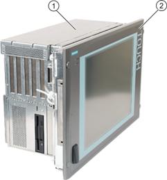
3.1Design
Design
Figure 3-1 Panel PC 877
1 Computer unit
2Control unit
Brief description
The device is available with different control units which are distinguished by the size of the display and by the membrane keyboard or touch screen.
SIMATIC Panel PC 877 |
3-1 |
Operating instructions, Release 07/2006, A5E00877780-01 |

Description
3.1 Design
Keyboard variants
•Color display with backlighting:
–12'' TFT technology with 800 x 600 resolution
–15'' TFT technology with 1024 x 768 resolution
•Membrane keyboard with alphanumeric keys, numeric keys, cursor keys and control keys
•Function keys and softkeys
•Integrated mouse
•LEDs for power supply, temperature, softkeys, <Shift> and <ACK> keys
•Front-mounted USB 2.0 interface for connecting external I/O devices. All fronts are also available without USB interfaces accessible from the front.
Touch screen variants
•Color display with backlighting
–15'' TFT technology with 1024 x 768 resolution
–19'' TFT technology with 1280 x 1024 resolution
•LEDs for power supply and temperature
•Front-mounted USB 2.0 interface for connecting external I/O devices. All fronts are also available without USB interfaces accessible from the front.
For additional information, refer to the Technical data.
3-2 |
SIMATIC Panel PC 877 |
Operating instructions, Release 07/2006, A5E00877780-01 |
Description 3.2 Technical features
3.2Technical features
General features
Slots for add-ons |
• |
2x PCI long |
|
• 2x PCI/ISA shared long |
|
|
• |
1x ISA long |
|
• Note: The RAID1 option takes one PCI slot. |
|
Graphic |
VIA ProSavage 8 |
|
|
Graphics memory 8, 16 or 32 MB taken from main memory |
|
|
CRT: |
|
|
• up to 1600 x 1200 pixels, 60 Hz,16-bit color depth |
|
|
• up to 1280 x 1024 pixels, 100 Hz,32-bit color depth |
|
|
• |
LCD: |
|
• LVDS or DVI up to 1280 x 1024 / 18-bit TFT |
|
Disk drive |
Floppy disk drive |
|
Interfaces |
|
|
PROFIBUS/MPI |
12 Mbps, electrically isolated, compatible to CP 5611 |
|
Ethernet |
10/100 Mbit/s, RJ45 |
|
USB |
2x USB 2.0, high current |
|
Serial |
COM1 V.24, COM2 V.24 |
|
Parallel |
LPT1 |
|
Monitor |
1 x DVI-I |
|
|
VGA monitors can be connected with a DVI/VGA adapter, to be |
|
|
purchased separately. |
|
Keyboard |
PS/2 |
|
Mouse |
PS/2 |
|
SIMATIC Panel PC 877 |
3-3 |
Operating instructions, Release 07/2006, A5E00877780-01 |

Description
3.2 Technical features
Configuration options
Power supply |
• 100V/240V AC, 360 W; wide range; with bridgin |
|
|
|
brief power failures in accordance with NAMUR: |
|
|
maximum 20 ms at 0.85 x Un (Un = rated voltage) |
|
• 24 V DC, 265 VA, optional, only in connection with |
|
|
|
Intel ® Pentium Mobile |
Processor |
• Intel ® Celeron 2 GHz, |
|
|
|
400 MHz Front Side Bus FSB, |
|
|
1024 Kbytes Second Level Cache |
|
• Intel ® Pentium 4 2.8 GHz, |
|
|
|
533 MHz Front Side Bus FSB, |
|
|
512 Kbytes Second Level Cache |
|
• Intel ® Pentium 4 Mobile 2.2 GHz, |
|
|
|
400 MHz Front Side Bus FSB, |
|
|
512 Kbytes Second Level Cache |
Main memory |
2-socket SDRAM DDR266: 256 MB, 512 MB, 1 GB, 2 GB |
|
Hard disks |
• 1 x 3.5" hard disk ≥ 40 GB |
|
|
• 1 x 3.5" hard disk ≥ 80 GB |
|
|
• 2 x 2.5'' hard disks ≥ 60 GB with RAID 1 system SATA |
|
Disk drive |
• |
Without |
|
• |
DVD-ROM |
|
• |
CD-RW/DVD drive |
Operating system |
Without |
|
|
Preinstalled, also provided on the Restore DVD and Microsoft |
|
|
Recovery CD |
|
|
• Windows 2000 Professional MUI* |
|
|
• Windows XP Professional MUI* |
|
|
*MUI: Multi-lingual user interface; German, English, French, Italian, |
|
|
Spanish, Japanese, Korean, Chinese simplified and Chinese |
|
|
traditional |
|
3-4 |
SIMATIC Panel PC 877 |
Operating instructions, Release 07/2006, A5E00877780-01 |

Description
3.3 Accessories
3.3Accessories
The accessories comprise the following components:
Accessories |
Comment |
Order No. |
|
Direct control key module |
|
|
6AV7671-7DA00-0AA0 |
Film for protecting the touch screen panel |
|
|
|
against dirt and scratches |
|
|
|
for 15" touch screen variant |
|
|
6AV7671-4BA00-0AA0 |
for 19" touch screen variant |
|
|
6AV7672-1CE00-0AA0 |
Film for labeling function keys |
|
|
6AV7672-0DA00-0AA0 |
(slide-in labels)1) |
|
|
|
DVI / VGA adapter |
|
|
A5E00254532 |
Backing plate for screw fixing of the 19" touch |
|
|
6AV7672-8KE00-0AA0 |
front |
|
|
|
Multi IO module |
Two parallel and two serial interfaces |
6ES7648-2CA00-0AA0 |
|
SIMATIC PC DiagMonitor |
Software for monitoring local and remote |
6ES7648-6CA02-2YX0 |
|
software V 2.2 |
SIMATIC PCs: |
|
|
|
• |
Watchdog |
|
|
• |
Temperature |
|
|
• |
Fan speed |
|
|
• Hard disk monitoring, SMART |
|
|
|
• |
System monitoring, |
|
|
|
Ethernet monitoring: Heartbeat |
|
|
Communication: |
|
|
|
• Ethernet interface, SNMP protocol |
|
|
|
• OPC for integrating in SIMATIC software |
|
|
|
• |
Client server architecture |
|
|
• Layout of log files |
|
|
SIMATIC PC/PG Image & Partition Creator |
Software for local data backup |
6ES7648-6AA03-0YX0 |
|
Module for DDR RAM memory expansion |
256 MB |
6ES7648-2AG20-0GA0 |
|
|
512 MB |
6ES7648-2AG30-0GA0 |
|
|
1 GB |
6ES7648-2AG40-0GA0 |
|
Remote Kit order version |
|
|
|
Remote Kit, 24V DC, 5m |
|
|
6AV7671-1EA00-5AA1 |
Remote Kit, 24V DC, 10m |
|
|
6AV7671-1EA01-0AA1 |
Remote Kit, 24V DC, 20m |
|
|
6AV7671-1EA02-0AA1 |
Remote Kit, 24V DC, 30m |
|
|
6AV7671-1EA03-0AA1 |
Remote Kit, 120/230 V AC, 5m |
|
|
6AV7671-1EA10-5AA1 |
Remote Kit, 120/230 V AC, 10m |
|
|
6AV7671-1EA11-0AA1 |
Remote Kit, 120/230 V AC, 20m |
|
|
6AV7671-1EA12-0AA1 |
Remote Kit, 120/230 V AC, 30m |
|
|
6AV7671-1EA13-0AA1 |
For further accessories, see Catalog or Siemens MALL
1) You can also find the print templates for the slide-in labels on the Internet at: http://www.siemens.com/asis
At Tools & Downloads>Downloads>Produkt Support>Industrie-PC , enter the entry ID 8782947.
SIMATIC Panel PC 877 |
3-5 |
Operating instructions, Release 07/2006, A5E00877780-01 |

Description
3.3 Accessories
3-6 |
SIMATIC Panel PC 877 |
Operating instructions, Release 07/2006, A5E00877780-01 |

Application planning |
4 |
4.1Overview
Introduction
This section describes the first steps after unpackaging, the permitted mounting positions and the fixation. This section describes the necessary considerations for EMC.
Field of application
The Panel PC is an industry-standard PC platform for demanding tasks in the field of PCbased automation. The Panel PC is designed for on-site use on the machine, installed for example in:
•Switchgear cabinet installation
•Swivel arm installation
•Rack installation
Note
In the following, the term "switchgear cabinet" also refers to rack, mounting rack, switchboard, operator panel and console. The term "device" represents the Panel PC and its variants.
SIMATIC Panel PC 877 |
4-1 |
Operating instructions, Release 07/2006, A5E00877780-01 |

Application planning
4.2 Unpacking and checking the delivery
4.2Unpacking and checking the delivery
Procedure
1.Please check the packaging material for transport damage upon delivery.
2.If any transport damage is present at the time of delivery, lodge a complaint at the shipping company in charge. Have the shipper confirm the transport damage immediately.
3.Unpack the device.
Caution
Do not lie the device on its back. This will avoid any damage to an optical drive which may be present. Lie the front side on a soft surface to avoid damaging the front panel USB port.
4.Keep the packaging material in case you have to transport the unit again.
Notice
The packaging protects the device during transport and storage. Therefore, never dispose of the original packaging material!
5.Please keep the enclosed documentation in a safe place. You will need the documentation when you start up the device for the first time.
6.Check the package contents for completeness and any visible transport damage. Check for completeness using the enclosed scope of delivery list.
7.Should the contents of the package be incomplete or damaged, please inform the responsible supply service immediately and fax us the enclosed form "SIMATIC IPC/PG quality control report".
Warning
Make sure that a damaged device is not installed nor put into operation.
8.Note the identification information as described in the chapter "Identification data of the device".
4-2 |
SIMATIC Panel PC 877 |
Operating instructions, Release 07/2006, A5E00877780-01 |

Application planning 4.3 Device identification data
4.3Device identification data
Procedure
1.Write down the Microsoft Windows Product Key of the Certificate of Authenticity COA in the table at the end of this section. The COA label is only present in preinstalled Windows 2000 Professional or XP Professional and is affixed to the back of the device. You will need the product key during the reinstallation of the operating system.
Figure 4-1 COA label, example
2.Write down the manufacturer's number SVP and the order number, for example "6AV...", and enter it in the table. If repairs are necessary, the device can be identified by the service center on the basis of the SVP number and order number.
Both numbers are located on the rating label on the computer unit at the top of the fan side.
Figure 4-2 Panel PC 877 rating plate, example
3.Enter the Ethernet address of the device: The Ethernet address is located in the "Main" menu of the BIOS setup, "Hardware Options > Ethernet Address."
|
Identification |
Number |
1 |
Microsoft Windows Product Key COA |
|
2SVP number
3 Order number of the device
4Ethernet address
SIMATIC Panel PC 877 |
4-3 |
Operating instructions, Release 07/2006, A5E00877780-01 |

Application planning
4.4 Mounting Positions and Fastening
4.4Mounting Positions and Fastening
4.4.1Installation guidelines
Before installing the device, read the following general notes relating to installation.
Warning
Danger, high voltage
Isolate the power supply to the switchgear cabinet before opening it. Ensure that the power to the switchgear cabinet cannot be turned on accidentally.
Caution
The device is approved for operation in closed rooms only.
•Ensure that the protective contact socket of the building installation is easily accessible and that there is a mains disconnect switch in switchgear cabinet installations.
•Position the screen in an ergonomic position favorable to the user. Choose a suitable installation height.
•Position the screen so that it is not subject to direct sunlight or other strong sources of light.
•Optical drives are susceptible to shock. Shocks during operation can lead to the loss of data or damage to the drive or data carrier. Optical drives are not only suitable for continuous operation.
•Applies to devices which are installed in swivel arm housings: Avoid rapid or jerky movements of the swivel arm during operation. The ensuing forces could lead to possible irreversible damage of the hard disk.
The stops of the swivel arm must be damped in order to avoid any mechanical shock effect to the Panel PC on attachment.
•Applies to devices which are installed in cabinet doors: Prevent the doors being slammed shut. The ensuing forces could lead to possible irreversible damage of the hard disk.
•The device wtih DC power supply applies in the area of the computer unit and above all the power supply connection in accordance with the UL approval as "open type" or "open equipment". For this reason, the device must be installed in a control cabinet or housing that complies with fire-proofing requirements
4-4 |
SIMATIC Panel PC 877 |
Operating instructions, Release 07/2006, A5E00877780-01 |

Application planning 4.4 Mounting Positions and Fastening
Note
The computer unit with AC power supply satisfies fire protection requirements to EN60950-1. It may therefore be installed without additional fire-proofing measures.
•Provide adequate volume in the switchgear cabinet for air circulation and heat transport. Keep at least 10 cm distance between the device and switchgear cabinet.
•Ensure that the maximum air intake temperature, measured 10 cm before the air intake opening on the fan, does not exceed 45°C. The maximum air intake temperature must be accounted for especially when sizing closed switchgear cabinets.
•The minimum distance between the device and the housing is 10 cm on the air output side at the fan.
•Position the device in such a way that the air vents of the housing are not covered up following mounting.
•Ensure there is enough free space in the switchgear cabinet to allow the sheet metal cover to be removed. You will otherwise have to remove the device from the switchgear cabinet or swivel arm when replacing memory or the battery.
•Provide enough free space to add on to the device.
•Equip the switchgear cabinet with struts for stabilizing the mounting cut-out. Install struts where necessary.
•Avoid extreme environmental operating conditions. Protect your device against dust, moisture and heat.
•Install the device in such a way (see ChapterTechnical specifications) that it poses no danger, e.g. by falling over.
•During assembly, please comply with the approved installation positions.
Notice
If you mount the device in an impermissible installation position or you do not observe the environmental conditions (see ChapterTechnical specifications), you endanger the product safety provided by the UL-approval and compliance with the low-voltage directive (via EN 60950-1). In additional, the functionality of the device is no longer guaranteed.
For additional information, refer to the dimension diagrams in the appendix.
SIMATIC Panel PC 877 |
4-5 |
Operating instructions, Release 07/2006, A5E00877780-01 |
Application planning
4.4 Mounting Positions and Fastening
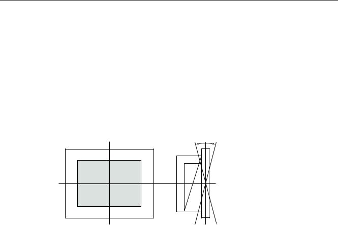
4.4.2Permitted mounting positions
Approval
Certain mounting positions are approved for the equipment that comprises one control unit and one computer unit.
Permitted mounting positions
r r
Vertical installation with deviations between +20° and -20° in the given directions is permissible.
4-6 |
SIMATIC Panel PC 877 |
Operating instructions, Release 07/2006, A5E00877780-01 |
Loading...