


3TF44
s
交流接触器 3TF44,3TF45
Q/SMS 003,GB14048.4,DIN VDE 0660,IEC 60947-4-1
A001253
使用说明书 编号: 4NEB 522 4571-10 e5 中 文
! 注 意
危险电压会引起触电和燃烧。
调整、维修前请先切断电源。
防止触及限定保护的带电部分
保护等级 IP 00 按 IEC 60529
! 触指安全性符合 DIN VDE 0106 第100部分。调整、维修
应由专业人员才能担任,并严格按照使用说明书。
安装
外形尺寸见图Ⅰ(单位:mm):
-图Ⅰa 交流操作
-图Ⅰb 直流操作
注:* 对接地部件的最小距离。
接触器可借助接触器底上滑鞍扣装在35mm宽的标准安装导
轨(DIN EN 50 022)上。或用2只M4螺钉安装,用螺钉安装
时,一定要装平垫圈和弹簧垫圈。在安装时要防止外来颗
粒,例如防止细铁屑进入里面。如果接触器暴露于灰砂、粉
尘及腐蚀性环境中,应加装防护罩。
允许的安装位置见图Ⅱ:
-图Ⅱ a 交流操作
-图Ⅱ b 直流操作
接线
紧固螺钉可用电动螺丝刀旋紧,螺丝刀刀口宽度:5~6mm
即使不用的接线螺钉亦必须拧紧。
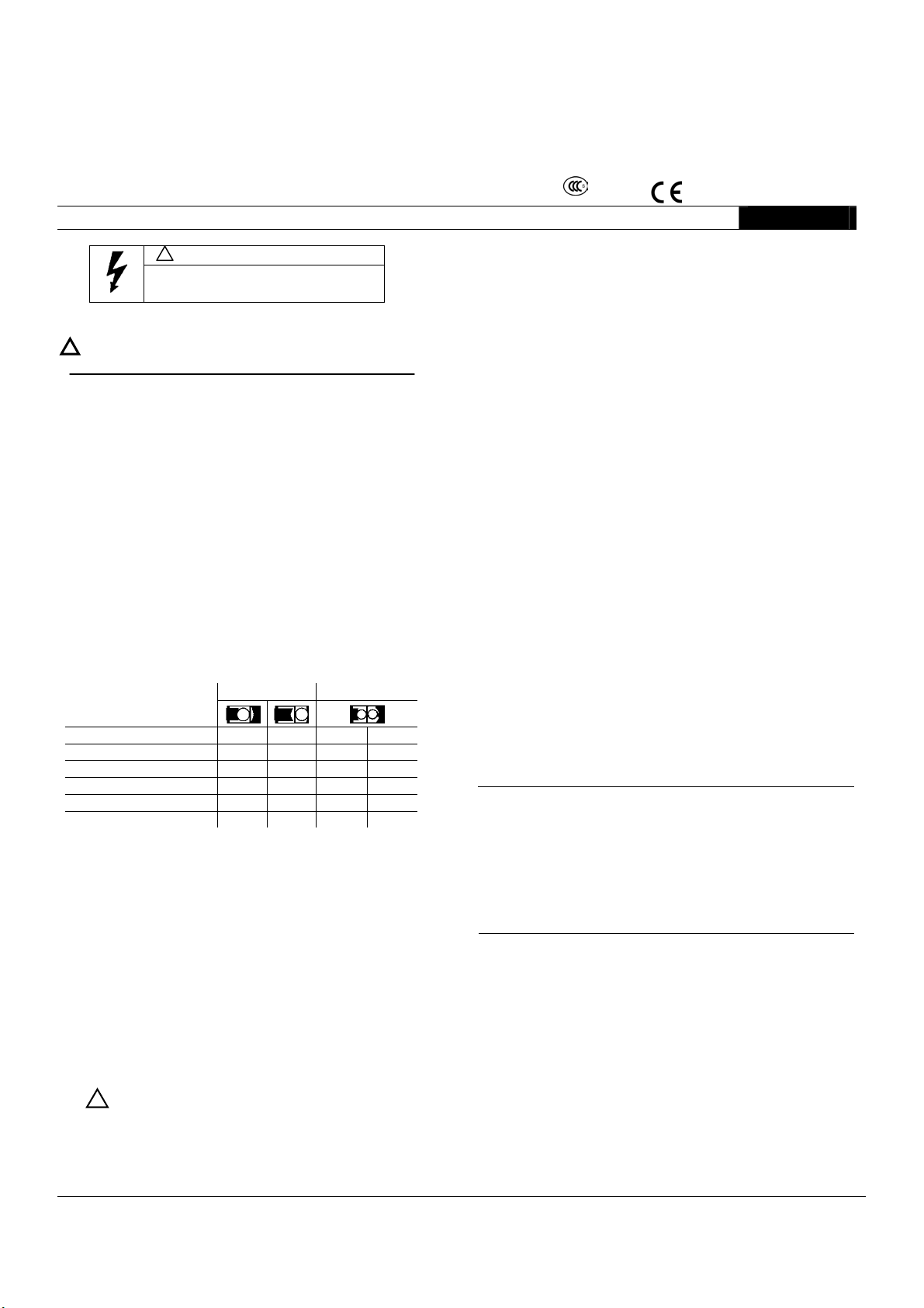
允许的主电路导线截面积
单线连接 双线连接
实心导线 mm2
无套筒端的多股导线 mm2
有套筒端的多股导线 mm2
导线 mm2
AWG制导线
按DIN46231 接线端子mm2
剥线长度 10mm
紧固力矩
允许的辅助电路导线截面积
实心导线 2×0.5~1 mm
2×1~2.5 mm2
具有套筒端的多股导线 2×0.5~1 mm
1~16 1~16
2.5~16 1.5~16
1~16 1~16
2.5~25 1.5~25
14~3 16~3
1~6 1~6
最大16 最大16
最大10 最大16
最大10 最大16
最大10 最大25
最大6 最大3
最大6 最大6
2.5~3.0Nm / 22~26.5 lb.in
2
2
2×0.75~2.5 mm
2
AWG制导线 2×AWG18~12
紧固力矩 0.8~1.4Nm / 7~12lb.in
仅采用75℃铜线
接线端子的电路图及位置见图Ⅲ。
操作
遵守控制电压(见线圈标牌)
接触器通断状态由接触器支架显示:见图Ⅳ。
当系统电压施加且负载连接时,不要靠压下接触器
!
支架来操作接触器。
当发生短路之后,必须检查主触头及灭弧室。
维修保养
** 备注:按照IEC 60947/ VDE 0660 ,配合类型表示:
“配合类型1”:短路电流可引起接触器损坏,如有必要接触器必须更换。“配合类型2”:允许触头有可以容易地分开的熔焊。
下列零部件可以更换:主触头、灭弧室、线圈、辅助触头组。
订货号见产品样本。
只有用本来的备用件才能保证接触器的安全可靠。
清洁
用吸尘器除尘。
辅助触头组
更换情况见图Ⅴ。
灭弧室和主触头
取下灭弧室(图Ⅵ1,2),检查主触头(图Ⅵ3),如有必要可用
螺丝刀轻微分开烧焊触头,氧化的或粗糙的触头可继续使用,不
要修光或擦拭它们。如果触头被电蚀到露出基体材料,则必须更
换触头。
触头更换情况见图Ⅵ4,5,6。
没有必要断开主接触器的连线。检查灭弧室,如有必要则更换
它。只有装好灭弧室才能投入运行(图Ⅵ7,8)。
线圈
线圈的更换见图Ⅶ:
-图Ⅶ a 交流操作
-图Ⅶ b 直流操作
确保线圈电极表面清洁,不要用润滑油或尖物清洁线圈。
技术数据
重量: -交流操作 约 760 g
-直流操作 约 1430 g
允许的环境温度
工作时 -25℃ ~ +55℃
贮存时 -50℃ ~ +80℃
主回路
额定绝缘电压Ui AC 690V
额定工作电流Ie/AC-1(55℃) A 55
额定工作电压
- 230V kW 8.5 11
- 240V kW 9 12
- 400V kW 15 18.5
- 415V kW 17 20
- 500V kW 21 25
- 690V kW 23 23
短路保护:
保护等级按DIN VDE
0660/IEC 60947-4-1 **
-配合类型1 A 80
-配合类型2 A 63
-不熔焊I
-不熔焊I
<100×Ie A 25
K
≥100×Ie A 25
K
辅助回路
额定绝缘电压Ui AC 690V
额定工作电流Ie/AC-15/AC-11 A 5.6 (在电压230V时)
短路保护:
-熔断器
NEOZED 和DIAZED,gL(gG) A 16
-小型断路器(C特性) A 10
其他数据和附件见产品样本
3TF44 3TF45
苏州西门子电器有限公司
XK06-201 0025
电动机额定功率P
熔断器 gL(gG)
/AC-3
N
1
s
Contactor 3TF44, 3TF45
Q/SMS 003,GB14048.4,DIN VDE 0660,IEC 60947-4-1
XK06-201 0025
English
Motor rating P
Fuse-links Duty class gL(gG)
N/AC-3
Instructions
Limited protection against contact with live parts
Degree of protection IP 00 to IEC 60529.
! Safe from finger touch to DIN VDE 0106, Part 100.
Commissioning and maintenance by qualified personnel only.
Follow the operating instructions.
Installation
For dimension drawings see Fig. I (dimensions in mm ).
- Fig. I a a.c. operated
- Fig. I b d.c. operated
* Minimum clearances from earthed parts.
Snap onto 35 mm standard mounting rail to DIN EN 50 022 or fix on a plain surface
with two M4 screws. With screw mounting, always use plain washers and spring
washers.
Cover the contactors during installation if foreign particles, such as swarf, can fall
onto them. Install contactors in a housing if they are exposed to dirt, dust or
aggressive atmospheres.
For permissible mounting positions see
- Fig. II a a.c. operated
- Fig. II b d.c. operated
Connection
The terminal screws can be tightened with a power screwdriver.
Screwdriver blade width: 5 to 6 mm. Tighten all terminal screws even if not used.
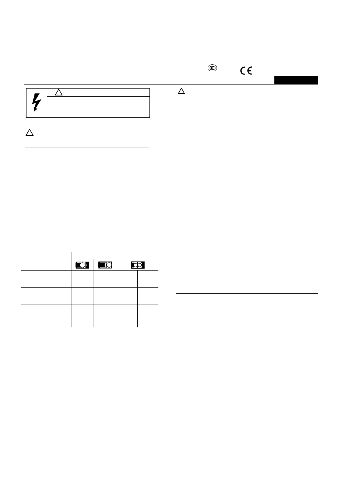
Permissible conductor cross-sections for main conductor:
one terminal connected both terminals connected
Solid (mm2 ) 1 to 16 1 to 16 max.16 max.16
Finely stranded without end
sleeve (mm
Finely stranded with end
sleeve (mm
Stranded (mm2 ) 2.5 to 25 1.5 to 25 max.10 max.25
AWG wires,solid and
stranded
Terminal pin in accordance
with DIN 46231 (mm
Stripped length 10mm
Tightening torque 2.5 to 3.0Nm / 22 to 26.5 lb.in
Permissible conductor cross-sections for auxiliary conductor:
Solid 2×0.5 to 1mm2
2×1 to 2.5 mm
Finely stranded with end sleeve 2×0.5 to 1mm
AWG wires 2×AWG 18 to 12
Stripped length 10mm
Tightening torque standard type 0.8 to 1.4Nm / 7to 12 lb.in
Use 75℃ copper wire only.
For circuit diagrams and position of connection terminals see Fig. III
Operation
Observe operating voltage ( see rating plate of magnet coil ).
The operating state of the contactor is shown at the position indicator; see Fig. IV.
* *Footnote: According to IEC 60947 / VDE 0660,the types of protection mean:
“Assignment type 1 “: Short circuits can cause damage to the contactors making replacement of the equipment necessary.
“Assignment type 2 ”: Easily separable contact welding but no other damage.
! WARNING
can cause electrical shock and burns.
Disconnect power before proceeding
with any work on this equipment.
2
)
2
)
2.5 to 16 1.5 to 16 max.10 max.16
2
)
Hazardous voltage
1 to 16 1 to 16 max.10 max.16
14 to 3 16 to 3 max.6 max.3
1 to 6 1 to 6 max.6 max.6
2
2
2×0.75 to 2.5 mm2
Order No.: 4NEB 522 4571-10 e5
! When the system voltage is applied and the load is connected, do not
Maintenance
The following components can be replaced: Main contacts, arc chute, magnet coil,
auxiliary contact blocks. For Order No. see Catalog.
Only use of original spare parts ensures the operational safety of the contactors.
Cleaning
Remove dust by suction.
Auxiliary contact block
For replacement see Fig. VI.
Arc chute and main contacts
Remove arc chute (Fig. VI/1,2). Check main contacts (Fig. VI/3) .If necessary separate
slightly welded contacts with a screwdriver.
Dark or tough contacts can still function. Do not refinish or grease them. If the contact
facings are eroded so that the carrier material becomes visible the contacts must be
replaced.
For replacement of contacts see Fig. VI/4,5,6. It is not necessary to disconnect the main
conductors. Check the arc chute and replace it if necessary. Put into operation only with
the arc chute fitted (fig. VI/7,8).
Magnet coil
For coil replacement see Fig. VII: - Fig. VII a a.c. coil
Ensure that the pole faces of the magnet coil are clean. Do not use grease solvents or
sharp objects for cleaning.
Technical Data
Weight: a.c. operated approx. 760g
d.c. operated approx. 1430g
Permissible ambient temperature
- Operation -25
- Storage -50
Main circuit
Rated insulation voltage Ui AC 690V
Rated operating current Ie/AC-1(55 ℃) A 55
Rated operational voltage
-230V kW 8.5 11
-240V kW 9 12
-400V kW 15 18.5
-415V kW 17 20
-500V kW 21 25
-690V kW 23 23
Short-circuit protection:
Degree of protection to DIN VDE 0660
part 102A/IEC 60947-4-1 **
-assignment type 1 A 80
-assignment type 2 A 63
-non-welding I
-non-welding IK ≥100×Ie A 25
Auxiliary circuit
Rated insulation voltage Ui AC 690V
Rated operating current Ie/AC-15/AC-11 5.6A at AC 230V
Short-circuit protection:
- Fuse-links
NEOZED and DIAZED, gL (gG) A 16
- Circuit-breaker, C-char A 10
For further data and accessories see Catalog.
2
A001253
operate the contactor by pressing down the contact carrier.
- Fig. VII b d.c. coil
℃ to +55 ℃
℃ to +80 ℃
3TF44 3TF45
K<100×Ie A 25
Siemens Electrical Apparatus Ltd., Suzhou
 Loading...