


www.usa.siemens.com/sdv7
Instruction manual
Type 3AH35-MA vacuum circuit breaker magnetic-actuator operator module
Installation operation maintenance E50001-F710-K378-X-4A00
Answers for infrastructure.
Hazardous voltages and stored energy.
Will cause death, serious injury or property damage.
Even if the circuit breaker and control circuits have been de-energized for a long time, the power supply capacitors will maintain significant stored energy. Always discharge the capacitors before maintenance.
Always de-energize and ground the equipment before maintenance.
Read and understand this instruction manual before using equipment. Maintenance should be performed only by qualified personnel. The use of unauthorized parts in the repair of the equipment or tampering by unqualified personnel will result in dangerous conditions which will cause death, severe injury or equipment damage. Follow all safety instructions contained herein..
Stored energy and high speed moving parts.
Will result in serious injury. Fingers can be crushed by the magnetic actuator.
Do not remove guard panel. Do not operate circuit breaker if guard panel removed.
Important
The information contained herein is general in nature and not intended for specific application purposes. It does not relieve the user of responsibility to use sound practices in application, installation, operation and maintenance of the equipment purchased. Siemens reserves the right to make changes in the specifications shown herein or to make improvements at any time without notice or obligation. Should a conflict arise between the general information contained in this publication and the contents of drawings or supplementary material or both, the latter shall take precedence.
Qualified person
For the purpose of this manual a qualified person is one who is familiar with the installation, construction or operation of the equipment and the hazards involved. In addition, this person has the following qualifications:
Is trained and authorized to
de-energize, clear, ground and tag circuits and equipment in accordance with established safety procedures.
Is trained in the proper care and use of protective equipment, such as: rubber gloves, hard hat, safety glasses or face shields, flash clothing, etc., in accordance with established safety practices.
Is trained in rendering first aid.
Further, a qualified person shall also be familiar with the proper use of special precautionary techniques, personal protective equipment, insulation and shielding materials, and insulated tools and test equipment. Such persons are permitted to work within limited approach of exposed live parts operative at 50 volts or more, and shall, at a minimum, be additionally trained in all of the following:
The skills and techniques necessary to distinguish exposed energized parts from other parts of electric equipment
The skills and techniques necessary to determine the nominal voltage of exposed live parts
The approach distances specified in NFPA 70E and the corresponding voltages to which the qualified person will be exposed
The decision-making process necessary to determine the degree and extent of the hazard and the personal protective equipment and job planning necessary to perform the task safely.

Note:
These instructions do not purport to cover all details or variations in equipment, nor to provide for every possible contingency to be met in connection with installation, operation or maintenance. Should further information be desired or should particular problems arise that are not covered sufficiently for the purchaser’s purposes, the matter should be referred to the local sales office.
The contents of this instruction manual shall not become part of or modify any prior or existing agreement, commitment or relationship. The sales contract contains the entire obligation of Siemens Industry, Inc. The warranty contained in the contract between the parties is the sole warranty of Siemens Industry, Inc. Any statements contained herein do not create new warranties or modify the existing warranty.
Table of contents
Introduction |
04 – 05 |
Installation checks and functional tests |
06 – 09 |
Vacuum interrupter/operator |
10 – 25 |
Maintenance |
26 – 40 |
Overhaul |
41 – 47 |
Technical data and troubleshooting |
48 – 51 |
Introduction
Hazardous voltages and stored energy.
Will cause death, serious injury or property damage.
Even if the circuit breaker and control circuits have been de-energized for a long time, the power supply capacitors will maintain significant stored energy. Always discharge the capacitors before maintenance.
Always de-energize and ground the equipment before maintenance.
Read and understand this instruction manual before using equipment. Maintenance should be performed only by qualified personnel. The use of unauthorized parts in the repair of the equipment or tampering by unqualified personnel will result in dangerous conditions which will cause death, severe injury or equipment damage. Follow all safety instructions contained herein..
Stored energy and high speed moving parts.
Will result in serious injury. Fingers can be crushed by the magnetic actuator.
Do not remove guard panel. Do not operate circuit breaker if guard panel removed.
4
Introduction
The type 3AH35-MA vacuum circuit breaker magnetic actuator module is designed to meet all applicable ANSI, NEMA and IEEE standards. Successful application and operation of this equipment depends as much upon proper installation and maintenance by the user as it does upon the proper design and fabrication by Siemens.
The purpose of this instruction manual is to assist the user in developing safe and efficient procedures for the installation, maintenance and use of the equipment.
Contact the nearest Siemens representative if any additional information is desired.
Signal words
The signal words “danger,” “warning” and “caution” used in this manual indicate the degree of hazard that may be encountered by the user. These words are defined as:
Danger - Indicates an imminently hazardous situation that, if not avoided, will result in death or serious injury.
Warning - Indicates a potentially hazardous situation that, if not avoided, could result in death or serious injury.
Caution - Indicates a potentially hazardous situation that, if not avoided, may result in minor or moderate injury.
Notice - Indicates a potentially hazardous situation that, if not avoided, may result in property damage.
Hazardous procedures
In addition to other procedures described in this instruction manual as dangerous, user personnel must adhere to the following:
1.Always work only on a de-energized circuit breaker. The circuit breaker should be isolated, grounded and have all control power removed before performing any tests, maintenance or repair.
2.Before working on the circuit breaker make sure the capacitors (106.2) are fully discharged (refer to Figure 2: Operator controls and discharging capacitors on page 7). Verify that the CLOSE/OPEN indicator (58.0) is in the OPEN position. Discharge the capacitors (106.2) by unplugging the connector (105.2) on the controller board (105.0). The red LED (106.4) on each of the capacitor boards (106.1) indicate the state of the charge on the capacitors (106.2). When the capacitors (106.2) are discharging, the LEDs are flashing. This indicates hazardous voltage. When the LEDs stop flashing, the capacitors are discharged to a low voltage.
3.Always let an interlock device or safety mechanism perform its function without forcing or defeating the device..
Field service operation and warranty issues
Siemens can provide competent, well-trained field service representatives to provide technical guidance and advisory assistance for the installation, overhaul, repair and maintenance of Siemens equipment, processes and systems. Contact regional service centers, sales offices or the factory for details, or telephone Siemens field service at +1 (800) 347-6659 or +1 (919) 365-2200 outside the U.S.
For medium voltage customer service issues, contact Siemens at +1 (800) 347-6659 or +1 (919) 365-2200 outside the U.S.
5

Installation checks and functional tests
Figure 1: Type 3AH35-MA 27.6 kV 25 kA vacuum circuit breaker magnetic-actuator operator module
Introduction
This section provides a description of the inspections, checks and tests to be performed on the circuit breaker magnetic actuator module only.
The inspections and checks in this section are to be performed with the circuit breaker disconnected and isolated from primary (high-voltage) power sources.
Inspections, checks and tests without control power
De-energizing control power
To de-energize control power in the outdoor circuit breaker, open the control power disconnect device in the relay and control compartment.
The control power disconnect device is normally a fused knife switch. Opening the knife switch de-energizes control power to the circuit breaker operating mechanism. In some outdoor circuit breakers, a molded-case circuit breaker or pullout-type fuse holder may be used in lieu of the fused knife switch. Opening the fused knife switch, or moldedcase circuit breaker, or removing the pullouttype fuse holder accomplishes the desired result: control power is disconnected.
If any maintenance is to be performed, discharge the capacitors.
Fast discharge of capacitors
After control power has been removed, discharge stored energy from the capacitors (refer to Figure 2: Operator controls and discharging capacitors on page 7).
1.Press red Open pushbutton (54.0).
2.Remove the mechanism housing cover sheet (60.1).
3.The green LED on the power supply (104.0 in Figure 2: Operator controls and discharging capacitors on page 7) should not be illuminated. If the green LED is on, open the control power disconnect device in the relay and control compartment.
4.Discharge the capacitors (106.2) by unplugging the connector (105.2) from the controller board (105.0). Do not unplug connector (106.3) from the capacitor boards, or damage to the capacitor board or the controller board may occur. The red LED (106.4) on each of the capacitor boards (106.1) indicates the state of charge of the capacitors (106.2). When the capacitors (106.2) are discharging, the red LEDs are flashing. This indicates a hazardous voltage. When the LEDs stop flashing, the capacitors (106.2) are discharged to a low voltage.
As-found and vacuum-integrity check tests
Perform and record the results of both the asfound insulation test and the vacuumintegrity check (dielectric) test. Procedures for these tests are described in the Maintenance section of this instruction manual beginning on page 26.
6
60.1 |
59.0 |
|
58.0
54.0
105.1
53.0
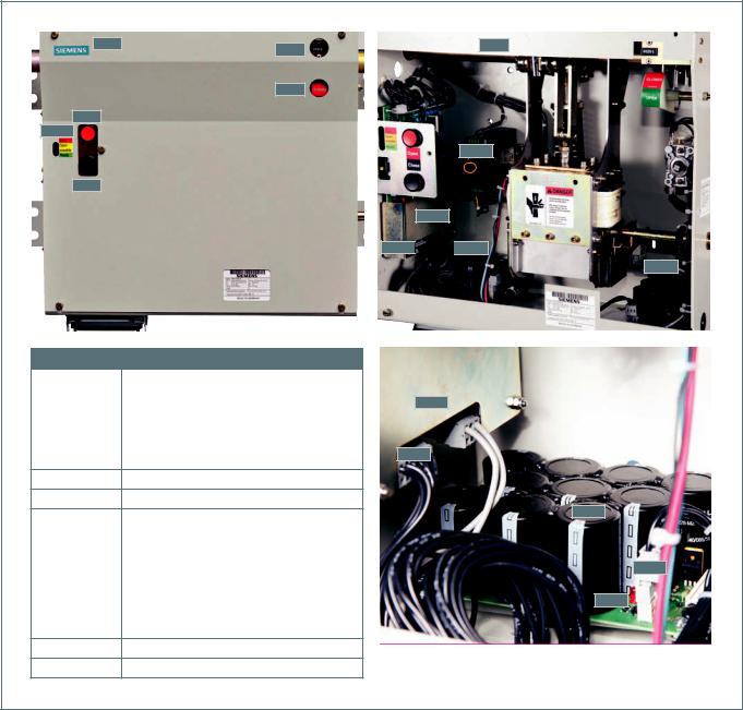
Identification |
Description |
|
|
53.0 |
Close pushbutton (black) |
|
|
54.0 |
Open pushbutton (red) |
|
|
58.0 |
CLOSED/OPEN indicator |
|
|
59.0 |
Operations counter |
|
|
60.0 |
Mechanism housing |
60.1Mechanism housing cover
104.0Power supply (green LED shown circled)
105.0 |
Controller board |
|
|
|
|
105.1 |
Light-emitting diodes (LEDs) |
|
(red, yellow, green) |
||
|
||
|
|
|
105.2 |
Connector for capacitors |
|
|
|
|
106.1 |
Capacitor board |
|
(two or three depending upon rating) |
||
|
||
|
|
|
106.2 |
Capacitor |
106.3Connector (for each capacitor board)
106.4Red LED capacitor discharge state
60.0
104.0
105.0
105.2 
 106.1
106.1
106.1
105.0
105.2
106.2
106.3
106.4
Figure 2: Operator controls and discharging capacitors
7

Hazardous voltages and stored energy.
Will cause death, serious injury or property damage.
Even if the circuit breaker and control circuits have been de-energized for a long time, the power supply capacitors will maintain significant stored energy. Always discharge the capacitors before maintenance.
Always de-energize and ground the equipment before maintenance.
Read and understand this instruction manual before using equipment. Maintenance should be performed only by qualified personnel. The use of unauthorized parts in the repair of the equipment or tampering by unqualified personnel will result in dangerous conditions which will cause death, severe injury or equipment damage. Follow all safety instructions contained herein..
Stored energy and high speed moving parts.
Will result in serious injury. Fingers can be crushed by the magnetic actuator.
Do not remove guard panel. Do not operate circuit breaker if guard panel removed.
8

Automatic capacitor charging
When control power is energized, the controller board (105.0) executes a self-test of the capacitors (106.2) and checks the status of the capacitors (106.2). This self-test runs automatically and regularly. The result of the self-test is stored in the memory of the controller board (105.0).
Capacitor charging check
The capacitor charging system of the circuit breaker must be checked. Control power is required for capacitor charging.
Note: A temporary source of control power and test leads may be required if the control power source has not been connected to the circuit breaker. Refer to the specific wiring information and rating label for your circuit breaker to determine the voltage required and the terminal points where the control voltage signal should be applied. When control power is connected to the circuit breaker, the capacitors should automatically charge.
1.Close the control power disconnect device in the relay and control compartment to energize the circuit breaker control circuit. If not previously charged, the capacitors should charge automatically.
2.Use the Close and Open pushbuttons on the circuit breaker operating mechanism (refer to Figure 3: Operator panel controls on page 10) to first close, and then open the circuit breaker contacts. Verify contact positions visually by observing the OPEN/ CLOSED indicator on the circuit breaker. When the capacitors are fully discharged and control power is applied, the yellow LED lights after approximately 25 seconds. The yellow LED turns off about 5-10 seconds later and the green LED lights.
3.In step 2, when the Close pushbutton was pressed, the circuit breaker should have closed, and the capacitors should have recharged automatically. The meaning of the LEDs (105.1) on the controller board:
a)Green LED indicates ready (energy sufficient for OPEN-CLOSE-OPEN cycle).
b)Yellow LED indicates open possible (energy sufficient for OPEN operation).
c)Red LED indicates error (energy not sufficient for operation).
4.Perform the magnetic actuator-discharge check.
a)Initial status: circuit breaker open.
b)Press red Open pushbutton (54.0).
c)Press black Close pushbutton (53.0).
d)Verify main contact status indicator shows CLOSED.
e)Press red Open pushbutton (54.0) again.
f)Verify main contact status indicator shows OPEN.
5.De-energize the control power by opening the control power disconnect device in the relay and control compartment. Remove the mechanism housing cover sheet (60.1). Do not unplug connector (106.3) from the capacitor boards, or damage to the capacitor board or the controller board may occur. Fast discharge the capacitors (106.2) by unplugging the connector (105.2) on the capacitor controller board (105.0). During fast discharge of the capacitors, a red LED on each capacitor board will flash, indicating that discharge is in process. The process is complete when the red LED stops blinking.
6.After the fast-discharge process, plug in the connector (105.2) to the controller board (105.0).
Final mechanical inspections without control power
1.Make a final mechanical inspection of the circuit breaker. Verify the contacts are in the OPEN position.
2.Check visually that the connectors (106.3) for each capacitor board are firmly connected. Do not disconnect these connections.
3.Reinstall the mechanism housing cover sheet (60.1).
4.Check for loose hardware.
9

Vacuum interrupter/ operator
Identification |
Description |
|
|
|
|
|
|
|
|
|
|
|
|
|
|
53.0 |
Close pushbutton |
|
|
|
|
|
|
(black) |
|
|
|
|
|
||
|
|
|
|
|
59.0 |
||
54.0 |
Open pushbutton |
|
|
|
|
|
|
(red) |
|
|
|
|
|
||
|
|
|
|
|
|
||
58.0 |
CLOSED/OPEN |
|
58.0 |
||||
|
|
|
|
|
|||
indicator |
|
|
|
|
|
||
|
|
|
|
|
|
||
|
|
|
|
54.0 |
|
|
|
59.0 |
Operations counter |
||||||
|
105.0 |
|
|
|
|||
|
LEDs: |
|
|
|
|
|
|
|
Red LED indicates |
|
|
|
|
|
|
|
error (energy not |
|
|
|
|
|
|
|
|
|
53.0 |
|
|
||
|
sufficient for |
|
|
|
|
|
|
|
operation). |
|
|
|
|
|
|
Yellow LED indicates
105.1open possible
(energy sufficient for OPEN position).
Green LED indicates ready (energy sufficient for OPEN- CLOSE-OPEN cycle).
Figure 3: Operator panel controls
10
|
|
|
27.0 |
|
|
|
|
|
|
|
|
|
|
|
|
|
|
|
|
|
|
|
|
|
|
|
|
|
28.0 |
|
|
|
|
|
|
29.0 |
|
|
|||||
|
|
|
|
|
|
|
|
|
|
|
|
|
|
|
|
|
|
||||
|
|
|
|
|
|
|
|
|
|
|
|
|
|
|
|
|
|
|
|
|
|
|
|
20.0 |
|
|
|
|
|
|
|
|
|
|
|
|
|
|
40.0 |
||||
|
|
|
|
|
|
|
|
|
|
|
|
|
|
|
|
|
|
|
|
|
|
Identification |
Description |
|
|
|
|
|
|
|
|
|
|
|
|
|
|
|
|
|
|
|
|
|
|
|
|
|
|
|
30.0 |
|
|
|
|
|
|
|
|
|
|
|
|||
|
|
|
|
|
|
|
|
|
|
|
|
|
|
|
|
|
|
|
|
||
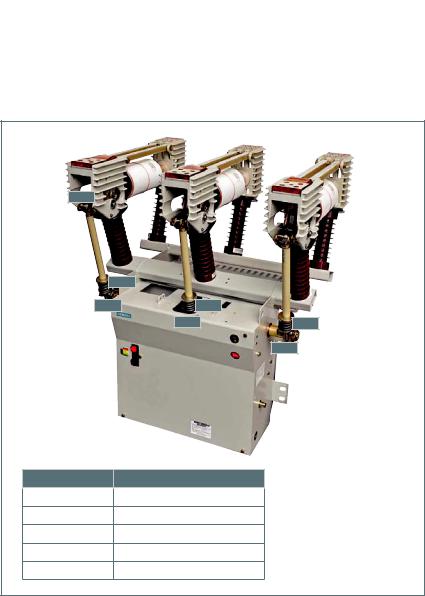
16.0 |
Pole support channels |
|
|
|
|
|
|
|
|
|
|
|
|
|
|
|
|
|
|
|
|
|
|
|
|
|
|
|
|
|
|
|
|
|
|
|
|
|
|
|
|
|
|
16.1 |
Post insulator |
|
|
|
|
|
|
|
|
|
|
|
|
|
|
|
|
|
|
|
|
|
|
|
|
|
|
|
|
|
|
|
|
|
|
|
|
|
|
|
|
|
|
|
|
|
|
|
|
|
|
|
|
|
|
|
|
|
|
|
|
|
|
|
|
20.0 |
Fixed-end pole head |
|
|
|
16.1 |
|
|
|
|
16.1 |
|
|
|
|
|
|
|
||||
|
|
|
|
|
|
|
|
|
|
|
|
|
|
|
|
|
|
|
|
|
|
27.0 |
Fixed-end connection pad |
|
|
|
|
|
|
|
|
|
|
|
|
|
|
|
|
|
|
|
|
|
|
|
|
|
|
|
|
|
|
|
|
|
|
|
|
48.0 |
|
|
|
||
28.0 |
Strut |
|
|
|
|
|
|
|
|
|
|||||||||||
|
|
|
|
|
|
|
|
|
|
|
|
|
|
|
|
|
|
|
|
||
|
|
|
|
|
|
16.0 |
|
|
|
|
16.0 |
|
|
|
|
|
|
|
|
||
29.0 |
Moving-end connection pad |
|
|
|
|||||||||||||||||
|
|
|
|
|
|
|
|
|
|
|
|
|
|
|
|
|
|
|
|
||
|
|
|
|
|
|
|
|
|
|
|
|
|
|
|
|
|
|
49.0 |
|
||
30.0 |
Vacuum interrupter |
|
|
|
|
|
|
|
|
|
|||||||||||
|
|
|
|
|
|
|
|
|
|
|
|
|
|
|
|
|
|
|
|
||
40.0Moving-end pole head
48.0 |
Insulating coupler |
49.0Contact pressure spring
60.0 |
Mechanism housing |
60.0
Introduction
The type 3AH35-MA vacuum circuit breaker magnetic-actuator operator is intended for stationary applications, such as the type SDV7-MA outdoor distribution circuit breaker. The type 3AH35-MA circuit breaker magnetic actuator conforms to the requirements of ANSI/IEEE standards, including C37.04, C37.06, C37.09 and C37.010.
The circuit breaker includes three vacuum interrupters, a magnetic-actuator operating mechanism, necessary electrical controls and an operator housing. In a typical installation, insulating barriers may be located between the vacuum interrupters.
This section describes the operation of each major subassembly as an aid in the operation, maintenance and repair of the circuit breaker.
Vacuum interrupters
The operating principle of the vacuum interrupter is simple. Figure 5: Vacuum interrupter cutaway view is a section view of a typical vacuum interrupter. The entire assembly is sealed after a vacuum is established. The vacuum interrupter stationary contact is connected to the fixedend pole head (20.0) of the circuit breaker.
Figure 4: Vacuum circuit breaker magnetic-actuator operator module
|
|
|
|
|
|
|
|
|
|
|
|
|
|
|
|
|
|
A |
|
|
|
|
|
|
|
|
|
|
Identification |
Description |
|
||
|
|
|
|
|
|
|
|
|
|
|
|
|
|
|
||
|
|
|
|
|
|
|
|
|
|
|
|
|
|
|
|
|
|
|
|
|
|
|
|
|
|
|
|
|
|
|
A |
Fixed contact-current connection |
|
|
|
|
|
|
|
|
|
|
|
|
|
|
|
|
|
|
|
|
|
|
|
|
|
|
|
|
|
|
|
|
|
|
|
|
|
|
|
|
|
|
|
|
B |
|
|
|
B |
Ceramic insulator |
|
|
|
|
|
|
|
|
|
|
|
|
|
|
|
|
|
|
|
|
|
|
|
|
|
|
|
|
|
|
|
|
|
C |
Arc shield |
|
|
|
|
|
|
|
|
|
|
|
|
|
|
|
|
|
|
|
|
|
|
|
|
|
|
|
|
|
|
|
|
D |
Fixed contact |
|
|
|
|
|
|
|
|
|
|
|
|
C |
|
|
|||
|
|
|
|
|
|
|
|
|
|
|
|
|
|
|
||
|
|
|
|
|
|
|
|
|
|
|
E |
Moving contact |
|
|||
|
|
|
|
|
|
|
|
|
|
|
|
|
||||
|
|
|
|
|
|
|
D |
|
|
|
|
|||||
|
|
|
|
|
|
|
|
|
|
|
|
F |
Metal bellows |
|
||
|
|
|
|
|
|
|
E |
|
|
|
|
|||||
|
|
|
|
|
|
|
|
|
|
|
|
|
|
|
|
|
|
|
|
|
|
|
|
|
|
|
|
|
|
|
G |
Guide |
|
|
|
|
|
|
|
|
|
|
|
|
|
|
|
|
|
|
|
|
|
|
|
|
|
|
|
|
|
|
|
|
H |
Moving contact-current connection |
|
|
|
|
|
|
|
|
|
|
|
|
|
|
|
|
|
|
|
|
|
|
|
|
|
|
|
B |
|
|
|
|
|
|
|
|
|
|
|
|
|
|
|
|
|
|
|
|
|
|
|
|
|
|
|
|
|
|
|
F |
|
|
|
|
|
|
|||
|
|
|
|
|
|
|
|
|
|
|
|
|||||
|
|
|
G |
|
|
|
|
|
|
|||||||
|
|
|
|
|
|
|
|
|
|
|
||||||
|
|
|
H |
|
|
|
|
|
|
|||||||
|
|
|
|
|
|
|
|
|
|
|
|
|
|
|
|
|
|
|
|
|
|
|
|
|
|
|
|
|
|
|
|
Figure 5: Vacuum interrupter cutaway view |
|
11
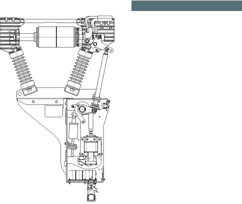
48.6
49.0 |
|
63.3 |
49.0 |
63.5 |
49.0 |
63.1
Identification Description
48.6Angled lever
49.0Contact pressure spring
63.1Lever - phase C
63.3Lever - phase A
63.5Lever - phase B
Figure 6: Vacuum circuit breaker magnetic-actuator operator module
The vacuum interrupter movable contact is connected to the flexible shunt (29.1) associated with the other pole head and to the driving mechanism of the circuit breaker. The metal bellows provide a secure seal around the movable contact, preventing loss of vacuum while permitting motion of the movable contact along the axis of the vacuum interrupter.
When the two contacts separate, an arc is initiated that continues conduction up to the following current zero. At current zero, the arc extinguishes and any conductive metal vapor that has been created by and supported the arc condenses on the contacts and on the surrounding arc shield. Contact materials and configuration are optimized to achieve arc motion and to minimize switching disturbances.
Primary connections
Figure 4: Vacuum circuit breaker magneticactuator operator module on page 11 illustrates the pad provision to accept the primary connections. Each circuit breaker has three connection pads at the fixed end of the vacuum interrupter, and three connection pads on the flexible connectors that are associated with the movable contact of the vacuum interrupter. Interconnecting bus in the circuit breaker enclosure connects these connection pads to the roof bushing terminals. Bolting hardware is M12 x 1.75 grade 8. Torque M12 bolts to 52 ft-lb (70 Nm).
Phase barriers (if applicable)
For certain ratings, barriers of glass-polyester insulating material are attached to the circuit breaker and provide suitable electrical insulation between the vacuum interrupter and primary conductors and the enclosure.
Magnetic actuator operating mechanism
The energy needed for closing and tripping is stored in two or three capacitor banks (106.0) (depending on circuit breaker rating) charged to approximately 160 V. The self-discharging function is activated by removing the connector (105.2) of the controller board (105.0). Do not unplug connector (106.3) from the capacitor boards, or damage to the capacitor board or the controller board may occur. The capacitors are charged automatically when control power is applied. From fully discharged condition, the capacitors are fully charged in approximately 30-35 seconds.
The capacitor charge is monitored constantly by the controller board (105.0). If the control power source fails, the capacitors can initiate one open operation initiated by the operatormounted pushbutton (54.0). This last operation must be initiated within 300 s after loss of control power supply. Within 300 s after loss of operator control power, the circuit breaker can perform one open operation initiated by a remote command if the remote command is from a wet (powered) contact.
The green LED, which indicates that energy is sufficient for an OPEN-CLOSE-OPEN operation is illuminated as long as the voltage of the capacitors is greater or equal to 150 V.
12
Vacuum interrupter/operator module
The vacuum interrupter/operator module consists of the three poles, each with its vacuum interrupter and primary insulators, mounted above the common magnetic actuator operating mechanism housing (60.0). This module is shown in Figure 6: Vacuum circuit breaker magnetic-actuator operator module on page 12.
Construction
Each of the circuit breaker poles is fixed to the pole support channel (16.0) by two cast-resin insulators. The insulators also connect to the fixedand moving-end pole heads (40.0) that in turn support the ends of the vacuum interrupter. The pole supports are aluminum castings or sheet steel (for 15.5 kV and
27.6 kV up to 25 kA). Refer to Figure 3: Operator panel controls on page 10 and Figure 4: Vacuum circuit breaker magneticactuator operator module on page 11, Figure 7: Pole assembly on page 14 and Figure 8: Magnetic-actuator operating mechanism on page 15.
The magnetic actuator mechanism and all the control and actuating devices are installed in the operator housing.
The CLOSE-OPEN indicator, Open pushbutton, Close pushbutton, the LEDs on the controller board and the operation counter are located on the front of the mechanism housing.
The control connector for the control and signalling cables is a multi-contact plug. The mating control plug wiring connects to the terminal blocks in the relay and control compartment.
Circuit breaker pole (refer to Figure 7: Pole assembly on page 14)
The vacuum interrupter is bolted to the fixedend pole head (20.0), which is rigidly connected to the pole support channel (16.0) by the post insulator (16.1). The moving contact end of the vacuum interrupter is stabilized against lateral forces by a centering ring (28.1) on the moving-end pole head (40.0). The external forces due to switching operations and the contact pressure are absorbed by the struts (28.0).
Current-path assembly (refer to Figure 7: Pole assembly on page 14)
The current-path assembly consists of the fixed-end pole head (20.0), the stationary contact and the moving contact, plus a flexible shunt (29.1) between the moving contact terminal clamp (29.2) and the moving-end connection pad (29.0).
Vacuum interrupter (refer to Figure 7: Pole assembly on page 14)
The moving-contact motion is aligned and stabilized by a guide bushing. The metal bellows follows the travel of the contact and seals the vacuum interrupter against the surrounding atmosphere.
Switching operation
The sequence of actions involved in various switching operations are described in this section. Refer to Figure 7: Pole assembly on page 14 and Figure 8: Magnetic-actuator operating mechanism on page 15.
When a closing command is initiated, the controller board (105.0) checks the circuit of the magnetic actuator’s coil (101.3) for integrity. After the integrity check has been proven satisfactory, the capacitors (106.2) power the magnetic actuator (101.0). This process is monitored by the controller board (105.0). The electrical current in the coil (101.3) generates a magnetic field. An attractive force causes the anchor (101.4) moving upwards.
The coupling rod (62.8) moves upwards by compressing the opening springs (64.0) by means of the jack shaft (63.0). The contact pressure springs (49.0) are compressed and the insulating couplers (48.0) are moved upwards. Through the angled levers (48.6) the contacts in the vacuum interrupter (30.0) are closed.
The forces that occur when the action of the insulating coupler (48.0) is converted into the action of the moving contact along the axis of the vacuum interrupter are absorbed by the guide link (48.9) that pivots on the movingend pole head and the eye bolt.
13
In the closed state, the necessary contact pressure is maintained by the contact pressure springs (49.0) and the atmospheric pressure. The magnetic actuator maintains a stable closed position without supplemental energy input. The contact pressure spring automatically compensates for arc erosion, which is very small.
When a opening command is initiated, the controller board (105.0) checks the circuit of the magnetic actuator’s coil (101.3) for integrity. After the integrity check has been proven satisfactory, the capacitors (106.2) power the magnetic actuator coil (101.3) with a reverse current. This opposes the attactive force between the magnetic actuator (101.0) and the permanent magnet. Due to the energy stored in the contact pressure springs (49.0) and the opening spring (64.0), the magnetic actuator’s anchor (101.4) is pushed downwards. This opening process is supported by the opening spring (64.0). In the OPEN position the opening spring assures that the ambient pressure does not close the contacts in the vacuum interrupters (30.0).
Operating mechanism
The operating mechanism is comprised of the mechanical and electrical components required to:
1.Charge the capacitors for providing sufficient electrical energy to move the magnetic actuator and close or open the circuit breaker.
2.Mechanisms to release closing and opening actions.
3.Means of transmitting force and motion to each of the three vacuum interrupters.
4.Operate all these functions automatically through the capacitors (106.2), the controller board (105.0). auxiliary switch 3SV9 (68.0), the lock out switch (114.0) and the opening spring (64.0).
5.Provide indication of the circuit breaker status (OPEN/CLOSED), indicate capacitor energy status (green LED indicates ready, yellow LED indicates OPEN possible and red LED indicates error) and number of operations.
Figure 7: Pole assembly |
|
|
|
|
|
|
|
|
|
|
|
|
|
|
|
|
|
|
|
|
|
|
|
|
|
|
|
|
|
|
Identification |
Description |
|
|
|
|
|
|
|
|
|
|
|
|
|
|
|
|
|
|
|
|
|
|
|
|
|
|
|
|
|
|
|||
|
|
27.0 |
|
|
|
|
|
|
|
|
|
|
|
|
29.1 |
|
29.0 |
|
|
|
16.0 |
Pole support channels |
||||||||||
|
|
|
|
|
|
|
|
|
|
|
28.0 |
|
|
|
|
|
|
|
|
|
|
|
|
|
|
|
|
|
|
|
|
|
|
|
|
|
|
|
|
|
|
|
|
|
|
|
|
|
|
|
|
|
|
|
|
|
|
|
|
|
|
|
|
||
|
|
|
|
|
|
|
|
|
|
|
|
|
|
|
|
|
|
|
|
|
29.1 |
|
|
|
|
|
16.1 |
Post insulator |
||||
|
|
20.0 |
|
|
|
|
|
|
|
|
|
|
|
|
29.2 |
|
|
|
|
|
|
|
40.0 |
|
|
|
||||||
|
|
|
|
31.0 |
|
|
|
|
|
|
|
|
|
|
|
|
|
|
|
|
|
|
|
|
|
20.0 |
Fixed-end pole head |
|||||
|
|
|
|
|
|
|
|
|
|
|
30.0 |
|
|
36.0 |
|
|
|
|
|
|
|
|
|
|
|
|
|
|
|
|||
|
|
|
|
|
|
|
|
|
|
|
|
|
|
|
|
|
|
|
|
|
|
27.0 |
Fixed-end connection pad |
|||||||||
|
|
|
|
|
|
|
|
|
|
|
|
|
|
|
|
|
|
|
|
|
|
|
|
|
|
|
|
|
|
|
||
|
|
|
|
|
|
|
|
|
|
|
|
|
|
|
|
|
|
|
48.6 |
|
|
|
|
|
|
|
||||||
|
|
|
|
|
|
|
|
|
|
|
|
|
|
|
|
|
|
|
|
|
|
|
|
|
|
|
|
|||||
|
|
|
|
|
|
|
|
|
|
|
|
|
|
|
28.1 |
|
|
|
|
|
|
|
|
48.9 |
|
|
28.0 |
Strut |
||||
|
|
|
|
|
|
|
|
|
|
|
|
|
|
|
|
|
48.9 |
|
|
|
|
|||||||||||
|
|
|
|
|
|
|
|
|
|
|
|
|
|
|
|
|
|
|
|
|
|
|
|
|
|
|
|
|
|
|
|
|
|
|
|
|
|
|
|
|
|
|
|
|
|
|
|
|
|
|
|
|
|
|
|
|
|
|
|
|
|
|
|
28.1 |
Centering ring |
|
|
|
|
|
|
|
|
|
|
|
|
|
|
|
|
|
|
|
|
|
|
|
|
|
|
|
|
|
|
|
|
|
|
|
|
|
|
|
|
|
|
|
|
|
|
|
|
|
|
|
|
|
|
|
|
|
|
|
|
|
|
|
|
|
|
|
|
|
|
|
|
16.1 |
|
|
|
|
|
|
|
16.1 |
|
|
|
|
|
|
|
|
|
|
|
|
29.0 |
Moving-end connection pad |
||||
|
|
|
|
|
|
|
|
|
|
|
|
|
|
|
|
|
|
|
|
|
|
|
|
|
|
|
|
|
|
|
|
|
|
|
|
|
|
|
|
|
|
|
|
|
|
|
|
|
|
|
|
|
|
|
|
|
|
|
|
|
|
|
|
29.1 |
Flexible shunt |
|
|
|
|
|
|
|
|
|
|
|
|
|
|
|
|
|
|
|
|
|
48.0 |
|
|
|
|
|
||||||
|
|
|
|
|
|
|
|
|
|
|
|
|
|
|
|
|
|
|
|
|
|
|
|
|
|
|
|
|
|
|
|
|
|
|
|
|
|
|
|
|
|
|
|
|
|
|
|
|
|
|
|
|
|
|
|
|
|
|
|
|
|
|
|
29.2 |
Terminal clamp |
|
|
|
|
|
|
|
|
|
16.0 |
|
|
16.0 |
|
|
|
|
|
|
|
|
|
|
|
|
|
|
|
|
|
|||
|
|
|
|
|
|
|
|
|
|
|
|
|
|
|
|
|
|
|
|
|
|
|
|
|
|
|
|
|
|
|||
|
|
|
|
|
|
|
|
|
|
|
|
|
|
|
|
|
|
|
|
|
|
|
|
|
|
|
|
|
|
|
30.0 |
Vacuum interrupter |
|
|
|
|
|
|
|
|
|
|
|
|
|
|
|
|
|
|
|
49.0 |
|
|
|
|
|
|
|
|
|
||||
|
|
|
|
|
|
|
|
|
|
|
|
|
|
|
|
|
|
|
|
|
|
|
|
31.0 |
Fixed contact |
|||||||
|
|
|
|
|
|
|
|
|
|
|
|
|
|
|
|
|
|
|
|
|
|
|
|
|
|
|
|
|
|
|
||
|
|
|
|
|
|
|
|
|
|
|
|
|
|
|
|
63.0 |
|
64.3 |
|
|
|
|
|
|
|
|||||||
|
|
|
|
|
|
|
|
|
|
|
|
|
|
|
|
|
|
|
|
|
|
|
|
|
|
|||||||
|
|
|
|
|
|
|
|
|
|
|
|
|
|
|
|
|
|
|
|
36.0 |
Moving contact |
|||||||||||
|
|
|
|
|
|
|
|
|
|
|
|
|
|
|
|
|
|
|
|
|
|
|
|
|
|
|
|
|
|
|
||
|
|
|
|
|
|
|
|
|
|
|
|
|
|
|
|
|
|
|
|
62.9 |
|
|
|
|
|
|
|
|
|
|||
|
|
|
|
|
|
|
|
|
|
|
|
|
|
|
|
|
|
|
|
|
|
|
|
40.0 |
Moving-end pole head |
|||||||
|
|
|
|
|
|
|
|
|
|
|
|
|
|
|
|
|
|
|
|
|
|
|
|
|
|
|
|
|
|
|
||
|
|
|
|
|
|
|
|
|
|
|
|
|
|
|
|
|
|
|
|
|
|
|
|
|
|
|
|
|
|
|
|
|
|
|
|
|
|
|
|
|
|
|
|
|
|
|
|
|
|
|
|
|
62.8 |
|
|
|
|
|
|
|
48.0 |
Insulating coupler |
|||
|
|
|
|
|
|
|
|
|
|
|
|
|
|
|
|
|
|
|
|
|
|
|
|
|
|
|
|
|
|
|
||
|
|
|
|
|
|
|
|
|
|
|
|
|
|
|
|
|
|
|
|
|
|
|
|
|
|
|
|
|
|
|
|
|
|
|
|
|
|
|
|
|
|
|
|
|
|
|
|
|
|
|
|
|
|
|
|
|
|
|
|
|
|
|
|
48.6 |
Angled lever |
|
|
|
|
|
|
|
|
|
|
|
|
|
|
|
|
|
|
|
|
|
|
|
|
|
|
|
|
|
|
|
|
|
|
|
|
|
|
|
|
|
|
|
|
|
|
|
|
|
|
|
|
|
|
|
|
|
|
|
|
|
|
|
|
48.9 |
Guide link |
|
|
|
|
|
|
|
|
|
|
|
|
|
|
|
|
|
|
|
|
|
|
|
|
|
|
|
|
|
|
|
|
|
|
|
|
|
|
|
|
|
|
|
|
|
|
|
|
|
|
|
|
|
|
|
|
|
|
|
|
|
|
|
|
49.0 |
Contact pressure spring |
|
|
|
|
|
|
|
|
|
|
|
|
|
|
|
|
|
|
|
|
|
|
|
|
|
|
|
|
|
|
|
|
|
|
|
|
|
|
|
|
|
|
|
|
|
|
|
|
|
|
|
|
|
|
|
|
|
|
|
|
|
|
|
|
60.0 |
Mechanism housing |
|
|
|
|
|
|
|
|
|
|
|
|
|
60.0 |
|
|
|
|
|
|
|
|
|
|
|
|
|
|
|
|
|||
|
|
|
|
|
|
|
|
|
|
|
|
|
|
|
|
|
|
|
|
|
|
|
|
|
|
|
|
|
|
|
||
|
|
|
|
|
|
|
|
|
|
|
|
|
|
|
|
|
|
|
|
|
|
|
|
|
|
|
|
|
|
|
62.8 |
Coupling rod |
|
|
|
|
|
|
|
|
|
|
|
|
|
|
|
|
|
|
|
|
|
|
|
|
|
|
|
|
|
|
|
|
|
|
|
|
|
|
|
|
|
|
|
|
|
|
|
|
|
|
|
|
|
|
|
|
|
|
|
|
|
|
|
|
62.9 |
Coupling link |
|
|
|
|
|
|
|
|
|
|
|
|
|
|
|
|
|
|
|
|
|
|
|
|
|
|
|
|
|
|
|
|
|
|
|
|
|
|
|
|
|
|
|
|
|
|
|
|
|
|
|
|
|
|
|
|
|
|
|
|
|
|
|
|
63.0 |
Jack shaft |
|
|
|
|
|
|
|
|
|
|
|
|
|
|
|
|
|
|
|
|
|
|
|
|
|
|
|
|
|
|
|
|
|
|
|
|
|
|
|
|
|
|
|
|
|
|
|
|
|
|
|
|
|
|
|
|
|
|
|
|
|
|
|
|
64.3 |
Lever |
|
|
|
|
|
|
|
|
|
|
|
|
|
|
|
|
|
|
|
|
|
|
|
|
|
|
|
|
|
|
|
|
|
14

Figure 8: Magnetic-actuator operating mechanism
Circuit breaker shown in OPEN position.
|
|
63.0 |
63.5 |
|
|
|
|
|
|
|
101.1 |
109.0 |
54.0 |
|
|
|
|
104.0 |
64.0 |
|
|
|
|
105.1 |
|
54.1 |
|
105.0 |
53.0 |
|
101.3 |
|
|
||
|
|
60.0 |
|
105.2 |
|
113.0 |
|
|
|
||
|
|
106.0 |
|
105.2 |
|
|
|
|
|
106.1 |
|
|
|
|
106.3 |
|
|
|
106.4 |
113.0
113.0
106.1
|
59.0 |
64.3 |
|
|
58.0 |
|
68.1 |
62.9 |
101.1 |
62.8 |
68.0 |
|
|
101.0 |
|
|
103.0 |
|
102.1 |
101.5 |
|
|
114.0 |
|
106.0 |
Identification |
Description |
|
|
|
|
53.0 |
Close pushbutton |
|
(black) |
||
|
||
|
|
|
54.0 |
Open pushbutton (red) |
|
|
|
|
58.0 |
CLOSED/OPEN indicator |
|
|
|
|
59.0 |
Operations counter |
|
|
|
|
60.0 |
Operator mechanism |
|
housing |
||
|
||
|
|
|
62.8 |
Coupling rod |
|
|
|
|
62.9 |
Coupling link |
|
|
|
|
63.0 |
Jack shaft |
|
|
|
|
63.5 |
Lever phase B |
|
|
|
|
64.0 |
Opening spring |
|
|
|
|
64.3 |
Lever |
|
|
|
|
68.0 |
Auxiliary switch |
|
|
|
|
101.0 |
Magnetic actuator |
|
|
|
|
101.1 |
Side plate |
|
|
|
|
101.3 |
Coil of magnetic |
|
actuator |
||
|
||
|
|
|
101.5 |
Safety guard |
|
102.1 |
Manual opening shaft |
|
|
|
|
104.0 |
Power supply for |
|
controller board |
||
|
||
|
|
|
105.0 |
Controller board |
|
|
|
|
|
LEDs: |
|
|
Red LED indicates error |
|
|
(energy not sufficient |
|
|
for operation). |
|
|
Yellow LED indicates |
|
105.1 |
open possible (energy |
|
|
sufficient for OPEN |
|
|
position). |
|
|
Green LED indicates |
|
|
ready (energy sufficient |
|
|
for OPEN-CLOSE-OPEN |
|
|
cycle). |
|
|
|
|
105.2 |
Connector (disconnect |
|
to discharge capacitors) |
||
|
||
|
|
|
106.1 |
Capacitor board |
|
|
|
|
106.3 |
Connector for each |
|
capacitor board |
||
|
||
|
|
|
106.4 |
Red LED - capacitor |
|
discharge state |
||
|
||
|
|
|
109.0 |
Control panel |
|
|
|
|
113.0 |
Position switches |
|
|
|
|
114.0 |
Lockout switch |
|
|
|
|
|
|
15

Construction
The essential parts of the operating mechanism are shown in Figure 8: Magneticactuator operating mechanism on page 15.
The essential parts of the magnetic actuator (101.0) are the side plates, cover plate, permanent magnets, coupling rod, coil, armature parts and bearing plate for armature.
The magnetic actuator (101.0) is connected by the side plates with the mechanism housing (60.0). Also, the magnetic actuator (101.0) secures to the jack shaft (63.0). The magnetic actuator (101.0) requires no maintenance.
If the circuit breaker is stored for a long time without control power, the capacitors will fully discharge. Charge the capacitors at least every two years for a minimum of three hours. Apply control power to the power terminals as shown on the drawings specific to the order on which the circuit breaker was supplied. Refer to the example of circuit diagram shown in Figure 14 on page 24.
Mode of operation
The capacitors have been charged, the mechanism is ready for an operation at any time. This is indicated by the green LED (105.1) on the front panel. If the control voltage fails, the stored energy is sufficient for one open operation initiated by the operator-mounted Open pushbutton (54.0) within five minutes. Within five minutes after loss of operator control power, the circuit breaker can perform one open operation initiated by a remote command if the remote command is from a wet (powered) contact.
Closing
There are two different closing operations possible:
Remote (electrical)
Local (electrical) (by pressing the pushbuttons).
When a close command is initiated, the capacitors supply current to the actuator coil, creating an electromagnetic field. This field adds to the magnetic field of the permanent magnets. As a result, the coupling rod (62.8) moves upward. In turn, this transfers force to the jack shaft (63.0) by means of the coupling link (62.9), closing the circuit breaker. Simultaneously, the opening spring (64.0) is compressed.
Trip-free function for the type SDV7-MA outdoor distribution circuit breaker
For the type SDV7-MA outdoor distribution circuit breaker, the trip-free function is embedded in the controller electronics.
Opening
When an opening command has been given, a reverse current is supplied to the magnectic actuator coil (101.3). This cancels the attractive force between the magnetic actuator (101.0) and the permanent magnet. Due to the stored energy of the contact pressure spring (49.0), the magnetic actuator’s armature is pushed downwards. This opening process is supported by the opening spring (64.0). In the OPEN position, the opening spring assures that the ambient atmospheric pressure does not close the contacts in the vacuum interrupters (30.0).
16
 Loading...