


s
SIRIUS |
|
|
|
3RW301 |
Sanftstarter 3RW30 |
|
|
3RW302 |
|
Soft starter 3RW30 |
|
|
3RW303 |
|
Démarreur progressif 3RW30 |
|
|
3RW304 |
|
Arrancador suave 3RW30 |
|
|
|
|
Avviatore dolce 3RW30 |
|
|
|
|
Chave de partida suave 3RW30 |
|
|
|
|
Yumuşak yol verici 3RW30 |
|
|
|
|
Прибор для плавного запуска 3RW30 |
|
|
|
|
3RW30 |
|
EN/IEC 60947-4-2 |
||
|
||||
|
|
|
|
|
DE |
Sanftstarter 3RW30 |
|
|
Seite |
Betriebsanleitung — Bestell-Nr.: 3ZX1012-0RW30-2DA1 |
|
|
2 - 3 |
|
|
Grafiken |
|
|
20 - 22 |
EN |
Soft starter 3RW30 |
|
|
Page |
Operating Instructions — Order No.: 3ZX1012-0RW30-2DA1 |
|
|
4 - 5 |
|
|
Graphics |
|
|
20 - 22 |
FR |
Démarreur progressif 3RW30 |
|
|
Page |
Instructions de service — N° de référence : 3ZX1012-0RW30-2DA1 |
|
|
6 - 7 |
|
|
Graphiques |
|
|
20 - 22 |
ES |
Arrancador suave 3RW30 |
|
|
Página |
Instructivo — Referencia: 3ZX1012-0RW30-2DA1 |
|
|
8 - 9 |
|
|
Gráficos |
|
|
20 - 22 |
IT |
Avviatore dolce 3RW30 |
|
|
Pagina |
Istruzioni operative — N° di ordinaz.: 3ZX1012-0RW30-2DA1 |
|
|
10 - 11 |
|
|
Grafiche |
|
|
20 - 22 |
PT |
Chave de partida suave 3RW30 |
|
|
Página |
Instruções de Serviço — Nº de enc.: 3ZX1012-0RW30-2DA1 |
|
|
12 - 13 |
|
|
Gráficos |
|
|
20 - 22 |
TR |
Yumuşak yol verici 3RW30 |
|
|
Sayfa |
İşletme kılavuzu — Sipariş no.: 3ZX1012-0RW30-2DA1 |
|
|
14 - 15 |
|
|
grafikler |
|
|
20 - 22 |
PY |
Прибор для плавного запуска 3RW30 |
|
|
Страница |
Инструкция по эксплуатации — № для заказа: 3ZX1012-0RW30-2DA1 |
|
|
16 - 17 |
|
|
графики |
|
|
20 - 22 |
|
3RW30 |
|
|
18 - 19 |
- 3ZX1012-0RW30-2DA1 |
|
|
||
|
|
|
|
20 - 22 |
|
|
|
||
Technical Assistance: Telephone: +49 (0) 911-895-5900 (8°° - 17°° CET) |
SIEMENS AG |
Fax: +49 (0) 911-895-5907 |
Technical Assistance |
E-mail: technical-assistance@siemens.com |
Würzburger Str. 121 |
Internet: www.siemens.com/industrial-controls/technical-assistance |
D-90766 Fürth |
GWA 4NEB 535 1994-10 DS 05 |
Last update: 06 April 2010 |
<![endif]>Deutsch
Sanftstarter 3RW301, 3RW302, 3RW303, 3RW304 |
Deutsch |
|
|
Vor der Installation, dem Betrieb oder der Wartung des Geräts muss diese Anleitung gelesen und verstanden werden.
|
|
|
|
|
|
|
! GEFAHR |
|
VORSICHT |
|
|
|
|
|
|
|
Gefährliche Spannung. |
|
Eine sichere Gerätefunktion ist nur mit zertifizierten Komponenten |
|
|
|
|
|
|
|
|
||
|
|
|
|
|
|
|
|
||
|
|
|
|
|
|
|
Lebensgefahr oder schwere Verletzungsgefahr. |
|
|
|
|
|
|
|
|
|
|
||
|
|
|
|
|
|
|
Vor Beginn der Arbeiten Anlage und Gerät |
|
gewährleistet! |
|
|
|
|
|
|
|
spannungsfrei schalten. |
|
|
|
|
|
|
|
|
|
|
|
|
! GEFAHR
Gefährliche Spannung. Lebensgefahr oder schwere Verletzungsgefahr.
Um elektrischen Stromschlag oder Verbrennungen zu vermeiden, dürfen die Klemmen des Motorsteuergeräts nicht berührt werden, wenn das Gerät mit Spannung versorgt wird. An den Ausgangsklemmen steht auch im AUS-Zustand des Motorsteuergeräts Spannung an.
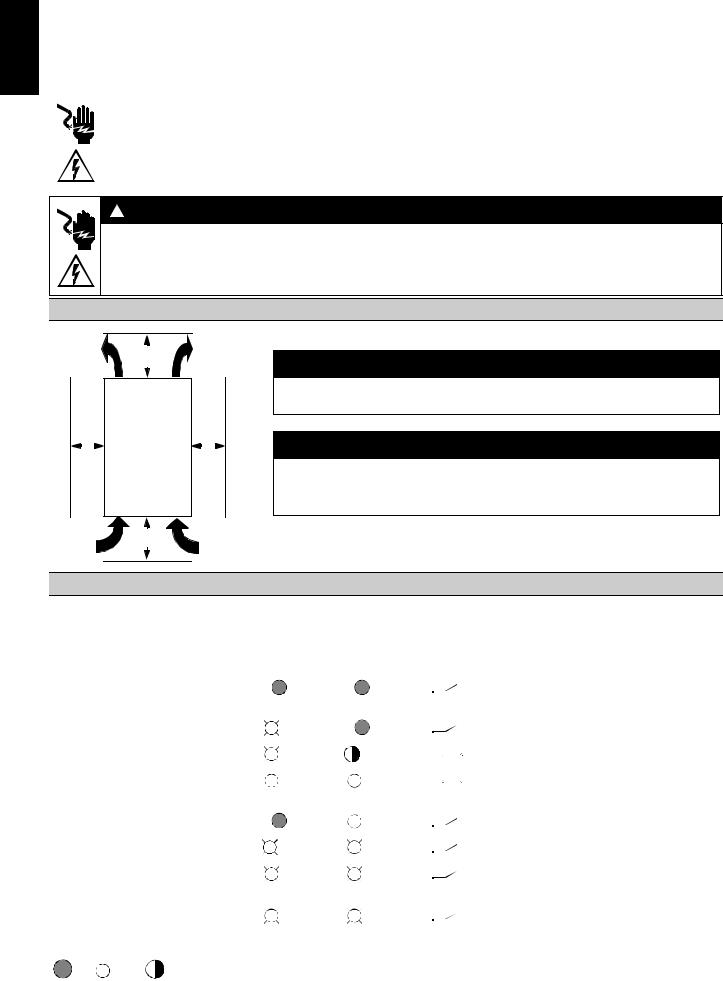
Einbauabstände in Einzelaufstellung (Dicht-an-dicht-Aufstellung siehe Sanftstarter-Handbuch)
≥ 60 mm [≥ 2.36 in]
1 3 5
a |
a |
|
|
|
|
2 4 6
≥ 40 mm ≥ 1.56 in]
ACHTUNG
Beachten Sie beim Einbau des Geräts die angegebenen Abstände, damit genügend Luft für Kühlung zirkulieren kann. Das Gerät wird von unten nach oben belüftet.
VORSICHT
Gefahr von Sachschäden.
Achten Sie darauf, dass keine Flüssigkeit, kein Staub oder leitender Gegenstand in den Sanftstarter gelangt.
a)3RW301; 3RW302: 15 mm [0.59 in] 3RW303; 3RW304: 30 mm [1.18 in]
Anzeigenübersicht
|
|
|
|
|
|
|
|
|
|
|
|
|
|
|
|
LED-Anzeigen 3RW30 |
Hilfskontakt |
|
|||||||||||
|
|
|
|
|
|
|
|
|
|
|
|
|
|
|
|
|
|
|
Sanftstarter |
|
|
|
|
|
|||||
|
|
|
|
|
|
|
|
|
|
|
|
|
|
DEVICE |
|
|
|
STATE / |
13 14 |
|
|
||||||||
3RW30 |
|
|
|
|
|
|
|
|
|
|
|
|
BYPASSED / FAILURE |
|
|
||||||||||||||
|
|
|
|
|
|
|
|
|
(rd / gn / ylw) |
|
(ON) |
|
|||||||||||||||||
|
|
|
|
|
|
|
|
|
|
|
|
|
|
|
|
|
|
|
|
|
|
(gn / rd) |
|
|
|
|
|
||
Us = 0 |
|
|
|
|
|
|
|
|
|
|
|
|
|
|
|
|
|
|
|
|
|
|
|
|
|
|
|
||
|
|
|
|
|
|
|
|
|
|
|
|
|
|
|
|
|
|
|
|
|
|
|
|
|
|
|
|
|
|
Betriebszustand |
|
|
|
IN |
|
|
|
|
|
|
|
|
|
|
|
|
|
|
|
|
|
|
|||||||
Aus |
|
|
|
|
|
|
|
0 |
|
|
|
|
|
|
|
gn |
|
|
|
|
|
|
|
|
|
|
|
||
|
|
|
|
|
|
|
|
|
|
|
|
|
|
|
|
|
|
|
|
|
|
|
|
|
|||||
|
|
|
|
|
|
|
|
|
|
|
|
|
|
|
|
|
|
|
|
|
|
|
|
|
|||||
|
|
|
|
|
|
|
|
|
|
|
|
|
|
|
|
|
|
|
|
|
|
|
|
|
|
|
|
|
|
Anlauf |
|
|
|
|
|
|
|
1 |
|
|
|
|
|
|
|
gn |
|
|
|
|
gn |
|
|
|
|
|
|||
|
|
|
|
|
|
|
|
|
|
|
|
|
|
|
|
|
|
|
|
|
|
|
|||||||
|
|
|
|
|
|
|
|
|
|
|
|
|
|
|
|
|
|
|
|
|
|
|
|||||||
Bypassed |
|
|
|
|
|
|
|
1 |
|
|
|
|
|
|
|
gn |
|
|
|
|
|
gn |
|
|
|
|
|
||
|
|
|
|
|
|
|
|
|
|
|
|
|
|
|
|
|
|
|
|
|
|
|
|
||||||
|
|
|
|
|
|
|
|
|
|
|
|
|
|
|
|
|
|
|
|
|
|
|
|
||||||
Fehler |
|
|
|
|
|
|
|
|
|
|
|
|
|
|
|
|
|
|
|
|
|
|
|
|
|
|
|
||
Versorgungsspannung Elektronik unzulässig |
|
|
|
|
|
|
|
|
|
|
|
|
rd |
|
|
|
|
|
|||||||||||
|
|
|
|
|
|
|
|
|
|
|
|
|
|
|
|
|
|||||||||||||
|
|
|
|
|
|
|
|
|
|
|
|
|
|
|
|
|
|||||||||||||
|
|
|
|
|
|
|
|
|
|
|
|
|
|
|
|
|
|
|
|
|
|
|
|
|
|
|
|
|
|
Bypass-Überlastung |
|
|
|
|
|
|
|
|
|
|
ylw |
|
|
|
|
|
rd |
|
|
|
|
|
|||||||
|
|
|
|
|
|
|
|
|
|
|
|
|
|
|
|
|
|
|
|
||||||||||
|
|
|
|
|
|
|
|
|
|
|
|
|
|
|
|
|
|
|
|
||||||||||
|
|
|
|
|
|
|
|
|
|
|
|
|
|
|
|
|
|
|
|
|
|
|
|
|
|
|
|
|
|
- fehlende Lastspannung |
|
|
|
|
|
|
|
|
gn |
|
|
|
|
|
rd |
|
|
|
|
|
|||||||||
|
|
|
|
|
|
|
|
|
|
|
|
|
|
|
|
|
|
||||||||||||
- Phasenausfall, fehlende Last |
|
|
|
|
|
|
|
|
|
|
|
|
|
|
|
|
|
|
|||||||||||
|
|
|
|
|
|
|
|
|
|
|
|
|
|
|
|
|
|
||||||||||||
|
|
|
|
|
|
|
|
|
|
|
|
|
|
|
|
|
|
|
|
||||||||||
|
|
|
|
|
|
|
|
|
|
|
|
|
|
|
|
|
|
|
|
|
|
|
|
|
|
|
|
|
|
Gerätefehler |
|
|
|
|
|
|
|
|
|
|
|
rd |
|
|
|
|
|
rd |
|
|
|
|
|
||||||
|
|
|
|
|
|
|
|
|
|
|
|
|
|
|
|
|
|
|
|
|
|||||||||
|
|
|
|
|
|
|
|
|
|
|
|
|
|
|
|
|
|
|
|
|
|||||||||
|
|
|
|
|
|
|
|
|
|
|
|
|
|
|
|
|
|
|
|
|
|
|
|
|
|
|
|
|
|
|
|
|
|
|
|
|
|
|
|
|
|
|
|
|
|
|
|
|
|
|
|
|
|
|
|
||||
Anzeige der LEDs |
|
|
|
|
|
|
|
|
|
|
|
|
|
|
|
|
|
|
|
|
|
||||||||
|
|
|
|
|
|
|
|
|
|
gn |
|
rd |
|
ylw |
|
|
|
|
|
|
|
|
|
||||||
|
|
|
|
|
|
|
|
|
|
|
|
|
|
|
|
|
|
|
|
|
|||||||||
|
|
|
|
|
|
|
|
|
|
= |
|
= |
|
|
|
|
|
= |
|
|
|
|
|
|
|
|
|
||
|
|
|
|
|
|
|
|
|
|
|
|
|
|
|
|
|
|
|
|
|
|
|
|
|
|||||
|
|
|
|
|
|
|
|
|
|
grün |
|
rot |
|
gelb |
|
|
|
|
|
|
|
|
|
||||||
aus |
|
|
ein |
|
blinkend |
|
|
|
|
|
|
|
|
|
|
|
|
||||||||||||
|
|
|
|
|
|
|
|
|
|
|
|
|
|
|
|
|
|
|
|
|
|
|
|
|
|
|
|
|
|
2 |
|
|
|
|
|
|
|
|
|
|
|
|
|
|
|
|
|
|
|
|
|
|
|
|
|
|
|
|
3ZX1012-0RW30-2DA1 |

HINWEIS
Dies ist ein Produkt für Umgebung A. In Haushaltsumgebung kann dieses Gerät unerwünschte Funkstörungen verursachen. In diesem Fall kann der Anwender verpflichtet sein, angemessene Maßnahmen durchzuführen.
Schnellinbetriebnahmeanleitung
VORSICHT
Gefahr von Sachschäden.
Anschluss an nicht belegte Klemmen ist unzulässig.
Einstellungsvorschlag |
|
Anlauf Parameter |
|
|
|
Startspannung % |
Anlaufzeit s |
||
Applikation |
|
5 |
||
|
|
|
||
|
|
|
10 |
|
|
40 |
100% |
0 |
20s |
|
|
|||
Förderband |
|
70 |
|
10 |
Rollenförderer |
|
60 |
|
10 |
Kompressor |
|
50 |
|
20 |
kleiner Ventilator |
|
40 |
|
20 |
Pumpe |
|
40 |
|
10 |
Hydraulikpumpe |
|
40 |
|
10 |
Rührwerk |
|
40 |
|
20 |
1. Verdrahtungskontrolle
-Steuerteil und
-Leistungsteil
2.Gerät parametrieren Sanftstartfunktion
-Anlaufzeit (s)
-Startspannung (%)
auf gewünschte Werte einstellen (siehe Tabelle Einstellungsvorschlag).
3. Spannungen im Steuer- |
|
|
Versorgungsspannung an |
und Hauptstromkreis über- |
|
|
Klemme A1 und A2 |
prüfen und zuschalten. |
|
|
kontrollieren. |
|
|
|
|
VORSICHT
Gefahr von Sachschäden.
Beachten Sie die Schalthäufigkeit (siehe techn. Daten Katalog). Eine zu hohe Schalthäufigkeit kann den Sanftstarter beschädigen.
1.Sanftstarter ausschalten (IN 1 -> 0).
2.Anlaufzeit erhöhen
(Poti nach rechts drehen)
Der Motor erreicht seine Nenndrehzahl
-erst nach der eingestellten Rampenzeit
-mit zu schnellem Momentenanstieg
-mit zu hohem
Anlaufstrom
|
|
|
|
|
|
|
|
|
|
|
|
|
|
|
|
|
|
1. Sanftstarter ausschalten |
|
1. Sanftstarter ausschalten |
|
1. Sanftstarter aus- |
|
|
|
||||||||||
(IN 1 -> 0). |
|
(IN 1 -> 0). |
|
schalten (IN 1 -> 0). |
|
|
|
||||||||||
2. Anlaufzeit reduzieren |
|
2. Startspannung erhöhen |
|
2. Startspannung |
|
|
|
||||||||||
(Poti nach links drehen) |
|
(Poti nach rechts drehen) |
|
reduzieren (Poti |
|
|
|
||||||||||
|
|
|
|
|
|
|
|
|
|
nach links drehen) |
|
|
|
||||
|
|
|
|
|
|
|
|
|
|
|
|
|
|
|
|
|
|
|
|
|
|
|
|
|
|
|
|
|
Der Motor |
|
|
||||
|
|
|
|
|
|
|
|
|
|
|
|
|
|||||
|
|
|
|
|
|
|
|
|
|
|
läuft mit |
nein |
|||||
|
|
Der Motor erreicht |
|
Der Motor |
|
|
|
Momenten- |
|||||||||
|
|
|
|
|
|
schlag an |
|
|
|
||||||||
|
|
seine Nenndrehzahl |
läuft nicht |
|
|
|
|
|
|
|
|
|
|
||||
|
|
- wesentlich schnel- |
sofort los |
|
|
|
|
|
|
|
|
|
|
||||
|
|
ler als in der einge- |
und brummt |
|
|
|
|
|
|
|
|
|
|
||||
|
|
stellten Rampenzeit |
|
|
|
|
|
|
|
|
|
|
|
|
|||
|
|
- gar nicht |
|
|
|
|
|
|
|
|
nein |
|
|
||||
|
|
(bleibt hängen) |
|
|
|
|
|
|
|
|
|
|
|||||
|
|
|
|
|
|
|
|
|
|
|
|
|
|
|
|
|
|
nein
ja
4. Sanftstarter einschalten (IN 0 -> 1)
ja
nein
ja
ja 
ja
Sanftstarter ausschalten (IN 1 -> 0)
<![endif]>Deutsch
3ZX1012-0RW30-2DA1 |
3 |

<![endif]>English
Soft starter 3RW301, 3RW302, 3RW303, 3RW304 |
English |
|
|
Read and understand these instructions before installing, operating, or maintaining the equipment.
|
|
|
|
|
|
|
! DANGER |
|
CAUTION |
|
|
|
|
|
|
|
Hazardous voltage. |
|
Reliable functioning of the equipment is only ensured with certified |
|
|
|
|
|
|
|
|
||
|
|
|
|
|
|
|
|
||
|
|
|
|
|
|
|
Will cause death or serious injury. |
|
|
|
|
|
|
|
|
|
|
||
|
|
|
|
|
|
|
Turn off and lock out all power supplying this |
|
components. |
|
|
|
|
|
|
|
device before working on this device. |
|
|
|
|
|
|
|
|
|
|
|
|
! DANGER
Hazardous voltage.
Will cause death or serious injury.
To avoid electrical shock or burn, do not touch soft starter terminals when voltage is applied to the soft starter. Output terminals will have voltage present even when soft starter is OFF.
Stand-alone installation spacings (see soft starter manual for side-by-side installation)
|
|
|
|
|
|
|
|
≥ 60 mm |
|
|
|
|
|
|
|
|
|
|
|
NOTICE |
|
|
|
|
|
|
|||||||||
|
|
|
|
|
|
|
|
|
|
|
|
|
|
|
|
|
|
|
|
|
|
|
|
|
|
|
|
|
|
|
|
||||
|
|
|
|
|
|
|
[≥ 2.36 in] |
|
|
|
|
|
|
|
|
|
|
|
Leave sufficient free space to ensure that the air required for cooling purposes can |
|
|||||||||||||||
|
|
|
|
|
|
|
|
|
|
|
|
|
|
|
|
|
|
|
|
|
|
|
|
||||||||||||
|
|
|
|
|
|
|
|
|
|
|
|
|
|
|
|
|
|
|
|
|
|
circulate from the bottom to the top of the unit. |
|
||||||||||||
|
|
|
|
|
1 |
3 |
|
|
5 |
|
|
|
|
|
|
||||||||||||||||||||
|
|
|
|
|
1 |
|
|
|
|
|
|
|
|
|
|
|
|
|
|
|
|
|
|
|
|
|
|
|
|
|
|
|
|
|
|
|
|
|
|
|
|
|
|
|
|
|
|
|
|
|
|
|
|
|
|
|
|
|
|
|
|
|
|
|
|
|
|
|
|
|
|
|
|
|
|
|
|
|
|
|
|
|
|
|
|
|
|
|
|
|
|
|
|
|
CAUTION |
|
|
|
|
|
|
||||||
|
|
|
|
|
|
|
|
|
|
|
|
|
|
|
|
|
|
|
|
|
|
|
|
|
|
|
|
|
|
||||||
|
|
a |
|
|
|
|
|
|
|
|
|
a |
|
|
|
|
|
|
Risk of damage to property. |
|
|
|
|
|
|
||||||||||
|
|
|
|
|
|
|
|
|
|
|
|
|
|
|
|
|
|
|
|
|
|
|
Ensure that no liquids, dust or conductive parts enter the soft starter. |
|
|||||||||||
|
|
|
|
|
|
|
|
|
|
|
|
|
|
|
|
|
|
|
|||||||||||||||||
|
|
|
|
|
|
|
|
|
|
|
|
|
|
|
|
|
|
|
|
|
|
|
|
|
|
|
|
|
|
|
|
|
|
||
|
|
|
|
|
|
|
|
|
|
|
|
|
|
|
|
|
|
|
|
|
|
|
|
|
|
|
|
|
|
|
|
|
|
|
|
|
|
|
|
|
|
|
|
|
|
|
|
|
|
|
|
|
|
|
|
|
|
|
NOTE |
|
|
|
|
|
|
||||||
|
|
|
|
|
|
|
|
|
|
|
|
|
|
|
|
|
|
|
|
|
|
|
|
|
|
|
|
|
|
|
|
||||
|
|
|
|
|
2 |
4 |
|
|
6 |
|
|
|
|
|
|
|
|
|
|
Surrounding air temperature - A rating assigned to open type equipment that refers |
|
||||||||||||||
|
|
|
|
|
|
|
|
|
|
|
|
|
|
|
|
|
to the maximum ambient temperature of air immediately surrounding the equipment |
|
|||||||||||||||||
|
|
|
|
|
|
|
|
|
|
|
|
|
|
|
|
|
|
|
|
|
|
|
|
||||||||||||
|
|
|
|
|
|
|
|
≥ 40 mm |
|
|
|
|
|
|
|
|
|
|
|
inside of the ultimate enclosure. |
|
||||||||||||||
|
|
|
|
|
|
|
|
≥ 1.56 in] |
|
|
|
|
|
|
|
|
|
|
|
|
|
|
|
|
|
|
|
|
|
|
|
|
|||
|
|
|
|
|
|
|
|
|
|
|
|
|
|
|
|
|
|
a) 3RW301; 3RW302: 15 mm [0.59 in] |
|||||||||||||||||
|
|
|
|
|
|
|
|
|
|
|
|
|
|
|
|
|
|
|
|
|
|
||||||||||||||
|
|
|
|
|
|
|
|
|
|
|
|
|
|
|
|
|
|
|
|
|
|
|
|
3RW303; 3RW304: 30 mm [1.18 in] |
|||||||||||
|
|
|
|
|
|
|
|
|
|
|
|
|
|
|
|
|
|
|
|
|
|
|
|
|
|
|
|
|
|
|
|
|
|
|
|
Display overview |
|
|
|
|
|
|
|
|
|
|
|
|
|
|
|
|
|
|
|
||||||||||||||||
|
|
|
|
|
|
|
|
|
|
|
|
|
|
|
|
|
|
|
|
|
|
|
|
|
|
|
|
|
|
|
|
|
|
|
|
|
|
|
|
|
|
|
|
|
|
|
|
|
|
|
|
|
|
|
|
|
|
|
LED displays on 3RW30 |
|
Auxiliary contact |
|
|
||||||||
|
|
|
|
|
|
|
|
|
|
|
|
|
|
|
|
|
|
|
|
|
|
|
|
|
Soft starter |
|
|
|
|
|
|
|
|||
|
|
|
|
|
|
|
|
|
|
|
|
|
|
|
|
|
|
|
|
|
DEVICE |
STATE / BYPASSED / |
|
13 14 |
|
|
|
||||||||
|
3RW30 |
|
|
|
|
|
|
|
|
|
|
|
|
|
|
FAILURE |
|
|
|
|
|||||||||||||||
|
|
|
|
|
|
|
|
|
|
|
|
|
(rd / gn / ylw) |
|
|
(ON) |
|
|
|||||||||||||||||
|
|
|
|
|
|
|
|
|
|
|
|
|
|
|
|
|
|
|
|
(gn / rd) |
|
|
|
|
|||||||||||
|
|
|
|
|
|
|
|
|
|
|
|
|
|
|
|
|
|
|
|
|
|
|
|
|
|
|
|
|
|
|
|
|
|||
|
Us = 0 |
|
|
|
|
|
|
|
|
|
|
|
|
|
|
|
|
|
|
|
|
|
|
|
|
|
|
|
|
|
|||||
|
|
|
|
|
|
|
|
|
|
|
|
|
|
|
|
|
|
|
|
|
|
|
|
|
|
|
|
|
|
|
|
|
|
|
|
|
Operating state |
|
|
|
|
|
|
IN |
|
|
|
|
|
|
|
|
|
|
|
|
|
|
|
|
|
||||||||||
|
OFF |
|
|
|
|
|
|
|
|
|
|
0 |
|
|
|
|
|
gn |
|
|
|
|
|
|
|
|
|
|
|
||||||
|
|
|
|
|
|
|
|
|
|
|
|
|
|
|
|
|
|
|
|
|
|
|
|
|
|
|
|||||||||
|
|
|
|
|
|
|
|
|
|
|
|
|
|
|
|
|
|
|
|
|
|
|
|
|
|
|
|||||||||
|
|
|
|
|
|
|
|
|
|
|
|
|
|
|
|
|
|
|
|
|
|
|
|
|
|
|
|
|
|
|
|
|
|
|
|
|
Start-up |
|
|
|
|
|
|
|
|
|
|
1 |
|
|
|
|
|
gn |
|
|
gn |
|
|
|
|
|
|
|
|||||||
|
|
|
|
|
|
|
|
|
|
|
|
|
|
|
|
|
|
|
|
|
|
|
|
|
|||||||||||
|
|
|
|
|
|
|
|
|
|
|
|
|
|
|
|
|
|
|
|
|
|
|
|
|
|||||||||||
|
Bypassed |
|
|
|
|
|
|
|
|
|
|
1 |
|
|
|
|
|
gn |
|
|
|
gn |
|
|
|
|
|
|
|
||||||
|
|
|
|
|
|
|
|
|
|
|
|
|
|
|
|
|
|
|
|
|
|
|
|
|
|
||||||||||
|
|
|
|
|
|
|
|
|
|
|
|
|
|
|
|
|
|
|
|
|
|
|
|
|
|
||||||||||
|
Error |
|
|
|
|
|
|
|
|
|
|
|
|
|
|
|
|
|
|
|
|
|
|
|
|
|
|
|
|
|
|||||
|
Supply voltage electronics invalid |
|
|
|
|
|
|
|
|
|
|
|
rd |
|
|
|
|
|
|
|
|||||||||||||||
|
|
|
|
|
|
|
|
|
|
|
|
|
|
|
|
|
|
|
|||||||||||||||||
|
|
|
|
|
|
|
|
|
|
|
|
|
|
|
|
|
|
|
|||||||||||||||||
|
|
|
|
|
|
|
|
|
|
|
|
|
|
|
|
|
|
|
|
|
|
|
|
|
|
|
|
|
|
|
|
|
|
|
|
|
Bypass overload |
|
|
|
|
|
|
|
|
|
|
|
|
ylw |
|
|
|
rd |
|
|
|
|
|
|
|
||||||||||
|
|
|
|
|
|
|
|
|
|
|
|
|
|
|
|
|
|
|
|
|
|
|
|||||||||||||
|
|
|
|
|
|
|
|
|
|
|
|
|
|
|
|
|
|
|
|
|
|
|
|||||||||||||
|
|
|
|
|
|
|
|
|
|
|
|
|
|
|
|
|
|
|
|
|
|
|
|
|
|
|
|
|
|
|
|
|
|
|
|
|
- Missing supply voltage |
|
|
|
|
|
|
|
|
|
|
|
|
gn |
|
|
|
rd |
|
|
|
|
|
|
|
||||||||||
|
|
|
|
|
|
|
|
|
|
|
|
|
|
|
|
|
|
|
|
|
|
|
|||||||||||||
|
- Phase failure, no load |
|
|
|
|
|
|
|
|
|
|
|
|
|
|
|
|
|
|
|
|
|
|
||||||||||||
|
|
|
|
|
|
|
|
|
|
|
|
|
|
|
|
|
|
|
|
|
|
|
|||||||||||||
|
|
|
|
|
|
|
|
|
|
|
|
|
|
|
|
|
|
|
|
|
|
|
|
|
|||||||||||
|
|
|
|
|
|
|
|
|
|
|
|
|
|
|
|
|
|
|
|
|
|
|
|
|
|
|
|
|
|
|
|
|
|
|
|
|
Device fault |
|
|
|
|
|
|
|
|
|
|
|
|
|
|
|
|
|
rd |
|
|
|
rd |
|
|
|
|
|
|
|
|||||
|
|
|
|
|
|
|
|
|
|
|
|
|
|
|
|
|
|
|
|
|
|
|
|
|
|
|
|
||||||||
|
|
|
|
|
|
|
|
|
|
|
|
|
|
|
|
|
|
|
|
|
|
|
|
|
|
|
|
||||||||
|
|
|
|
|
|
|
|
|
|
|
|
|
|
|
|
|
|
|
|
|
|
|
|
|
|
|
|
|
|
|
|
|
|
|
|
|
|
|
|
|
|
|
|
|
|
|
|
|
|
|
|
|
|
|
|
|
|
|
|
|
|
|
|
|
|
|
|
|
|
|
|
|
|
|
|
|
|
LED display |
|
|
|
|
|
|
|
|
|
|
|
|
|
|
|
|
|
|
|
|
|
|
|
|
|||||
|
|
|
|
|
|
|
|
|
|
|
|
|
|
|
|
|
|
gn |
|
|
|
rd |
ylw |
|
|
|
|
|
|
|
|
||||
|
|
|
|
|
|
|
|
|
|
|
|
|
|
|
|
|
|
|
|
|
|
|
|
|
|
|
|
|
|
||||||
|
|
|
|
|
|
|
|
|
|
|
|
|
|
|
|
|
= |
= |
|
= |
|
|
|
|
|
|
|
|
|
|
|||||
|
|
|
|
|
|
|
|
|
|
|
|
|
|
|
|
|
|
|
|
|
|
|
|
|
|
|
|
||||||||
|
|
|
|
|
|
|
|
|
|
|
|
|
|
|
|
|
|
green |
|
|
|
red |
yellow |
|
|
|
|
|
|
|
|
|
|||
|
OFF |
|
|
ON |
|
flashing |
|
|
|
|
|
|
|
|
|
||||||||||||||||||||
|
|
|
|
|
|
|
|
|
|
|
|
|
|
|
|
|
|
|
|
|
|
|
|
|
|
|
|
|
|
|
|
|
|
|
|
4 |
|
|
|
|
|
|
|
|
|
|
|
|
|
|
|
|
|
|
|
|
|
|
|
|
|
|
|
|
|
|
|
|
3ZX1012-0RW30-2DA1 |
||

NOTE
This is a product for environment A. When used in a household setting, this device can cause unwanted radio interference. In this case the user may be required to carry out appropriate measures to avoid such radio interference.
Quick commissioning instructions
CAUTION
Risk of damage to property.
Connection to an unassigned terminal is not permitted.
Suggested setting |
|
Startup parameters |
||
|
Start voltage % |
Starting time s |
||
Application |
|
5 |
||
|
|
|
||
|
|
|
10 |
|
|
40 |
100% |
0 |
20s |
|
|
|||
Conveyor belt |
|
70 |
|
10 |
Roller conveyor |
|
60 |
|
10 |
Compressor |
|
50 |
|
20 |
Small fan |
|
40 |
|
20 |
Pumps |
|
40 |
|
10 |
Hydraulic pump |
|
40 |
|
10 |
Stirrers |
|
40 |
|
20 |
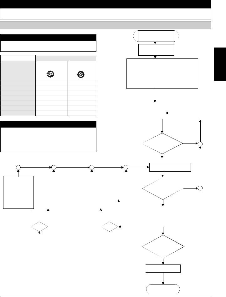
1. Wiring control
-Control part and
-Performance part
2.Configure device
Set the soft start function
-Starting time (s)
-Start voltage (%)
to the desired value
(see table for suggested settings).
3. Check and connect the |
|
|
|
Check the supply voltage on |
|
voltages in the control and |
|
|
|
terminals A1 and A2. |
|
main circuits. |
|
|
|
|
|
|
|
|
|
|
|
CAUTION |
|
|
|
|
|
|
|
|
|
|
|
|
|
|
|
|
|
|
|
|
|
|
|
|
|
|
|
|
|
|
|
|
|
|
|||||
Risk of damage to property. |
|
|
|
|
|
|
|
|
|
|
|
|
|
|
|
|
|
|
|
|
|
|
|
|
|
|
|
no |
|||||||||||
Please take the switching frequency into consideration |
|
|
|
|
|
|
|
|
|
|
|
|
|
|
|
|
|
|
|
|
|
|
|
||||||||||||||||
(see techn. data catalog). |
|
|
|
|
|
|
|
|
|
|
|
|
|
|
|
|
|
|
|
|
|
|
|
|
|
|
|
|
|
||||||||||
If the switching frequency is too high, it could damage the |
|
|
|
|
|
|
|
|
|
|
|
|
yes |
|
|
|
|
|
|
|
|
|
|
||||||||||||||||
|
|
|
|
|
|
|
|
|
|
|
|
|
|
|
|
|
|
|
|
|
|||||||||||||||||||
soft starter. |
|
|
|
|
|
|
|
|
|
|
|
|
|
|
|
|
|
|
|
|
|
|
|
|
|
|
|
|
|
|
|||||||||
|
|
|
|
|
|
|
|
|
|
|
|
|
|
|
|
|
|
|
|
|
|
|
|
|
|
|
|
|
|
|
|
|
|
|
|
|
|
|
|
|
|
|
|
|
|
|
|
|
|
|
|
|
|
|
|
|
|
|
|
|
|
|
|
|
|
|
|
|
|
|
|
|
|
|
|
|
|
|
|
|
|
|
|
|
|
|
|
|
|
|
|
|
|
|
|
|
|
|
|
|
|
|
|
|
|
|
|
|
|
|
|
|
|
|
|
|
|
|
|
|
|
|
|
|
|
|
|
|
|
|
|
|
|
|
|
|
|
|
|
|
|
|
|
|
|
|
|
4. Switch soft starter |
|||||||||||
|
|
|
|
|
|
|
|
|
|
|
|
|
|
|
|
|
|
|
|
|
|
|
|
|
|
|
|
on (IN 0 -> 1) |
|
|
|
||||||||
|
|
|
|
|
|
|
|
|
|
|
|
|
|
|
|
|
|
|
|
|
|
|
|
|
|
|
|
|
yes |
|
|
|
|
|
|
||||
|
|
|
|
|
|
|
|
|
|
|
|
|
|
|
|
|
|
|
|
|
|
|
|
|
|
|
|
|
|
||||||||||
|
1. Switch soft starter |
|
1. Switch off soft starter |
|
1. Switch off soft starter |
|
1. Switch soft starter off |
|
|
|
|
|
|
|
|
|
|
|
|
|
|
|
|||||||||||||||||
|
off (IN 1 -> 0). |
|
(IN 1 -> 0). |
|
(IN 1 -> 0). |
|
(IN 1 -> 0). |
|
|
|
|
|
|
|
|
|
|
|
|
|
|
no |
|||||||||||||||||
|
2. Increase starting |
|
2. Reduce starting time. |
|
2. Increase start voltage. |
|
2. Reduce start voltage. |
|
|
|
|
|
|
|
|
|
|
|
|
|
|
||||||||||||||||||
|
time. (Turn potentio- |
|
(Turn potentiometer anti- |
|
(Turn potentiometer clock- |
|
(Turn potentiometer |
|
|
|
|
|
|
|
|
|
|
|
|
|
|
|
|||||||||||||||||
|
|
|
|
|
|
|
|
|
|
|
|
|
|
|
|
|
|
|
|||||||||||||||||||||
|
meter clockwise) |
|
clockwise) |
|
wise) |
|
anti-clockwise) |
|
|
|
|
|
|
|
|
|
|
|
|
|
|
|
|||||||||||||||||
|
|
|
|
|
|
|
|
|
|
|
|
|
|
|
|
|
|
|
|
|
|
|
|
|
|
|
|
|
|
|
|
|
|
|
|
|
|
|
|
The motor rea- |
|
|
The motor reaches |
|
The motor |
|
|
|
The motor starts |
|
|
|
|
yes |
|
|
|
|
|||||||||||||||||||||
|
|
|
|
|
|
|
|
|
|
|
|
|
|
||||||||||||||||||||||||||
|
|
|
|
|
|
|
|||||||||||||||||||||||||||||||||
ches its nominal |
|
|
its nominal rotational |
|
hums and |
|
|
|
with a sudden |
|
|
|
|
|
|
|
|
|
|
|
|
|
|
|
|||||||||||||||
rotational speed |
|
|
speed |
|
does not start |
|
|
|
increase in |
|
|
|
|
|
|
|
|
|
|
|
|
|
|
|
|||||||||||||||
- only after the |
|
|
- significantly faster |
|
immediately |
|
|
|
torque |
no |
|||||||||||||||||||||||||||||
specified ramp |
|
|
than in the specified |
|
|
|
|
|
|
|
|
|
|
|
|
|
|
||||||||||||||||||||||
time |
|
|
|
ramp time |
|
|
|
|
|
|
|
|
|
|
|
|
|
|
|
|
|
|
|
|
|
|
|
|
|
|
|
|
|
||||||
- with too fast of an |
|
- not at all |
|
|
|
|
|
|
|
|
|
|
|
|
|
|
|
|
|
|
|
|
|
|
|
|
|
|
|
|
|
||||||||
increase in torque |
|
(motor stuck) |
|
|
|
|
|
|
|
|
|
|
|
|
|
|
|
|
|
|
yes |
|
|
|
|
|
|
|
|||||||||||
|
|
|
|
|
|
|
|
|
|
|
|
|
|
|
|
|
|
|
|
|
|
|
|
|
|
||||||||||||||
- with an excessive |
|
|
|
|
|
|
|
|
|
|
|
|
|
|
|
|
|
|
|
|
|
|
|
|
|
|
|
||||||||||||
starting current |
|
|
|
|
|
|
|
|
|
|
|
|
|
|
|
|
|
|
|
|
|
|
|
|
|
|
|
|
|
|
|
|
|
|
|||||
|
|
|
|
|
|
|
|
|
|
|
|
|
|
|
|
|
|
|
|
|
|
|
|
no |
|
|
|
|
|
|
|
|
|
|
|
|
|
|
|
|
|
|
|
|
|
|
|
|
|
|
|
|
|
|
|
|
|
|
|
|
|
|
|
|
|
|
|
|
yes |
|
|
|
|
|
|||||
|
|
|
|
|
|
|
|
|
|
|
|
|
|
|
|
|
|
|
|
|
|
|
|
|
|
|
|
|
|
|
|||||||||
|
|
|
|
|
|
|
|
|
|
|
|
|
|
|
|
|
|
|
|
|
|
|
|
|
|
|
|
|
|
|
|
|
|
|
|
|
|
||
|
|
|
|
|
|
|
|
|
|
|
|
|
|
|
|
|
|
|
|
|
|
|
|
|
|
|
|
|
|
|
|
|
|
|
|
|
|
|
|
|
|
|
|
|
|
|
|
|
|
|
|
|
|
|
|
|
|
|
|
|
|
|
|
|
|
|
|
|
Switch soft starter |
||||||||||
|
|
|
|
|
|
|
|
|
|
|
|
|
|
|
|
|
|
|
|
|
|
|
|
|
|
|
|
|
off (IN 1 -> 0) |
|
|
||||||||
|
|
|
|
|
|
|
|
|
|
|
|
|
|
|
|
|
|
|
|
|
|
|
|
|
|
|
|
|
|
|
|
|
|
|
|
|
|
|
|
<![endif]>English
3ZX1012-0RW30-2DA1 |
5 |

<![endif]>Français
Démarreur progressif 3RW301, 3RW302, 3RW303, 3RW304 |
Français |
|
|
Ne pas installer, utiliser ou intervenir sur cet équipement avant d'avoir lu et assimilé les présentes instructions et notamment les
conseils de sécurité et mises en garde qui y figurent.
! DANGER
Tension dangereuse.
Danger de mort ou risque de blessures graves.
Mettre hors tension avant d’intervenir sur l’appareil.
PRUDENCE
Le fonctionnement sûr de l'appareil n'est garanti qu'avec des composants certifiés.
! DANGER
Tension dangereuse.
Danger de mort ou risque de blessures graves.
Pour éviter tout risque d'électrocution ou de brûlures, ne pas toucher les bornes du démarreur lorsque celui-ci est sous tension. Les bornes de sortie sont sous tension même lorsque le démarreur est hors tension.
Distances de montage pour installation séparée
(installation juxtaposée, voir le manuel système Démarreurs progressifs)
≥ 60 mm [≥ 2.36 in]
1 3 5
a |
a |
|
|
|
|
2 4 6
≥ 40 mm ≥ 1.56 in]
IMPORTANT
Respecter un espace libre suffisant pour assurer la circulation de l’air nécessaire au refroidissement, qui se fait par ventilation du bas vers le haut.
PRUDENCE
Risque de dommages matériels.
Veuillez à ce que ni liquide, ni poussière ou objet conducteur ne puisse pénétrer dans le démarreur progressif.
a) 3RW301; 3RW302: 15 mm [0.59 in] 3RW303; 3RW304: 30 mm [1.18 in]
Vue d’ensemble des affichages
|
|
|
|
|
|
|
|
|
|
|
|
|
LED de signalisation 3RW30 |
Contact auxiliaire |
|
||||||||||||
|
|
|
|
|
|
|
|
|
|
|
|
|
|
|
|
Démarreur progressif |
|
|
|
|
|
||||||
|
|
|
|
|
|
|
|
|
|
|
|
|
DEVICE |
|
|
STATE / |
13 14 |
|
|
||||||||
3RW30 |
|
|
|
|
|
|
|
|
BYPASSED / FAILURE |
|
|
||||||||||||||||
|
|
|
|
|
(rd / gn / ylw) |
|
(ON) |
|
|||||||||||||||||||
|
|
|
|
|
|
|
|
|
|
|
|
(gn / rd) |
|
|
|||||||||||||
|
|
|
|
|
|
|
|
|
|
|
|
|
|
|
|
|
|
|
|
|
|
|
|
|
|||
Us = 0 |
|
|
|
|
|
|
|
|
|
|
|
|
|
|
|
|
|
|
|
|
|
|
|
||||
|
|
|
|
|
|
|
|
|
|
|
|
|
|
|
|
|
|
|
|
|
|
|
|
|
|
|
|
Etat de fonctionnement |
IN |
|
|
|
|
|
|
|
|
|
|
|
|
|
|
|
|
|
|
||||||||
Arrêté |
|
|
|
0 |
|
|
|
|
|
|
|
|
gn |
|
|
|
|
|
|
|
|
|
|
||||
|
|
|
|
|
|
|
|
|
|
|
|
|
|
|
|
|
|
|
|
|
|||||||
|
|
|
|
|
|
|
|
|
|
|
|
|
|
|
|
|
|
|
|
|
|||||||
|
|
|
|
|
|
|
|
|
|
|
|
|
|
|
|
|
|
|
|
|
|
|
|
|
|
|
|
Démarrage |
|
|
|
1 |
|
|
|
|
|
|
|
|
gn |
|
|
|
gn |
|
|
|
|
|
|||||
|
|
|
|
|
|
|
|
|
|
|
|
|
|
|
|
|
|
|
|||||||||
|
|
|
|
|
|
|
|
|
|
|
|
|
|
|
|
|
|
|
|||||||||
|
|
|
|
|
|
|
|
|
|
|
|
|
|
|
|
|
|
|
|
|
|
|
|
|
|
|
|
Bypassed |
|
|
|
1 |
|
|
|
|
|
|
|
|
gn |
|
|
|
|
gn |
|
|
|
|
|
||||
|
|
|
|
|
|
|
|
|
|
|
|
|
|
|
|
|
|
|
|
||||||||
|
|
|
|
|
|
|
|
|
|
|
|
|
|
|
|
|
|
|
|
||||||||
Défauts |
|
|
|
|
|
|
|
|
|
|
|
|
|
|
|
|
|
|
|
|
|
|
|
||||
Tension d’alimentation de l’électronique incorrecte |
|
|
|
|
|
|
|
|
|
|
|
|
rd |
|
|
|
|
|
|||||||||
|
|
|
|
|
|
|
|
|
|
|
|
|
|
|
|
|
|||||||||||
|
|
|
|
|
|
|
|
|
|
|
|
|
|
|
|
|
|||||||||||
|
|
|
|
|
|
|
|
|
|
|
|
|
|
|
|
|
|
|
|
|
|
|
|
|
|
|
|
Surcharge bypass |
|
|
|
|
|
|
|
|
|
|
|
|
ylw |
|
|
|
|
rd |
|
|
|
|
|
||||
|
|
|
|
|
|
|
|
|
|
|
|
|
|
|
|
|
|
|
|
|
|||||||
|
|
|
|
|
|
|
|
|
|
|
|
|
|
|
|
|
|
|
|
|
|||||||
|
|
|
|
|
|
|
|
|
|
|
|
|
|
|
|
|
|
|
|
|
|
|
|
|
|
|
|
- tension de charge manque |
|
|
|
|
|
|
|
|
|
gn |
|
|
|
|
rd |
|
|
|
|
|
|||||||
|
|
|
|
|
|
|
|
|
|
|
|
|
|
|
|
|
|
||||||||||
- coupure de phase, charge non raccordée |
|
|
|
|
|
|
|
|
|
|
|
|
|
|
|
|
|||||||||||
|
|
|
|
|
|
|
|
|
|
|
|
|
|
|
|
||||||||||||
|
|
|
|
|
|
|
|
|
|
|
|
|
|
|
|
|
|
||||||||||
|
|
|
|
|
|
|
|
|
|
|
|
|
|
|
|
|
|
|
|
|
|
|
|
|
|
|
|
Défaut sur l’appareil |
|
|
|
|
|
|
|
|
|
|
|
|
rd |
|
|
|
|
rd |
|
|
|
|
|
||||
|
|
|
|
|
|
|
|
|
|
|
|
|
|
|
|
|
|
|
|
|
|||||||
|
|
|
|
|
|
|
|
|
|
|
|
|
|
|
|
|
|
|
|
|
|||||||
|
|
|
|
|
|
|
|
|
|
|
|
|
|
|
|
|
|
|
|
|
|
|
|
|
|
|
|
|
|
|
|
|
|
|
|
|
|
|
|
|
|
|
|
|
|
|
|
|
|
|
|
|
|
||
Affichage des LED |
|
|
|
|
|
|
|
|
|
|
|
|
|
|
|
|
|
|
|
|
|
||||||
|
|
|
|
|
|
|
|
gn |
|
rd |
|
|
|
|
ylw |
|
|
|
|
|
|
|
|
|
|
||
|
|
|
|
|
|
|
|
|
|
|
|
|
|
|
|
|
|
|
|
|
|
|
|||||
|
|
|
|
|
|
|
|
= |
|
= |
|
|
|
|
= |
|
|
|
|
|
|
|
|
|
|
||
|
|
|
|
|
|
|
|
|
|
|
|
|
|
|
|
|
|
|
|
|
|
|
|||||
|
|
|
|
|
|
|
|
verte |
|
rouge |
|
|
|
|
jaune |
|
|
|
|
|
|
|
|
|
|
||
éteinte |
allumée |
clignotante |
|
|
|
|
|
|
|
|
|
|
|
|
|
|
|||||||||||
|
|
|
|
|
|
|
|
|
|
|
|
|
|
|
|
|
|
|
|
|
|
|
|
|
|
|
|
6 |
3ZX1012-0RW30-2DA1 |
NOTE
Ceci est un produit pour environnement A. Utilisé dans un cadre domestique, cet appareil peut causer des interférences radio indésirables. Dans ce cas, l’utilisateur peut être obligé de prendre les mesures nécessaires pour éviter de telles interférences.
Instructions de mise en service rapide
PRUDENCE
Risque de dommages matériels.
Un raccordement aux bornes libres est inadmissible.
Proposition de réglage |
|
Paramètres de démarrage |
|||
|
|
Tension |
Temps démarrage s |
||
Application |
démarrage % |
||||
|
5 |
||||
|
|
|
|||
|
|
|
|
10 |
|
|
40 |
100% |
0 |
20s |
|
|
|
||||
Convoyeur |
|
70 |
|
10 |
|
Convoyeur à rouleaux |
|
60 |
|
10 |
|
Compresseur |
|
50 |
|
20 |
|
Petit ventilateur |
|
40 |
|
20 |
|
Pompe |
|
40 |
|
10 |
|
Pompe hydraulique |
|
40 |
|
10 |
|
Malaxeur |
|
40 |
|
20 |
|
1. Contrôle du câblage
-bloc de commande et
-bloc de puissance
2.Paramétrage de l’appareil Fonction démarreur progressif
-temps démarrage (s)
-tension de démarrage (%)
à régler sur les valeurs souhaitées (voir le tableau Proposition de réglage).
3. Contrôler et mettre en |
|
|
Contrôler la tension |
circuit les tensions dans le |
|
|
d’alimentation aux bornes |
circuit principal et de com- |
|
|
A1 et A2. |
mande. |
|
|
|
|
|
|
|
|
|
|
|
PRUDENCE
Risque de dommages matériels.
Veuillez respecter la fréquence de manœuvres
(voir les caractéristiques techniques dans le catalogue). Une fréquence de manœuvres trop élevée risque d’endommager le démarreur progressif.
non
oui 
1.Arrêt du démarreur progressif (IN 1 -> 0).
2.Allonger le temps de démarrage (rotation du
potentiomètre à droite)
Le moteur atteint sa  vitesse nominale
-seulement après le temps rampe réglé
-avec une montée de couple trop rapide
-avec un courant de démarrage trop fort
|
|
|
|
|
|
|
|
|
|
|
|
|
|
|
|
|
|
1. Arrêt du démarreur |
|
1. Arrêt du démarreur |
|
1. Arrêt du démarreur |
|
|
|||||||||||
progressif (IN 1 -> 0). |
|
progressif (IN 1 -> 0). |
|
progressif (IN 1 -> 0). |
|
|
|||||||||||
2. Réduire le temps de |
|
2. Augmenter la tension de |
|
2. Réduire la tension |
|
|
|
||||||||||
démarrage (rotation du |
|
démarrage (rotation du |
|
de démarrage (rota- |
|
|
|
||||||||||
potentiomètre à gauche) |
|
potentiomètre à droite) |
|
tion du potentiomètre |
|
|
|||||||||||
|
|
|
|
|
|
|
|
|
|
à gauche) |
|
|
|
||||
|
|
|
|
|
|
|
|
|
|
|
Le moteur |
|
|
|
|||
|
|
|
|
|
|
|
|
|
|
|
|
|
|
||||
|
|
|
|
|
|
|
|
|
|
|
démarre |
|
|
|
|||
|
|
|
|
|
|
|
|
|
|
|
|
||||||
|
|
Le moteur atteint sa |
Le moteur ne |
|
|
|
avec choc de |
|
|
|
|||||||
|
|
|
|
|
couple |
non |
|||||||||||
|
|
vitesse nominale |
|
démarre pas |
|
|
|
||||||||||
|
|
- beaucoup plus |
|
immédiate- |
|
|
|
|
|
|
|
|
|
|
|||
|
|
rapidement que le |
|
ment et ronfle |
|
|
|
|
|
|
|
|
|
|
|||
|
|
temps rampe réglé |
|
|
|
|
|
|
|
|
|
|
|
|
|
||
|
|
- pas du tout |
|
|
|
|
|
|
|
|
|
|
|
|
|
||
|
|
(s'arrête) |
|
|
|
|
|
|
|
|
|
|
|
|
|
||
|
|
|
|
|
|
|
|
|
|
|
|
|
non |
|
|
|
|
|
|
|
|
|
|
|
|
|
|
|
|
|
|
|
|
|
|
4. Mettre en marche le démarreur progressif (IN 0 -> 1)
oui
non
oui
oui
oui
Arrêt du démarreur progressif (IN 1 -> 0)
<![endif]>Français
3ZX1012-0RW30-2DA1 |
7 |
 Loading...