


11-2AA0
Siemens 11-2AA0, 12-5AA0, 15-5AA0, 17-5AA0, 21-1BA0 Operating Instruction
...
MICROMASTER
Operating Instructions Issue A2
User Documentation


V
Overview
1
MICROMASTER 420
Operating Instructions
User Documentation
Installation
Commissioning
Using the
MICROMASTER 420
System Parameters
Troubleshooting
MICROMASTER 420
Specifications
2
3
4
5
6
7
alid for Release
Inverter Type Control Version
MICROMASTER 420 October 2000
Supplementary
Information
Appendices
Index
8
A
B
C
D
E
F
G
H
Issue: A2

Further information is available on the Internet under:
g
http://www.siemens.de/micromaster
Approved Siemens Quality for Software and Training
is to DIN ISO 9001, Reg. No. 2160-01
The reproduction, transmission or use of this document, or its
contents is not permitted unless authorized in writing.
Offenders will be liable for damages. All rights including rights
created by patent grant or registration of a utility model or
design are reserved.
© Siemens AG 2000. All Rights Reserved.
MICROMASTER® is a registered trademark of Siemens.
Order Number. 6SE6400-5AA00-0BP0
Printed in the United Kin
4 MICROMASTER 420 Operating Instructions
dom
Other functions not described in this document may be
available. However, this fact shall not constitute an obligation
to supply such functions with a new control, or when
servicing.
We have checked that the contents of this document
correspond to the hardware and software described. There
may be discrepancies nevertheless, and no guarantee can be
given that they are completely identical. The information
contained in this document is reviewed regularly and any
necessary changes will be included in the next edition. We
welcome suggestions for improvement.
Siemens handbooks are printed on chlorine-free paper that
has been produced from managed sustainable forests. No
solvents have been used in the printing or binding process.
Document subject to change without prior notice.
Siemens-Aktiengesellschaft.
6SE6400-5AA00-0BP0

FOREWORD International English
Foreword
User Documentation
Warning
!
Before installing and commissioning, you must read the safety instructions and
warnings carefully and all the warning labels attached to the equipment. Make
sure that the warning labels are kept in a legible condition and replace missing or
damaged labels.
MICROMASTER documentation is structured within three distinct levels:
♦ Getting Started Guide
The Getting Started Guide is designed to give you quick access to all the basic
information required to install and set up your MICROMASTER 420 for operation.
♦ Operating Instructions
The Operating Instructions provide detailed information for installation and operation
of your MICROMASTER 420. The Operating Instructions also provide detailed
descriptions of the parameters available for customizing the functions of the
MICROMASTER 420.
♦ Reference Manual
The Reference Manual contains in-depth information on all technical issues relating
to the MICROMASTER 420 Inverter.
For more detailed information on MICROMASTER 420 publications and for information
about other publications in the MICROMASTER range please contact your local Siemens
office or refer to our Web Site: http://www.siemens.de/micromaster.
MICROMASTER 420 Operating Instructions 5
6SE6400-5AA00-0BP0

International English FOREWORD
Definitions and Warnings
Danger
!
!
!
For the purpose of this documentation and the product warning labels, "Danger"
indicates that death, severe personal injury or substantial damage to property will
result if proper precautions are not taken.
Warning
For the purpose of this documentation and the product warning labels, "Warning"
indicates that death, severe personal injury or substantial damage to property can
result if proper precautions are not taken.
Caution
For the purpose of this documentation and the product warning labels, "Caution"
indicates that minor personal injury or material damage can result if proper
precautions are not taken.
Note
For the purpose of this documentation, "Note" indicates important information
relating to the product or highlights part of the documentation for special
attention.
Qualified personnel
For the purpose of this Instruction Manual and product labels, a "Qualified
person" is someone who is familiar with the installation, mounting, start-up and
operation of the equipment and the hazards involved.
He or she must have the following qualifications:
1. Trained and authorized to energize, de-energize, clear, ground and tag
circuits and equipment in accordance with established safety procedures.
2. Trained in the proper care and use of protective equipment in accordance
with established safety procedures.
3. Trained in rendering first aid.
Use for intended purpose only
The equipment may be used only for the application stated in the manual and only in
conjunction with devices and components recommended and authorized by Siemens.
Contact address
Should any questions or problems arise while reading this manual, please contact the
Siemens office concerned using the form provided at the back this manual.
6 MICROMASTER 420 Operating Instructions
6SE6400-5AA00-0BP0

FOREWORD International English
Safety Instructions
The following Warnings, Cautions and Notes are provided for your safety and as a means
of preventing damage to the product or components in the machines connected. This
section lists Warnings, Cautions and Notes, which apply generally when handling
MICROMASTER 420 Inverters, classified as General, Transport & Storage,
Commissioning, Operation, Repair and Dismantling & Disposal.
Specific Warnings, Cautions and Notes that apply to particular activities are listed at
the beginning of the relevant chapters and are repeated or supplemented at critical points
throughout these chapters.
Please read the information carefully, since it is provided for your personal safety
and will also help prolong the service life of your MICROMASTER 420 Inverter and
the equipment you connect to it.
General
!
!
Warnings
♦ This equipment contains dangerous voltages and controls potentially
dangerous rotating mechanical parts. Non-compliance with Warnings or
failure to follow the instructions contained in this manual can result in loss of
life, severe personal injury or serious damage to property.
♦ Only suitable qualified personnel should work on this equipment, and only
after becoming familiar with all safety notices, installation, operation and
maintenance procedures contained in this manual. The successful and safe
operation of this equipment is dependent upon its proper handling,
installation, operation and maintenance.
♦ Risk of electric shock. The DC link capacitors remain charged for five minutes
after power has been removed. It is not permissible to open the
equipment until 5 minutes after the power has been removed.
♦ HP ratings are based on the Siemens 1LA motors and are given for
guidance only, they do not necessarily comply with UL or NEMA HP
ratings.
Caution
♦ Children and the general public must be prevented from accessing or
approaching the equipment!
♦ This equipment may only be used for the purpose specified by the
manufacturer. Unauthorized modifications and the use of spare parts and
accessories that are not sold or recommended by the manufacturer of the
equipment can cause fires, electric shocks and injuries.
Notes
♦ Keep these operating instructions within easy reach of the equipment and
make them available to all users
♦ Whenever measuring or testing has to be performed on live equipment, the
regulations of Safety Code VBG 4.0 must be observed, in particular § 8
“Permissible Deviations when Working on Live Parts”. Suitable electronic
tools should be used.
♦ Before installing and commissioning, please read these safety instructions
and warnings carefully and all the warning labels attached to the equipment.
Make sure that the warning labels are kept in a legible condition and replace
missing or damaged labels
MICROMASTER 420 Operating Instructions 7
6SE6400-5AA00-0BP0

International English FOREWORD
Transport & Storage
!
!
Commissioning
!
Warnings
♦ Correct transport, storage, erection and mounting, as well as careful
Caution
♦ Protect the inverter against physical shocks and vibration during transport
Warnings
♦ Work on the device/system by unqualified personnel or failure to comply
♦ Only permanently-wired input power connections are allowed. This
♦ If a Residual Current-operated protective Device (RCD) is to be used, it must
♦ Machines with a three phase power supply, fitted with EMC filters, must not
♦ The following terminals can carry dangerous voltages even if the inverter is
♦ This equipment must not be used as an ‘emergency stop mechanism’ (see
operation and maintenance are essential for proper and safe operation of the
equipment.
and storage. Also be sure to protect it against water (rainfall) and excessive
temperatures (see table on page 101).
with warnings can result in severe personal injury or serious damage to
material. Only suitably qualified personnel trained in the setup, installation,
commissioning and operation of the product should carry out work on the
device/system.
equipment must be grounded (IEC 536 Class 1, NEC and other applicable
standards).
be an RCD type B.
be connected to a supply via an ELCB (Earth Leakage Circuit-Breaker - see
DIN VDE 0160, section 5.5.2 and EN50178 section 5.2.11.1).
inoperative:
- the power supply terminals L/L1, N/L2, L3.
- the motor terminals U, V, W, DC+, DC-
EN 60204, 9.2.5.4)
!
8 MICROMASTER 420 Operating Instructions
Caution
The connection of power, motor and control cables to the inverter must be carried
out as shown in Figure 2-4 on page 25, to prevent inductive and capacitive
interference from affecting the correct functioning of the inverter.
6SE6400-5AA00-0BP0

FOREWORD International English
Operation
!
Warnings
♦ MICROMASTERS operate at high voltages.
♦ When operating electrical devices, it is impossible to avoid applying
hazardous voltages to certain parts of the equipment.
♦ Emergency Stop facilities according to EN 60204 IEC 204 (VDE 0113) must
remain operative in all operating modes of the control equipment. Any
disengagement of the Emergency Stop facility must not lead to uncontrolled
or undefined restart.
♦ Wherever faults occurring in the control equipment can lead to substantial
material damage or even grievous bodily injury (i.e. potentially dangerous
faults), additional external precautions must be taken or facilities provided to
ensure or enforce safe operation, even when a fault occurs (e.g. independent
limit switches, mechanical interlocks, etc.).
♦ Certain parameter settings may cause the inverter to restart automatically
after an input power failure.
♦ This equipment is capable of providing internal motor overload protection in
accordance with UL508C section 42. Refer to P0610 (level 3) and P0335, I
is ON by default. Motor overload protection can also be provided using an
external PTC via a digital input.
♦ This equipment is suitable for use in a circuit capable of delivering not more
than 10,000 symmetrical amperes (rms), for a maximum voltage of 230/460V
when protected by a time delay fuse (see Table on page 102).
♦ This equipment must not be used as an ‘emergency stop mechanism’ (see
EN 60204, 9.2.5.4)
2
T
Repair
!
Warnings
♦ Repairs on equipment may only be carried out by Siemens Service, by
repair centers authorized by Siemens or by qualified personnel who are
thoroughly acquainted with all the warnings and operating procedures
contained in this manual.
♦ Any defective parts or components must be replaced using parts contained in
the relevant spare parts list.
♦ Disconnect the power supply before opening the equipment for access
Dismantling & Disposal
Notes
♦ The inverter’s packaging is re-usable. Retain the packaging for future use or
return it to the manufacturer.
♦ Easy-to-release screw and snap connectors allow you to break the unit down
into its component parts. You can then re-cycle these component parts,
dispose of them in accordance with local requirements or return them to
the manufacturer.
MICROMASTER 420 Operating Instructions 9
6SE6400-5AA00-0BP0

International English FOREWORD
10 MICROMASTER 420 Operating Instructions
6SE6400-5AA00-0BP0

Table of Contents
1 Overview.................................................................................................................. 15
1.1 The MICROMASTER 420........................................................................................... 16
1.2 Features .....................................................................................................................16
2 Installation ...............................................................................................................17
2.1 General....................................................................................................................... 18
2.2 Ambient operating conditions ..................................................................................... 19
2.3 Mechanical Installation ............................................................................................... 20
2.4 Electrical Installation................................................................................................... 21
3 Commissioning ........................................................................................................ 27
3.1 Front Panels for the MICROMASTER 420 ................................................................. 29
3.2 General operation....................................................................................................... 34
4 Using the MICROMASTER 420 .............................................................................. 37
4.1 Frequency Setpoint.....................................................................................................38
4.2 Command Sources (P0700) ....................................................................................... 38
4.3 OFF and braking Functions ........................................................................................ 39
4.4 Control Modes (P1300)...............................................................................................40
4.5 Faults and warnings....................................................................................................40
5 System Parameters ................................................................................................. 41
5.1 Overview of MICROMASTER System Parameters .................................................... 42
5.2 Introduction to MICROMASTER System Parameters................................................. 43
5.3 System Parameters and Definitions ........................................................................... 48
6 Troubleshooting....................................................................................................... 91
6.1 Troubleshooting with the Status Display Panel........................................................... 92
6.2 Troubleshooting with the Basic Operator Panel.......................................................... 93
6.3 MICROMASTER 420 fault codes ...............................................................................94
7 MICROMASTER 420 Specifications ....................................................................... 99
8 Supplementary Information ................................................................................... 103
8.1 Available options ......................................................................................................104
8.2 Electro-Magnetic Compatibility (EMC)...................................................................... 104
MICROMASTER 420 Operating Instructions 11
6SE6400-5AA00-0BP0

A - Changing the Operator Panel ..............................................................................................109
B - Removing Covers Frame Size A.......................................................................................... 111
C - Removing Covers Frame Sizes B and C ............................................................................. 113
D - Removing ‘Y’ Cap Frame Size A .........................................................................................115
E - Removing ‘Y’ Cap Frame Sizes B and C ............................................................................. 117
F - User Parameter Settings ......................................................................................................119
G - Applicable Standards........................................................................................................... 121
H - List of Abbreviations............................................................................................................. 123
Index ...............................................................................................................................125
12 MICROMASTER 420 Operating Instructions
6SE6400-5AA00-0BP0

List of Illustrations
Figure 2-1 Drill pattern for MICROMASTER 420................................................................................ 20
Figure 2-2 MICROMASTER 420 Connection Terminals .................................................................... 23
Figure 2-3 Motor and Power Connections.......................................................................................... 23
Figure 2-4 Wiring Guidelines to Minimize the Effects of EMI .............................................................25
Figure 3-1 Panels available for the MICROMASTER 420 Inverter .................................................... 29
Figure 3-2 Basic operation with SDP.................................................................................................. 30
Figure 3-3 Buttons on the Basic Operator Panel ................................................................................ 31
Figure 3-4 Changing parameters via the BOP.................................................................................... 32
Figure 3-5 Typical Motor Rating Plate Example .................................................................................. 33
Figure 3-6 Motor Overload PTC Connection ......................................................................................33
Figure 3-7 Inverter block diagram .......................................................................................................36
List of Tables
Table 3-1 Default settings for operation using the Status Display Panel .......................................... 29
Table 3-2 Default settings for operation using the BOP .................................................................... 30
Table 6-1 Inverter conditions indicated by the LEDs on the SDP .....................................................92
Table 6-2 MICROMASTER 420 Fault Codes .................................................................................... 94
Table 6-3 MICROMASTER 420 Warning Codes .............................................................................. 96
Table 7-1 MICROMASTER 420 Specifications ................................................................................. 99
Table 7-2 MICROMASTER Performance Ratings .......................................................................... 101
Table 7-3 Wire Sizes & Terminal Torques – Field Wiring Connectors ............................................ 101
Table 7-4 MICROMASTER 420 Fuses – Sizes and Types............................................................. 102
Table 8-1 Class 1 - General Industrial ............................................................................................. 105
Table 8-2 Class 2 - Filtered Industrial.............................................................................................. 105
Table 8-3 Class 3 - Filtered for Residential, Commercial and Light Industry .................................. 106
Table 8-4 Compliance Table ........................................................................................................... 107
Table E-1 User’s Parameters Settings............................................................................................. 119
MICROMASTER 420 Operating Instructions 13
6SE6400-5AA00-0BP0

14 MICROMASTER 420 Operating Instructions
6SE6400-5AA00-0BP0

OVERVIEW International English
1 Overview
This Chapter contains:
A summary of the major features of the MICROMASTER 420 range.
1.1 The MICROMASTER 420........................................................................................... 16
1.2 Features .....................................................................................................................16
MICROMASTER 420 Operating Instructions 15
6SE6400-5AA00-0BP0

International English OVERVIEW
1.1 The MICROMASTER 420
The MICROMASTER 420s are a range of frequency inverters for controlling the speed of
three phase AC motors. The various models available range from the 120 W single phase
input to the 11 kW three phase input.
The inverters are microprocessor-controlled and use state-of-the-art Insulated Gate
BipoIar Transistor (IGBT) technology. This makes them reliable and versatile. A special
pulse-width modulation method with selectable Pulse frequency permits quiet motor
operation. Comprehensive protective functions provide excellent inverter and motor
protection.
The MICROMASTER 420 with its default factory settings, is ideal for a large range of
simple motor control applications. The MICROMASTER 420 can also be used for more
advanced motor control applications via its comprehensive parameter lists.
The MICROMASTER 420 can be used in both 'stand-alone' applications as well as being
integrated into 'Automation Systems'.
1.2 Features
Main characteristics
♦ Easy to install, parameterize and commission
♦ Fast repeatable response time to control signals
♦ Comprehensive range of parameters enabling configuration for widest range of
applications
♦ Simple cable connection
♦ Modular design for extremely flexible configuration
♦ High switching frequencies for low-noise motor operation
♦ External options for PC communications, Basic Operator Panel (BOP), Advanced
Operator Panel (AOP) and Profibus Communications Module
Performance characteristics
♦ Flux Current Control (FCC) for improved dynamic response and motor control
♦ Fast Current Limitation (FCL) for operation with trip-free mechanism
♦ Built-in DC injection brake
♦ Compound Braking to improve braking performance
♦ Acceleration/deceleration times with programmable smoothing
♦ Closed-loop control using Proportional, Integral (PI) control loop function
Protection characteristics
♦ Complete protection for motor and inverter
♦ Overvoltage/undervoltage protection
♦ Overtemperature protection for the inverter
♦ Ground fault protection
♦ Short-circuit protection
2
♦ I
t thermal motor protection
16 MICROMASTER 420 Operating Instructions
6SE6400-5AA00-0BP0

2. INSTALLATION International English
2 Installation
This Chapter contains:
♦ General data relating to installation
♦ Dimensions of Inverter
♦ Wiring guidelines to minimize the effects of EMI
♦ Details concerning electrical installation
2.1 General....................................................................................................................... 18
2.2 Ambient operating conditions ..................................................................................... 19
2.3 Mechanical Installation ............................................................................................... 20
2.4 Electrical Installation................................................................................................... 21
MICROMASTER 420 Operating Instructions 17
6SE6400-5AA00-0BP0
International English 2. INSTALLATION
!
!
Warnings
♦ Work on the device/system by unqualified personnel or failure to comply with
warnings can result in severe personal injury or serious damage to material. Only
suitably qualified personnel trained in the setup, installation, commissioning and
operation of the product should carry out work on the device/system.
♦ Only permanently-wired input power connections are allowed. This equipment must
be grounded (IEC 536 Class 1, NEC and other applicable standards).
♦ If a Residual Current-operated protective Device (RCD) is to be used, it must be an
RCD type B.
♦ Machines with a three-phase power supply, fitted with EMC filters, must not be
connected to a supply via an ELCB (Earth Leakage Circuit-Breaker EN50178
Section 5.2.11.1).
♦ The following terminals can carry dangerous voltages even if the inverter is
inoperative:
- the power supply terminals L/L1, N/L2, L3.
- the motor terminals U, V, W, DC+, DC-
♦ Always wait 5 minutes to allow the unit to discharge after switching off before
carrying out any installation work.
♦ This equipment must not be used as an ‘emergency stop mechanism’ (see EN
60204, 9.2.5.4)
♦ The minimum size of the earth bonding conductor must be equal to or greater than
the cross-section of the power supply cables.
Caution
The connection of power, motor and control cables to the inverter must be carried out
as shown in Figure 2-4 on page 25, to prevent inductive and capacitive interference
from affecting the correct functioning of the inverter.
2.1 General
Installation after a Period of Storage
Following a prolonged period of storage, you must reform the capacitors in the inverter.
The requirements are listed below.
Period of Storage Required Action Preparation Time
1 year or less No reforming required No preparation
1 to 2 years Apply power to the inverter for one hour before issuing
the run command
2 to 3 years Use a variable AC supply
Apply 25% of input voltage for 30 minutes
Increase volts to 50% for a further 30 minutes
Increase volts to 75% for a further 30 minutes
Increase volts to 100% for a further 30 minutes
Inverter ready for run signal
3 years and over Use a variable AC supply
Apply 25% of input voltage for 2 hours
Increase volts to 50% for a further 2 hours
Increase volts to 75% for a further 2 hours
Increase volts to 100% for a further 2 hours
Inverter ready for run signal
1 hour
2 hours
8 hours
18 MICROMASTER 420 Operating Instructions
6SE6400-5AA00-0BP0

2. INSTALLATION International English
2.2 Ambient operating conditions
Temperature
Min. operating = -10°C
Max. operating = 50°C
Humidity Range
95% Non-condensing
Altitude
If the inverter is to be installed at an altitude > 1000m, derating will be required.
(Refer to MM420 Reference Manual)
Shock
Do not drop the inverter or expose to sudden shock.
Vibration
Do not install the inverter in an area where it is likely to be exposed to constant vibration.
Electromagnetic Radiation
Do not install the inverter near sources of electromagnetic radiation.
Atmospheric Pollution
Do not install the inverter in an environment, which contains atmospheric pollutants such
as dust, corrosive gases, etc.
Water
Take care to site the inverter away from potential water hazards, e.g. do not install the
inverter beneath pipes that are subject to condensation. Avoid installing the inverter
where excessive humidity and condensation may occur. IP54 and IP56 units offer
additional protection.
Overheating
Mount the inverter vertically to ensure optimum cooling. Additional ventilation may be
required for horizontal mounting.
Ensure that the inverter’s air vents are not obstructed. Allow 100 mm clearance above
and below the inverter.
MICROMASTER 420 Operating Instructions 19
6SE6400-5AA00-0BP0
International English 2. INSTALLATION
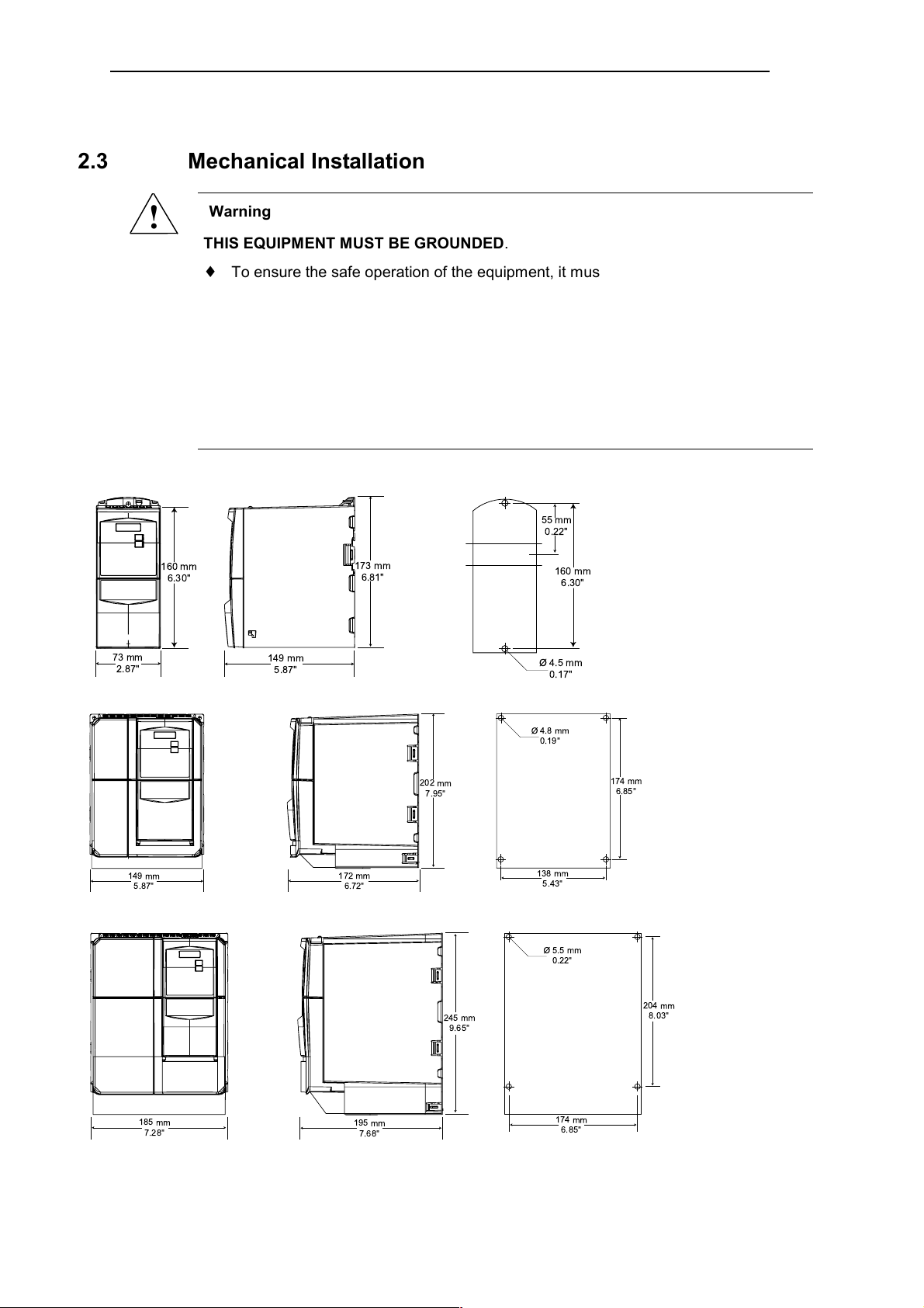
2.3 Mechanical Installation
!
4
Frame Size A:
160 mm
6.30"
73 mm
2.87"
Frame Size B:
Warning
THIS EQUIPMENT MUST BE GROUNDED.
♦ To ensure the safe operation of the equipment, it must be installed and
commissioned by qualified personnel in full compliance with the warnings laid down
in these operating instructions.
♦ Take particular note of the general and regional installation and safety regulations
regarding work on dangerous voltage installations (e.g. EN 50178), as well as the
relevant regulations regarding the correct use of tools and personal protective gear.
♦ The mains input, DC and motor terminals, can carry dangerous voltages even if the
inverter is inoperative; wait 5 minutes to allow the unit to discharge after switching
off before carrying out any installation work.
Fixing with
2 bolts M4
2 nuts M4
2 washers M4
Tightening torque (unit
to cabinet) with
washers fitted: 2.5 Nm
Connecting to DIN rail
149 mm
5.87"
173 mm
6.81"
55 mm
0.22"
160 mm
6.30"
Ø 4.5 mm
0.17"
149 mm
5.87"
Frame Size C:
185 mm
7.28"
Figure 2-1 Drill pattern for MICROMASTER 420
172 mm
6.72"
195 mm
7.68"
202 mm
7.95"
245 mm
9.65"
Ø 4.8 mm
0.19"
138 mm
5.43"
Ø 5.5 mm
0.22"
174 mm
6.85"
174 mm
6.85"
Fixing with
4 bolts M4
4 nuts M4
4 washers M4
Tightening torque (unit
to cabinet) with
washers fitted: 2.5 Nm
Fixing with
4 bolts M5
4 nuts M5
204 mm
8.03"
4 washers M5
Tightening
torque (unit to
cabinet) with
washers
fitted: 3 Nm
20 MICROMASTER 420 Operating Instructions
6SE6400-5AA00-0BP0

2. INSTALLATION International English
2.4 Electrical Installation
!
Warning
THIS EQUIPMENT MUST BE GROUNDED.
♦ To ensure the safe operation of the equipment, it must be installed and
commissioned by qualified personnel in full compliance with the warnings laid down
in these operating instructions.
♦ Take particular note of the general and regional installation and safety regulations
regarding work on dangerous voltage installations (e.g. EN 50178), as well as the
relevant regulations regarding the correct use of tools and personal protective gear.
♦ The mains input, DC and motor terminals, can carry dangerous voltages even if the
inverter is inoperative; wait 5 minutes to allow the unit to discharge after switching
off before carrying out any installation work.
♦ The inverters can be installed in a side-by-side configuration, but a distance of 100
mm (3.94 inches) must be maintained if the inverters are installed on top of each
other.
2.4.1 General
!
Warning
The inverter must always be grounded. If the inverter is not grounded correctly,
extremely dangerous conditions may arise within the inverter which could prove
potentially fatal.
Operation with ungrounded (IT) supplies
The MICROMASTER will operate from ungrounded supplies and will continue to operate
if an input phase is shorted to ground. If an output phase is shorted to ground, the
MICROMASTER will trip and indicate F0001.
On ungrounded supplies, it will be necessary to remove the ‘Y’ capacitor from the inside
of the unit and fit an output choke. The procedure for removing this capacitor is described
in Appendices E
and F.
Operation with Residual Current Device
If an RCD (also referred to as ELCB or RCCB) is fitted, the MICROMASTER inverters will
operate without nuisance tripping, provided that:
A type B RCD is used.
The trip limit of the RCD is 300mA.
The neutral of the supply is grounded.
Only one inverter is supplied from each RCD.
The output cables are less than 50m (screened) or 100m (unscreened).
MICROMASTER 420 Operating Instructions 21
6SE6400-5AA00-0BP0

International English 2. INSTALLATION
Operation with long cables
!
Caution
The control, power supply and motor leads must be laid separately. Do not feed them
through the same cable conduit/trunking. Never use high voltage insulation test
equipment on cables connected to the inverter.
All inverters will operate at full specification with cable lengths up to 50 m screened or
100 m unscreened.
2.4.2 Power and motor connections
!
!
Warning
♦ Isolate the mains electrical supply before making or changing connections to the
unit.
♦ Ensure that the motor is configured for the correct supply voltage: single / three-
phase 230 V MICROMASTERS must not be connected to a 400 V three-phase
supply.
♦ When synchronous motors are connected or when coupling several motors in
parallel, the inverter must be operated with voltage/frequency control characteristic
(P1300 = 0, 2 or 3).
Caution
After connecting the power and motor cables to the proper terminals, make sure that the
covers have been replaced properly before supplying power to the unit!
Note
♦ Ensure that the appropriate circuit-breakers/fuses with the specified current rating
are connected between the power supply and inverter (see table on page 102).
♦ Use Class 1 60/75
see table on page 101.
♦ To tighten up the power terminal screws use a 4 - 5 mm cross-tip screwdriver.
o
C copper wire only (for UL compliance). For tightening torque
Access to the power and motor terminals
The procedure for accessing the power and motor terminals on the MICROMASTER 420
Inverter is illustrated in Appendices B and C. Please also refer to the photographs
showing the Power Terminal connections and the Control Terminal connections on the
inside of the back cover of this manual.
When the covers have been removed to reveal the terminals, connect the power and
motor connections as shown on the next page.
22 MICROMASTER 420 Operating Instructions
6SE6400-5AA00-0BP0
2. INSTALLATION International English
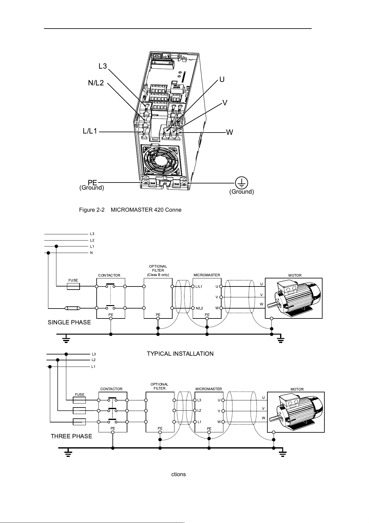
L3
N/L2
L/L1
PE
(Ground)
Figure 2-2 MICROMASTER 420 Connection Terminals
L3
L2
L1
N
U
V
W
(Ground)
FUSE
SINGLE PHASE
FUSE
THREE PHASE
CONTACTOR
L3
L2
L1
CONTACTOR
OPTIONAL
FILTER
(Class B only)
PEPE
MICROMASTER
L/L1
N/L2
PE
TYPICAL INSTALLATION
OPTIONAL
FILTER
PEPE
MICROMASTER
L3
L2
L1
PE
MOTOR
U
V
W
U
V
W
U
V
W
MOTOR
U
V
W
Figure 2-3 Motor and Power Connections
MICROMASTER 420 Operating Instructions 23
6SE6400-5AA00-0BP0

International English 2. INSTALLATION
2.4.3 Avoiding Electro-Magnetic Interference (EMI)
The inverters are designed to operate in an industrial environment where a high level of
EMI can be expected. Usually, good installation practices will ensure safe and troublefree operation. If you encounter problems, follow the guidelines stated below.
Action to Take
♦ Ensure that all equipment in the cubicle is well grounded using short, thick grounding
cable connected to a common star point or busbar
♦ Make sure that any control equipment (such as a PLC) connected to the inverter is
connected to the same ground or star point as the inverter via a short thick link.
♦ Connect the return ground from the motors controlled by the inverters directly to the
ground connection (PE) on the associated inverter
♦ Flat conductors are preferred as they have lower impedance at higher frequencies
♦ Terminate the ends of the cable neatly, ensuring that unscreened wires are as short
as possible
♦ Separate the control cables from the power cables as much as possible, using
separate trunking, if necessary at 90º to each other.
♦ Whenever possible, use screened leads for the connections to the control circuitry
♦ Ensure that the contactors in the cubicle are suppressed, either with R-C suppressors
for AC contactors or 'flywheel' diodes for DC contactors fitted to the coils. Varistor
suppressors are also effective. This is important when the contactors are controlled
from the inverter relay
♦ Use screened or armored cables for the motor connections and ground the screen at
both ends using the cable clamps
!
Warning
Safety regulations must not be compromised when installing inverters!
24 MICROMASTER 420 Operating Instructions
6SE6400-5AA00-0BP0
2. INSTALLATION International English
1
5
1
1
2
4
3
2
L1
6
L2
L3
3
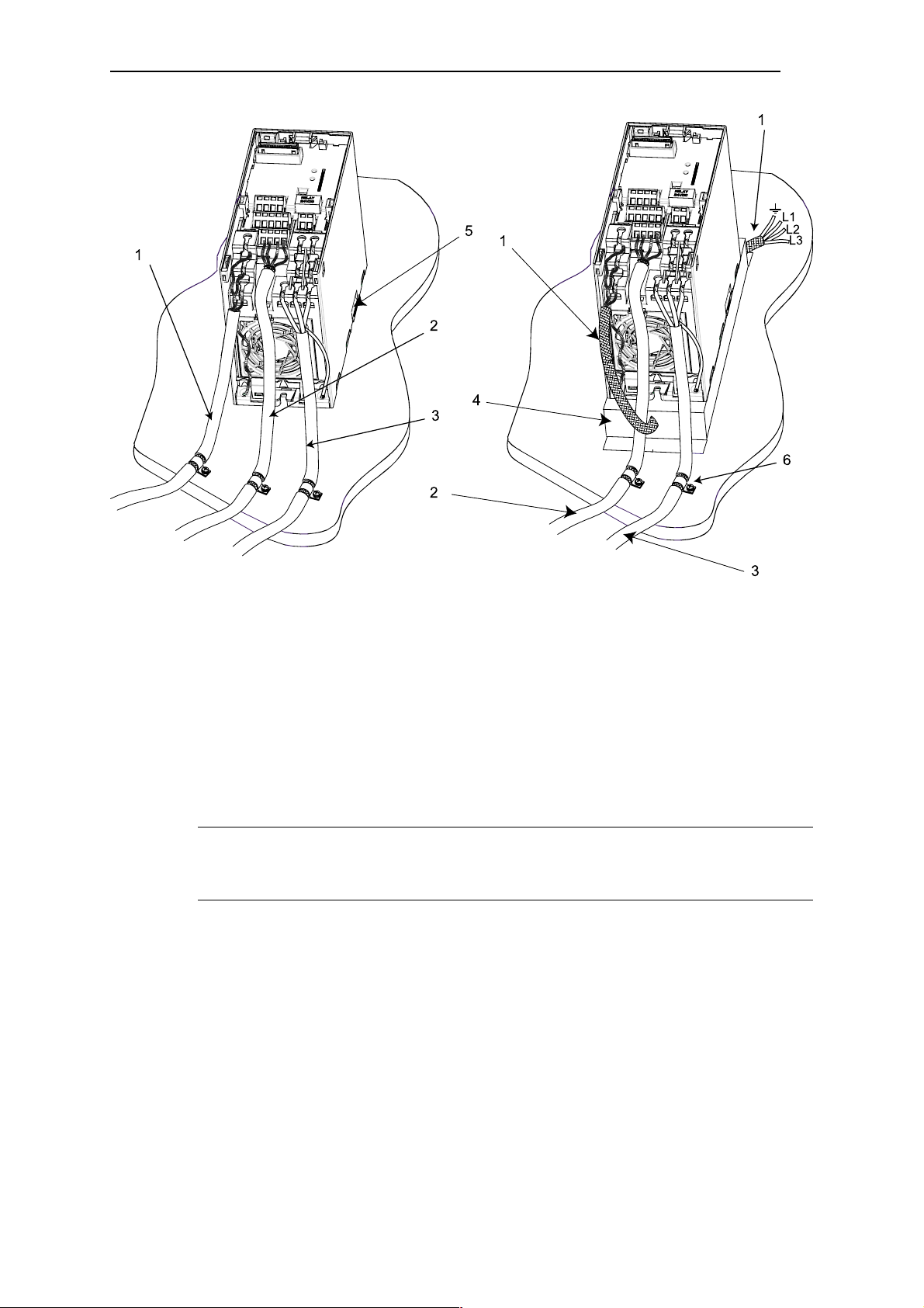
Figure 2-4 Wiring Guidelines to Minimize the Effects of EMI
Key Meaning in diagrams above
1 Mains power input
2 Control cable
3 Motor cable
4 Footprint filter
5 Metal back plate
6 Use suitable clips to fix motor and control cable screens securely to metal
back plate
Note
To enhance the screening of the motor and control cables, the optional Gland Plate can
be used (not shown in Figure 2-4).
MICROMASTER 420 Operating Instructions 25
6SE6400-5AA00-0BP0

International English 2. INSTALLATION
26 MICROMASTER 420 Operating Instructions
6SE6400-5AA00-0BP0

3. COMMISSIONING International English
3 Commissioning
This Chapter contains:
♦ Description of the front panel controls
♦ A brief description of the optional front panels available and an explanation of the
operation of the Basic Operator Panel (BOP)
♦ An 8-step guide at the end of the Chapter, which provides a simple procedure for
changing parameters
3.1 Front Panels for the MICROMASTER 420 ................................................................. 29
3.2 General operation....................................................................................................... 34
MICROMASTER 420 Operating Instructions 27
6SE6400-5AA00-0BP0

International English 3. COMMISSIONING
!
Warning
♦ MICROMASTERS operate at high voltages.
♦ When operating electrical devices, it is impossible to avoid applying hazardous
voltages to certain parts of the equipment.
♦ Emergency Stop facilities according to EN 60204 IEC 204 (VDE 0113) must remain
operative in all operating modes of the control equipment. Any disengagement of
the Emergency Stop facility must not lead to uncontrolled or undefined restart.
♦ Wherever faults occurring in the control equipment can lead to substantial material
damage or even grievous bodily injury (i.e. potentially dangerous faults), additional
external precautions must be taken or facilities provided to ensure or enforce safe
operation, even when a fault occurs (e.g. independent limit switches, mechanical
interlocks, etc.).
♦ Certain parameter settings may cause the inverter to restart automatically after an
input power failure.
♦ This equipment is capable of providing internal motor overload protection in
accordance with UL508C section 42. Refer to P0610 (level 3) and P0335, I
by default. Motor overload protection can also be provided using an external PTC
via a digital input.
♦ This equipment is suitable for use in a circuit capable of delivering not more than
10,000 symmetrical amperes (rms), for a maximum voltage of 230/460V when
protected by a time delay fuse (see Table on page 102).
♦ This equipment must not be used as an ‘emergency stop mechanism’ (see EN
60204, 9.2.5.4)
2
T is ON
!
Caution
Only qualified personnel may enter settings in the control panels. Particular attention
must be paid to safety precautions and warnings at all times.
The MICROMASTER 420 is supplied with a Status Display Panel (SDP) and default
parameter settings that cover the following requirements:
♦ The motor rating data, voltage, current and frequency are all compatible with the
inverter data. (A standard Siemens motor is recommended).
♦ Linear V/f motor speed, controlled by an analogue potentiometer.
-1
♦ Maximum speed 3000 min
potentiometer via the inverter’s analogue inputs
♦ Ramp-up time / Ramp-down time = 10 s
If more complex application settings are required, please refer to the parameter listing in
these Operating Instructions.
For changing parameters you will need one of the optional modules "Basic Operator
Panel" (BOP) or the "Advanced Operator Panel" (AOP) described below.
Furthermore the parameters can be changed by communication options (refer to the
Reference Manual).
For instruction on how to exchange/replace the Operator Panels see Appendix A
Note
with 50 Hz (3600 min-1 with 60 Hz), controllable using a
♦ The same BOP/AOP can be used for each MICROMASTER 420. After changing
the parameters replace the BOP/AOP by the SDP.
♦ The terminal layout for connecting power and control cables is shown in the
photograph on the inside of the back cover of this manual.
28 MICROMASTER 420 Operating Instructions
6SE6400-5AA00-0BP0
3. COMMISSIONING International English
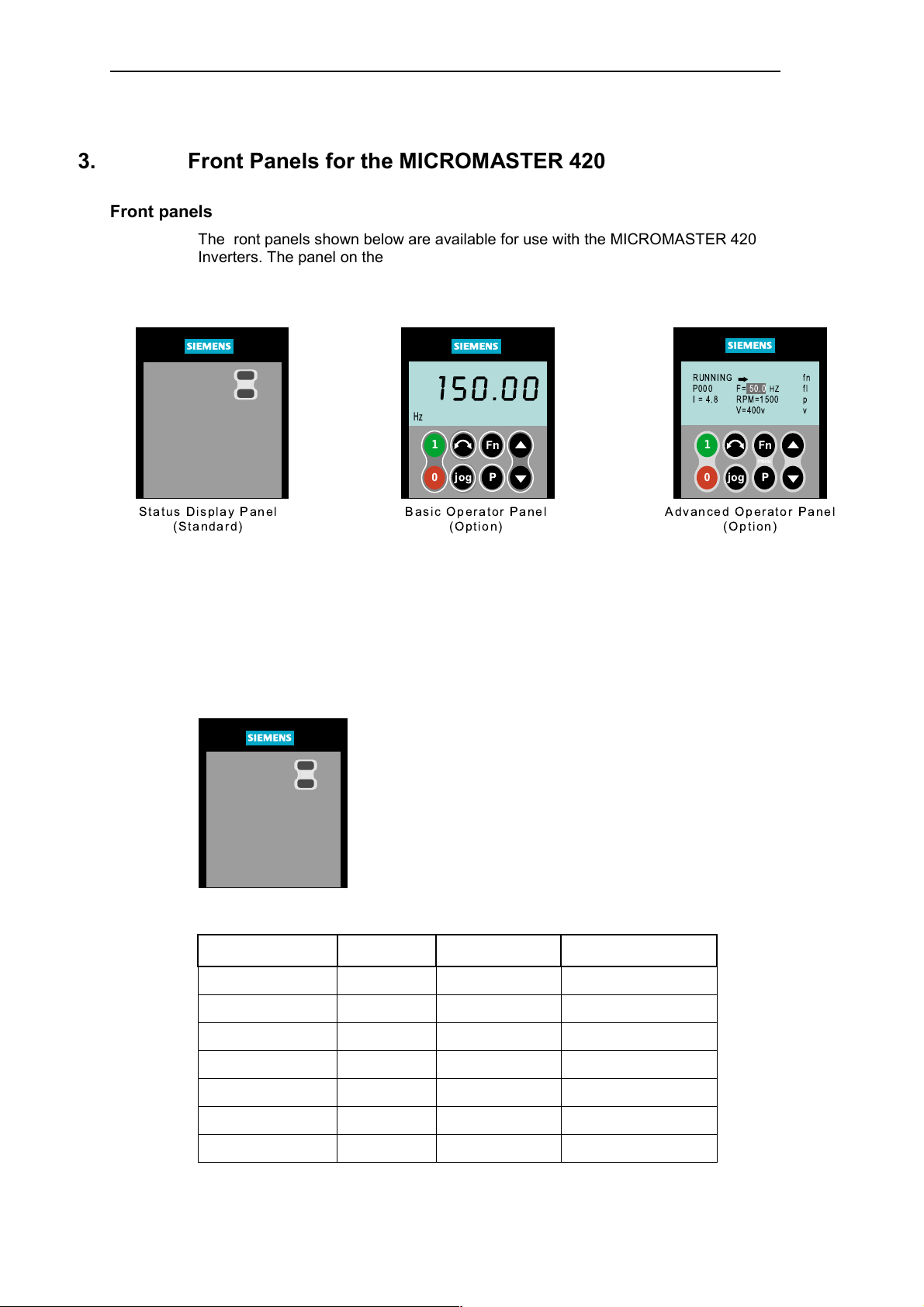
3.1 Front Panels for the MICROMASTER 420
Front panels
The front panels shown below are available for use with the MICROMASTER 420
Inverters. The panel on the left is supplied with the inverter as standard and is referred to
as the Status Display Panel (SDP). The Basic Operator Panel (BOP) and Advanced
Operator Panel (AOP) are available as options.
150.00
Hz
Hz
1
0
Status Display Panel
(Standard)
Basic Operator Panel
Figure 3-1 Panels available for the MICROMASTER 420 Inverter
Changing the front panel
The procedure for removing the SDP and fitting the BOP or AOP, which are available as
options, is described in Appendix A.
3.1.1 Commissioning with the Status Display Panel (SDP)
The SDP is supplied with your MICROMASTER 420 Inverter as
standard. This panel has two LEDs on the front, which indicate
the operational status of the inverter.
With the SDP the inverter can be used with its default settings,
for many applications. The default settings are shown in Table
3.1
Fn
P
jog
(Option)
RUNNING
P000
F= 50.0
I = 4.8
RPM=1500
V=400v
1
0
jog
Advanced Operator Panel
(Option)
Fn
menu
P
HZ
fn
fl
p
v
The terminal layout is shown in the photograph of the Control
Terminal Connections on the inside of the back cover of this
manual.
Table 3-1 Default settings for operation using the Status Display Panel
Terminals Parameter Default Operating
Digital Input 1 5 P0701 = ‘1’ ON right
Digital Input 2 6 P0702 = ‘12’ Reverse
Digital Input 3 7 P0703 = ‘9’ Fault Reset
Output Relay 10/11 P0731 = ’52.3’ Fault Identification
Analogue Output 12/13 P0771 = 21 Output Frequency
Analogue input 3/4 P0700 = 0 Frequency Setpoint
1/2 Analog Input supply
MICROMASTER 420 Operating Instructions 29
6SE6400-5AA00-0BP0
International English 3. COMMISSIONING
Warnings and faults states on the Status Display Panel
The two LEDs on the Status Display Panel indicate the operating status of your inverter.
These LEDs also indicate various warnings or fault states. In section 6.1 the inverter
states, indicated by the two LEDs are explained.
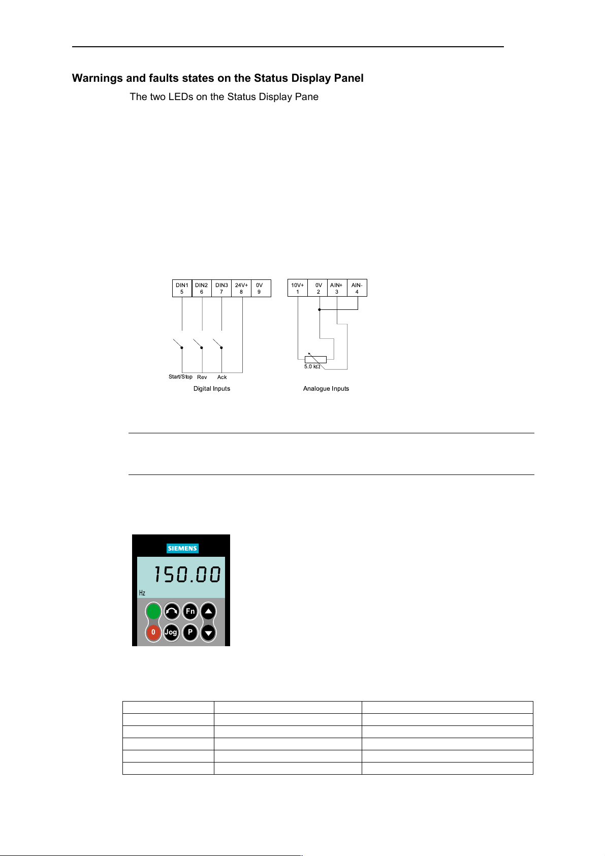
3.1.2 Basic operation with SDP
With the SDP fitted, the following is possible:
♦ Start and stopping the motor
♦ Reversing the motor
♦ Fault Reset
Controlling the speed of the motor
Connect the terminals as shown in the figure below.
DIN15DIN26DIN3724V+80V
9
10V+10V2AIN+3AIN-
4
5.0 k
Start/Stop
Figure 3-2 Basic operation with SDP
Ack
Rev
Digital Inputs Analogue Inputs
W
Note
The terminal layout for connecting power and control cables is shown in the photographs
on the inside of the back cover of this manual.
3.1.3 Commissioning with the Basic Operator Panel (BOP)
The Basic Operator Panel (BOP), which is available as an
option, provides access to the inverter parameters and enables
you to customize the settings of your MICROMASTER 420. The
BOP can be used to configure several MICROMASTER 420
150.00
Hz
Inverters. There is no need to purchase a separate BOP for each
inverter.
1
0
Jog
Fn
It should be noted that the BOP motor control functions are
disabled by default. To control the motor via the BOP, parameter
P
P0700 should be set to 1.
Table 3-2 shows the factory default settings for operation via the
Basic Operator Panel.
Table 3-2 Default settings for operation using the BOP
Parameter Meaning Default Europe (North America)
P0100 Operating Mode Europe/US 50 Hz, kW (60Hz, hp)
P0307 Power (rated motor) kW (Hp)
P0310 Motor frequency rating 50 Hz (60 Hz)
P0311 Motor speed rating 1395 (1680) rpm [depending on variant]
P1082 Maximum Motor Frequency 50 Hz (60 Hz)
30 MICROMASTER 420 Operating Instructions
6SE6400-5AA00-0BP0
 Loading...