


1015N-2MFM-1A
Table of contents
 Loading...
1015N-2MFM-1A
FIELD MANUAL
1015N-2M DIAL-UP MODEM
OPTION CARD
FOR SYSTEM 1010N
FLOWMETERS
FOR TECHNICAL ASSIST ANCE
Call: (800) 275-8480
(631) 231-3600
Fax: (631) 231-3334
E-mail: TSG .ultrasonicflow@siemens.com
FOR GENERAL INFORMA TION
Website: www.controlotron.com
E-mail: info.ultrasonicflow@siemens.com
Or: sales.ultrasonicflow@siemens.com
Copyright©2006 Siemens Energy & Automation, Inc. All Rights Reserved Made in the USA

IMPORTANT NOTICE
Controlotron is now part of:
Siemens Energy & Automation, Inc.
Process Instrumentation Business Unit (PI BU)
CoC Ultrasonic Flow
1015N-2M DIAL-UP MODEM
OPTION CARD
FOR SYSTEM 1010N
FLOWMETERS
This equipment contains components that are
susceptible to electrostatic discharge (ESD).
Please observe ESD control measures during
the handling and connection process.
Field Manual 1015N-2MFM-1A
June 2006
For use with Operating System
Software Version 2.00.15 or later
Prepared By Date
Reviewed By Date
FOR TECHNICAL ASSISTANCE: FOR GENERAL INFORMATION:
Call: (800) 275-8480 Website: www .controlotron.com
(631) 231-3600 E-mail: info.ultrasonicflow@siemens.com
Fax: (631) 231-3334 Or: sales.ultrasonicflow@siemens.com
E-mail: TSG .ultrasonicflow@siemens.com
Copyright©2006 Siemens Energy & Automation, Inc. All Rights Reserved Made in the USA
Printed June 2006

Manual Changes
NOTE: For the latest updates and revisions to this field manual go to
www.controlotron.com/downloads.htm and check the Product Manual
listing.

Table Of Contents
1. Introduction ......................................................................................................1
2. 1015N-2M Modem Card Setup ......................................................................1
2.1 Option 1 Mounting Kit 1015N-2M-MK1 ......................................................1
2.2 Option 2 Mounting Kit 1015N-2M-MK2 ......................................................1
2.3 Option 3 Mounting Kit 1015N-2M-MK3 ......................................................1
3. Technical Specifications................................................................................. 2
4. 1010N Flowmeter System Requirements ..................................................2
5. Preliminary Installation Notes and Cautions ...........................................2
5.1 1015N-2M Modem Card Installation ........................................................... 2
5.1.1 Option 1 Installation Procedure (Mounting Kit 1015N-2M-MK1) .......3
5.1.2 Option 2 Installation Procedure (Mounting Kit 1015N-2M-MK2) .......5
5.1.3 Option 3 Installation Procedure (Mounting Kit 1015N-2M-MK3) .......6
5.2 Setting 1010N Flowmeter RS-232 Parameters ......................................... 8
5.3 Telephone Line Connections ........................................................................ 8
6. Communications Configuration ................................................................... 9
7. Windows HyperTerminalTM Setup ............................................................... 9
1015N-2MFM-1A
TABLE OF CONTENTS
Page
Figure 1. 1015N-2M Modem Card and Attaching Hardware ................2
Module Loading Option 1 .......................................................................... 3
Module Loading Option 2 .......................................................................... 3
Module Loading Option 3 .......................................................................... 3
Figure 2. 1010N Flowmeter Access Cover Removal ............................... 3
Figure 3. Option 1 Installation (side view) .............................................4
Figure 4. Option 2 Installation (side view) .............................................6
Figure 5. Option 2 Installation (side view) .............................................7
1015N-2M Reconfiguration Procedure..................................................... 9
APPENDICES
Appendix A “AT” Command Set and “S” Registers .............................................. A-1
“AT” Commands .................................................................................. A-2
“S” Registers ........................................................................................ A-4
“AT” Commands and “S” Registers Exclusive to the PE2400 ......... A-5
Dial Modifiers ................................................................................ A-5
Ampersand (AT&) Commands ..................................................... A-6
Percent (AT%) Commands ...........................................................A-6
“S” Registers .................................................................................. A-7
Appendix B Engineering Drawings ..........................................................................B-1
i

1015N-2MFM-1A
1015N-2MFM-1 MODEM CARD
INSTALLATION INSTRUCTIONS
1. INTRODUCTION
The 1015N-2M Modem Card is one of three option cards used for remote communications
within the Controlotron 1010N family of flowmeters. External communication is achieved
through an on board dial-up miniature modem with asynchronous line speeds of 2400 bps,
1200 bps, or 300 bps. Implementation of Windows HyperTerminalTM or any other
communication software allows for the direct control of the modem’s Hayes compatible
command set.
2. 1015N-2M MODEM CARD KITS
2.1 OPTION 1 MOUNTING KIT 1015N-2M-MK1
Description Part Number Qty
Cover, Communication Module 1010-436-1 1
Screw, Captive 6-32 x 1/2 4006M07F09 1
Label, Controlotron ID 1010-257 1
Standoff, Threaded, Cover Mount 1010-433-1 1
Standoff, Threaded, PCB Support 1010-434-1 4
Cover, Analog Input Module 1010-379 1
Installation Drawing 1015N-2M-MK-7 1
Installation, Wiring Drawing 1015N-2M-7 1
Insulator, Syscom shield, 1010N 1010-263 1
2.2 OPTION 2 MOUNTING KIT 1015N-2M-MK2
Description Part Number Qty
Cover, I/O Board 1010-446-1 1
Screw, Captive 6-32 x 1/2 4006M07F09 1
Label, Controlotron ID 1010-257 1
Standoff, Cover Mount 1010-447-1 1
Standoff, Threaded, PCB Support 1010-434-1 4
Installation Drawing 1015N-2M-MK-7 1
Installation, Wiring Drawing 1015N-2M-7 1
2.3 OPTION 3 MOUNTING KIT 1015N-2M-MK3
Description Part Number Qty
Cover, I/O Board 1010-446-2 1
Screw, Captive 6-32 x 1/2 4006M07F09 1
Label, Controlotron ID 1010-257 1
Standoff, Cover Mount 1010-447-1 1
Standoff, Threaded, PCB Support 1010-434-1 4
Installation Drawing 1015N-2M-MK-7 1
Installation Drawing 1015N 1
Installation, Wiring Drawing 1015N-2M-7 1
1

TB1 Network Connection
(2-Wire Hook Up)
Con 2 Network Connection
(RJ11 Connector)
1015N-2M
Modem Card
Module ID Label
Top View Side View
Figure 1. 1015N-2M Modem Card and Attaching Hardware
3. TECHNICAL SPECIFICATIONS
1015N-2MFM-1A
Captive
Screws (4)
Interface: RS-232
Supply Voltage: 5 volts DC
Supply Current: 48 mA
Modem Line Speeds: 2400, 1200 and 300 bps Asynchronous
DTE Rates: 2400, 1200, 300 bps
Modulation: V.22bis, V.22, Bell 212A, Bell 103
Phone Line: Dial Up or 2 Wire Leased Line
Extended Hayes Command Set Compatibility
Error Correction / Error Detection: None
Operating Environment: -40 to 85 degrees C / 0 to 95% Humidity (non-condensing)
4. 1010N FLOWMETER SYSTEM REQUIREMENTS
The System 1010N Flowmeter operating system must be revision level 2.0 or later for the
1015N-2M Modem Card to function properly. In addition, the 1015N-2M Modem Card
requires 1010N system hardware of the following levels in order to work. Refer to the
appropriate 1010N user manual installation/outline drawings for circuit board locations.
a. 1010N-1-5 SysCom Version 3, Revision. D2 or Higher
b. 1010N-2K3 I/O Board A2
c. 1010N-8M-5 I/O Board A3
d. 1010N-7K2 Analog I/O A2
5. PRELIMINARY INSTALLATION NOTES AND CAUTIONS
CAUTION: It is highly recommended that installation be done in a static free
environment or damage to the 1015N-2M Modem Card may result.
NOTE: The 1015N-2M Modem will not function if the 1010 flowmeter RS-232 port is
connected to the serial port of your PC.
NOTE: The 1015N-2M Modem will only transmit and receive data when used with
direct phone line connections (see paragraph 5.3 below for communication
connection options).
2
1015N-2MFM-1A
5.1 1015N-2M MODEM CARD INSTALLATION
WARNING: Set flowmeter and instrumentation power to OFF when inserting or
removing the 1015N-2M Modem Card.
Before proceeding with the following installation procedures, identify the Module Loading
option and installation drawing for your Modem Card (see Appendix A). The options are as
follows:
a. Module Loading Option 1
1010N-5 with 1010N-2 in 1010N/DN Type System. Use Mounting Kit 1015N-2M-MK1. Refer
to Installation Drawing 1015N-2M-MK-7 (sheet 1 of 3). Proceed to paragraph 5.1.1.
b. Module Loading Option 2
1010N-2 only in 1010N/DN Type System. Use Mounting Kit 1015N-2M-MK2. Refer to
Installation Drawing 1015N-2M-MK-7 (sheet 2 of 3). Proceed to paragraph 5.1.2.
c. Module Loading Option 3
1010N-8M with 1010N-2M in 1010MN Type System. Use Mounting Kit 1015N-2M-MK3.
Refer to Installation Drawing 1015N-2M-MK-7 (sheet 3 of 3). Proceed to paragraph 5.1.3.
5.1.1 OPTION 1 INSTALLATION PROCEDURE (Mounting Kit 1015N-2M-MK1)
1010N-5 Module with 1010N-2 Module in 1010N/DN Type System
(Refer to Installation Drawing 1015N-2M-MK-7 sheet 1 of 3)
DISASSEMBLY (see Figure 2 and Figure 3)
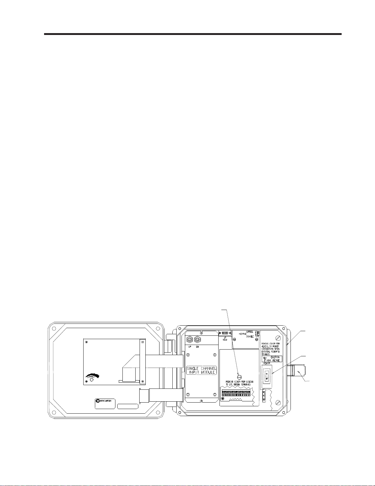
1. Referring to Figure 1, open the 1010 NEMA flowmeter top cover by releasing the cover
latch.
2. Place the power switch to the OFF position.
3. Loosen the captive thumbscrew securing the Access Cover and remove Access Cover.
Access Cover
Screw
1010N
Power Switich
Cover Latch
Figure 2. 1010N Flowmeter Access Cover Removal
3
1015N-2MFM-1A
CAUTION: Do not connect a serial data cable to J1 on the 1015N-2M Modem Card or
damage to the Modem Card and flowmeter may result.
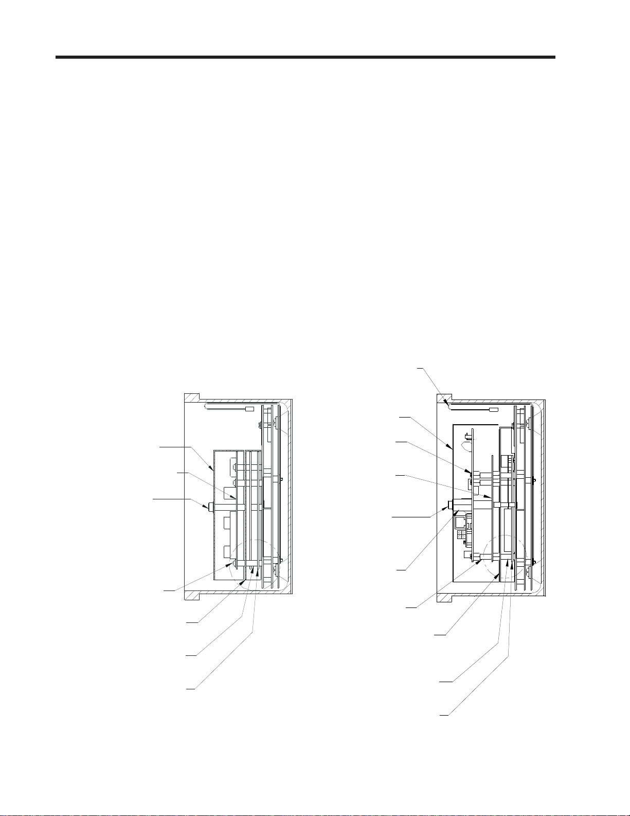
4. Loosen the four captive screws (1) at the corners of the 1010N-2 module (7) and carefully
lift out the module disengaging it from the connector on the 1010N-5 module (2).
5. Lift off the shield (3) covering the 1010N-5 module (2).
6. Leave the 1010N-5 module in place. Check to assure that the four corner standoffs (4) are
securely threaded in place.
ASSEMBLY (see Figure 3)
7. Install shield (5) supplied with the 1015N-2M-MK1 mounting kit and cover the 1010N-5
module. Note: This shield replaces the shield removed in Step 5 above.
8. Remove the four captive screws (1) from the 1010N-2 module loosened in Step 4 above.
Install standoffs (6) from mounting kit in the vacant positions.
9. Install the 1010N-2 module (7) carefully engaging connector P1 to the 1010N-5 module (2).
Secure by threading the four standoffs (6) installed in Step 5 above with their mates on
the 1010N-5 module.
10. Check for properly alignment of P1.
START VIEW
(11) 1010N-2 I/O
Module Cover
(9) 1010N-2 I/O Module
(12) Captive Screw
(1) 1010N-2 Captive Screws
(3) 1010N-5 Analog Module Shield
(4) Threaded Standoffs
Serial Data Cable - Not
used with 1015N-2M
Modem Card.
FINISH VIEW
(11) 1010N-2 I/O
Module Cover
(9) 1015N-2M
Modem Card
(7) 1010N-2
I/O Module
(12) Captive Screw
(10) Cover Mount
Standooff
(6) Threaded Standoff
(5) 1010N-5 Analog
Module Shield
(2) 1010N-5 Analog Module Assy
(4) Threaded Standoffs
(2) 1010N-5 Analog Module Assy
Figure 3. Option 1 Installation (side view)
4
Loading...