


 Loading...
LCD-TV
Chassis : N89B/N89A
Model : LA19C350D1
LA22C350D1
LA26C350D1
LA32C350D1
SERVICE Manual 
TFT-LCD TV |
|
Contents |
|
|
|
1. Precautions
2. Product specifications
3. Disassembly and Reassembly
4. Troubleshooting
5. Exploded View & Part List
6. Wiring Diagram
LA19C350D1/LA22C350D1
LA26C350D1/LA32C350D1
Refer to the service manual in the GSPN (see the rear cover) for the more information.
Contents
1. Precautions............................................................................................................... |
1-1 |
|
1-1. |
Safety Precautions.......................................................................................................... |
1-1 |
1-2. |
Servicing Precautions...................................................................................................... |
1-2 |
1-3. |
Electrostatically Sensitive Devices (ESD) Precautions................................................... |
1-2 |
1-4. |
Installation Precautions................................................................................................... |
1-3 |
2. Product specifications............................................................................................. |
2-1 |
|
2-1. |
Feature & Specifications................................................................................................. |
2-1 |
2-2. |
Specification Comparison to Old Models...................................................................... |
2-12 |
2-3. |
Wall Mount.................................................................................................................... |
2-13 |
3. Disassembly and Reassembly................................................................................ |
3-1 |
3-1. Disassembly and Reassembly (LA19", 22"C350)........................................................... |
3-1 |
3-2. Disassembly and Reassembly (LA26", 32"C350)........................................................... |
3-4 |
4. Troubleshooting....................................................................................................... |
4-1 |
4-1. Troubleshooting............................................................................................................... |
4-1 |
4-2. Alignments and Adjustments......................................................................................... |
4-13 |
4-3. Factory Mode Adjustments............................................................................................ |
4-14 |
4-4. White Balance - Calibration........................................................................................... |
4-25 |
4-5. How To Upgrade............................................................................................................ |
4-27 |
4-6. Servicing Information..................................................................................................... |
4-27 |
5. Exploded View & Part List....................................................................................... |
5-1 |
5-1. LA19C350D1 Exploded View.......................................................................................... |
5-1 |
5-2. LA19C350D1 Parts List................................................................................................... |
5-3 |
5-3. LA22C350D1 Exploded View.......................................................................................... |
5-5 |
5-4. LA22C350D1 Parts List................................................................................................... |
5-7 |
5-5. LA26C350D1 Exploded View.......................................................................................... |
5-9 |
5-6. LA26C350D1 Parts List................................................................................................. |
5-11 |
5-7. LA32C350D1 Exploded View........................................................................................ |
5-16 |
5-8. LA32C350D1 Parts List................................................................................................. |
5-18 |
6. Wiring Diagram......................................................................................................... |
6-1 |
6-1. Wiring Diagram................................................................................................................ |
6-1 |
6-2. Connector........................................................................................................................ |
6-2 |
6-3. Connector Functions....................................................................................................... |
6-3 |
6-4. Cables............................................................................................................................. |
6-3 |

GSPN (Global Service Partner Network)
Area |
Web Site |
|
|
North America |
http://service.samsungportal.com |
|
|
Latin America |
http://latin.samsungportal.com |
|
|
CIS |
http://cis.samsungportal.com |
|
|
Europe |
http://europe.samsungportal.com |
|
|
China |
http://china.samsungportal.com |
|
|
Asia |
http://asia.samsungportal.com |
|
|
Mideast & Africa |
http://mea.samsungportal.com |
|
|
This Service Manual is a property of Samsung Electronics Co.,Ltd.
Any unauthorized use of Manual can be punished under applicable International and/or domestic law.
© 2010 Samsung Electronics Co.,Ltd. All rights reserved.
Printed in Korea
P/N: BN82-00739A-00

2. Product specifications
2. Product specifications
2-1. Feature & Specifications
Model |
LA19C350D1 |
|
|
Feature
RF, 1-HDMI, 1-Component, 1-AV, 1-USB2.0, D-SUB, MEDIA PLAY, Headphone OutBrightness : 350cd/m2
Contrast Ratio : 3000:1Response time : 8.5ms
|
|
Specifications |
|
|
|
|
|
Item |
|
Description |
|
|
|
|
|
LCD Panel |
19 inch HD 60Hz |
||
|
|
|
|
Scanning Frequency |
Horizontal : 60 kHz ~ 73 kHz (Automatic) |
||
|
Vertical : 40 Hz ~ 75 Hz (Automatic) |
||
|
|
|
|
Display Colors |
16.7 million colors |
||
|
|
|
|
Maximum resolution |
Horizontal : 1366 Pixels |
||
|
Vertical : 768 Pixels |
||
|
|
|
|
Input Signal |
Analog 0.7 Vp-p ± 5% positive at 75Ω , internally terminated |
||
|
|
|
|
Input Sync Signal |
H/V Separate, TTL, P. or N. |
||
|
|
|
|
Maximum Pixel Clock rate |
86MHz |
|
|
|
|
|
|
Active Display |
409.8 (H) x 230.4 (V) mm |
||
Horizontal/Vertical |
|||
|
|
|
|
AC power voltage & Frequency |
AC 110V ~ 240V, 50/60Hz |
||
|
|
|
|
Power Consumption |
< 35W (< 1W, Stand by) |
||
|
|
|
|
Dimensions |
461.2 x 161.0 x 364.0 mm_with stand |
||
Set (W x D x H) |
|||
461.2 x 59.5(64.4) x 322.2 mm_without stand |
|||
|
|||
|
|
|
|
Weight (Set) |
3.9kg_with stand |
||
|
4.1kg_without stand |
||
|
|
|
|
TV System |
Tuning |
Frequency Synthesize (Refer to detailed Frequency Table) |
|
|
|
|
|
|
System |
PAL, SECAM, NT4.43,NT3.58 |
|
|
|
|
|
|
Sound |
BG, DK, M, I |
|
|
|
|
|
Environmental Considerations |
Operating Temperature: 32˚F ~ 122˚F (0˚C ~ 50˚C) |
||
|
Operating Humidity: 20% ~ 90% |
||
|
Storage Temperature: -4˚F ~ 140˚F (-20˚C ~ 60˚C) |
||
|
Storage Humidity: 5% ~ 90% |
||
|
|
||
Audio spec. |
- MAX Internal Audio Output Power : Each 5W(Left/Right) |
||
|
- Equalizer : 5band |
||
|
- Output Frequency : RF : 20 Hz ~ 15.4 kHz |
||
|
|
AV/Componet/HDMI : 20 Hz ~ 20 kHz |
|
|
|
|
|
2-1

2. Product specifications
Model |
LA22C350D1 |
|
|
Feature
RF, 1-HDMI, 1-Component, 1-AV, 1-USB2.0, D-SUB, MEDIA PLAY, Headphone OutBrightness : 350cd/m2
Contrast Ratio : 3000:1Response time : 8.5ms
|
|
Specifications |
|
|
|
Item |
|
Description |
|
|
|
LCD Panel |
22 inch HD 60Hz |
|
|
|
|
Scanning Frequency |
Horizontal : 60 kHz ~ 73 kHz (Automatic) |
|
|
Vertical : 40 Hz ~ 75 Hz (Automatic) |
|
|
|
|
Display Colors |
16.7 million colors |
|
|
|
|
Maximum resolution |
Horizontal : 1366 Pixels |
|
|
Vertical : 768 Pixels |
|
|
|
|
Input Signal |
Analog 0.7 Vp-p ± 5% positive at 75Ω , internally terminated |
|
|
|
|
Input Sync Signal |
H/V Separate, TTL, P. or N. |
|
|
|
|
Maximum Pixel Clock rate |
86MHz |
|
|
|
|
Active Display |
|
|
Horizontal/Vertical |
477.417(H) X 268.416(V) mm |
|
|
|
|
AC power voltage & Frequency |
AC 110V ~ 240V, 50/60Hz |
|
|
|
|
Power Consumption |
< 55W (< 1W, Stand by) |
|
|
|
|
Dimensions |
|
|
Set (W x D x H) |
535.3 x 171.8 x 420.9mm_with stand |
|
|
535.3 x 82.2(85.5) x 365.8mm_without stand |
|
|
|
|
Weight (Set) |
3.9kg_with stand |
|
|
4.2kg_without stand |
|
|
|
|
TV System |
Tuning |
Frequency Synthesize (Refer to detailed Frequency Table) |
|
|
|
|
System |
PAL, SECAM, NT4.43,NT3.58 |
|
|
|
|
Sound |
BG, DK, M, I |
|
|
|
Environmental Considerations |
Operating Temperature: 32˚F ~ 122˚F (0˚C ~ 50˚C) |
|
|
Operating Humidity: 20% ~ 90% |
|
|
Storage Temperature: -4˚F ~ 140˚F (-20˚C ~ 60˚C) |
|
|
Storage Humidity: 5% ~ 90% |
|
|
|
|
Audio spec. |
- MAX Internal Audio Output Power : Each 5W(Left/Right) |
|
|
- Equalizer : 5band |
|
|
- Output Frequency : RF : 20 Hz ~ 15.4 kHz |
|
|
|
AV/Componet/HDMI : 20 Hz ~ 20 kHz |
|
|
|
2-2

2. Product specifications
Model |
LA26C350D1 |
|
|
Feature
RF, 1-HDMI, 1-Component, 1-AV, 1-USB2.0, D-SUB, MEDIA PLAY, Audio OutBrightness : 350cd/m2
Contrast Ratio : 3000:1Response time : 8.5ms
|
|
Specifications |
|
|
|
Item |
|
Description |
|
|
|
LCD Panel |
26 inch HD 60Hz |
|
|
|
|
Scanning Frequency |
Horizontal : 60 kHz ~ 73 kHz (Automatic) |
|
|
Vertical : 40 Hz ~ 75 Hz (Automatic) |
|
|
|
|
Display Colors |
16.7M color |
|
|
|
|
Maximum resolution |
Horizontal : 1366 Pixels |
|
|
Vertical : 768 Pixels |
|
|
|
|
Input Signal |
Analog 0.7 Vp-p ± 5% positive at 75Ω , internally terminated |
|
|
|
|
Input Sync Signal |
H/V Separate, TTL, P. or N. |
|
|
|
|
Maximum Pixel Clock rate |
86MHz |
|
|
|
|
Active Display |
|
|
Horizontal/Vertical |
22.73 x 12.81 inchs (577.4(H) x 325.4(V) mm) |
|
|
|
|
AC power voltage & Frequency |
AC 110V ~ 220V, 60 Hz |
|
|
|
|
Power Consumption |
< 60W (< 1W, Stand by) |
|
|
|
|
Dimensions |
|
|
Set (W x D x H) |
673.3 x 222.2 x 513.4 mm_with stand |
|
|
673.3 x 84.0 x 456.0 mm_without stand |
|
|
|
|
Weight (Set) |
6.1kg_with stand |
|
|
5.6kg_without stand |
|
|
|
|
TV System |
Tuning |
Frequency Synthesize (Refer to detailed Frequency Table) |
|
|
|
|
System |
PAL, SECAM, NT4.43, NT3.58 |
|
|
|
|
Sound |
BG, DK, M, I |
|
|
|
Environmental Considerations |
Operating Temperature: 32˚F ~ 122˚F (0˚C ~ 50˚C) |
|
|
Operating Humidity: 20% ~ 90% |
|
|
Storage Temperature: -4˚F ~ 140˚F (-20˚C ~ 60˚C) |
|
|
Storage Humidity: 5% ~ 90% |
|
|
|
|
Audio Spec. |
- MAX Internal Audio Output Power : Each 5W(Left/Right) |
|
|
- Equalizer : 5band |
|
|
- Output Frequency : RF : 20 Hz ~ 15.4 kHz |
|
|
|
AV/Componet/HDMI : 20 Hz ~ 20 kHz |
|
|
|
2-3

2. Product specifications
Model |
LA32C350D1 |
|
|
Feature
RF, 1-HDMI, 1-Component, 1-AV, 1-USB2.0, D-SUB, MEDIA PLAY, Audio OutBrightness : 400cd/m2
Contrast Ratio : 3000:1Response time : 8.5ms
|
|
Specifications |
|
|
|
Item |
|
Description |
|
|
|
LCD Panel |
32 inch HD 60Hz |
|
|
|
|
Scanning Frequency |
Horizontal : 43 kHz ~ 53 kHz (Automatic) |
|
|
Vertical : 47 Hz ~ 63 Hz (Automatic) |
|
|
|
|
Display Colors |
16.7 million colors |
|
|
|
|
Maximum resolution |
Horizontal : 1366 Pixels |
|
|
Vertical : 768 Pixels |
|
|
|
|
Input Signal |
Analog 0.7 Vp-p ± 5% positive at 75Ω , internally terminated |
|
|
|
|
Input Sync Signal |
H/V Separate, TTL, P. or N. |
|
|
|
|
Maximum Pixel Clock rate |
86MHz |
|
|
|
|
Active Display |
|
|
Horizontal/Vertical |
27.54 x 15.52 inches (699.6(H) x 394.3(V) mm) |
|
|
|
|
AC power voltage & Frequency |
AC 110V ~ 240V, 50/60Hz |
|
|
|
|
Power Consumption |
< 90W (< 1W, Stand by) |
|
|
|
|
Dimensions |
|
|
Set (W x D x H) |
795.3 x 247.2 x 585.3 mm_with stand |
|
|
795.3 x 84.0 x 525.8 mm_without stand |
|
|
|
|
Weight (Set) |
7.6kg_with stand |
|
|
7.1kg_without stand |
|
|
|
|
TV System |
Tuning |
Frequency Synthesize (Refer to detailed Frequency Table) |
|
|
|
|
System |
PAL, SECAM, NT4.43,NT3.58 |
|
|
|
|
Sound |
BG, DK, M, I |
|
|
|
Environmental Considerations |
Operating Temperature: 32˚F ~ 122˚F (0˚C ~ 50˚C) |
|
|
Operating Humidity: 20% ~ 90% |
|
|
Storage Temperature: -4˚F ~ 140˚F (-20˚C ~ 60˚C) |
|
|
Storage Humidity: 5% ~ 90% |
|
|
|
|
Audio spec. |
- MAX Internal Audio Output Power : Each 5W(Left/Right) |
|
|
- Equalizer : 5band |
|
|
- Output Frequency : RF : 20 Hz ~ 15.4 kHz |
|
|
|
AV/Componet/HDMI : 20 Hz ~ 20 kHz |
|
|
|
2-4

2. Product specifications
CHANNEL FREQUENCY TABLE
1. OUTPUT FREQUENCY : ANALOG fv:45.75MHz, fs:41.25MHz |
DIGITAL Fc:44MHz |
|
|
|
||||||||
2. TUNING STEP SIZE |
: FIRST PLL 250KHz |
SECOND PLL 62.5KHz |
|
|
|
|
||||||
|
|
|
|
|
|
|
|
|
|
|
(Unit : MHz) |
|
|
|
|
|
|
|
|
|
|
|
|
|
|
CH |
|
|
|
|
|
AREA |
|
|
|
|
||
ASIA |
|
CIS |
|
|
HONG |
|
|
NZ/ |
|
SOUTH |
|
|
Number |
BAND |
BAND |
|
BAND |
|
BAND |
BAND |
|||||
|
W/EUROPE |
|
E/EUROPE |
|
|
KONG U/K |
|
|
INDONESIA |
|
AFRICA |
|
C00 |
- |
- |
- |
- |
|
- |
- |
|
- |
- |
- |
- |
C01 |
46.25 |
VHF |
49.75 |
VHF |
|
49.75 |
VHF |
|
44.25 |
VHF |
- |
- |
C02 |
48.25 |
VHF |
59.25 |
V-L |
|
59.25 |
V-L |
|
55.25 |
V-L |
- |
- |
C03 |
55.25 |
V-L |
77.25 |
V-L |
|
77.25 |
V-L |
|
62.25 |
V-L |
- |
- |
C04 |
62.25 |
V-L |
85.25 |
V-L |
|
85.25 |
V-L |
|
175.25 |
V-H |
175.25 |
V-H |
C05 |
175.25 |
V-H |
93.25 |
VHF |
|
93.25 |
VHF |
|
182.25 |
V-H |
183.25 |
V-H |
C06 |
182.25 |
V-H |
175.25 |
V-H |
|
175.25 |
V-H |
|
189.25 |
V-H |
191.25 |
V-H |
C07 |
189.25 |
V-H |
183.25 |
V-H |
|
183.25 |
V-H |
|
196.25 |
V-H |
199.25 |
V-H |
C08 |
196.25 |
V-H |
191.25 |
V-H |
|
191.25 |
V-H |
|
203.25 |
V-H |
207.25 |
V-H |
C09 |
203.25 |
V-H |
199.25 |
V-H |
|
199.25 |
V-H |
|
210.25 |
V-H |
215.25 |
V-H |
C10 |
210.25 |
V-H |
207.25 |
V-H |
|
207.25 |
V-H |
|
217.25 |
VHF |
223.25 |
VHF |
C11 |
217.25 |
VHF |
215.25 |
V-H |
|
215.25 |
V-H |
|
224.25 |
VHF |
231.25 |
VHF |
C12 |
224.25 |
VHF |
223.25 |
VHF |
|
223.25 |
VHF |
|
45.25 |
VHF |
239.25 |
VHF |
C13 |
53.75 |
VHF |
53.75 |
VHF |
|
45.75 |
VHF |
|
- |
- |
247.25 |
VHF |
C14 |
- |
- |
62.25 |
V-L |
|
53.75 |
VHF |
|
- |
- |
- |
- |
C15 |
82.25 |
V-L |
82.25 |
V-L |
|
61.75 |
V-L |
|
- |
- |
- |
- |
C16 |
- |
- |
- |
- |
|
- |
- |
|
69.75 |
V-L |
- |
- |
C17 |
183.75 |
V-H |
183.75 |
V-H |
|
95.75 |
VHF |
|
- |
- |
- |
- |
C18 |
192.25 |
V-H |
192.25 |
V-H |
|
- |
- |
|
- |
- |
- |
- |
C19 |
201.25 |
V-H |
- |
- |
|
201.25 |
V-H |
|
- |
- |
- |
- |
C20 |
- |
- |
210.25 |
V-H |
|
- |
- |
|
- |
- |
- |
- |
C21 |
471.25 |
UHF |
471.25 |
UHF |
|
471.25 |
UHF |
|
471.25 |
UHF |
471.25 |
UHF |
C22 |
479.25 |
UHF |
479.25 |
UHF |
|
479.25 |
UHF |
|
479.25 |
UHF |
479.25 |
UHF |
C23 |
487.25 |
UHF |
487.25 |
UHF |
|
487.25 |
UHF |
|
487.25 |
UHF |
487.25 |
UHF |
C24 |
495.25 |
UHF |
495.25 |
UHF |
|
495.25 |
UHF |
|
495.25 |
UHF |
495.25 |
UHF |
C25 |
503.25 |
UHF |
503.25 |
UHF |
|
503.25 |
UHF |
|
503.25 |
UHF |
503.25 |
UHF |
C26 |
511.25 |
UHF |
511.25 |
UHF |
|
511.25 |
UHF |
|
511.25 |
UHF |
511.25 |
UHF |
C27 |
519.25 |
UHF |
519.25 |
UHF |
|
519.25 |
UHF |
|
519.25 |
UHF |
519.25 |
UHF |
C28 |
527.25 |
UHF |
527.25 |
UHF |
|
527.25 |
UHF |
|
527.25 |
UHF |
527.25 |
UHF |
C29 |
535.25 |
UHF |
535.25 |
UHF |
|
535.25 |
UHF |
|
535.25 |
UHF |
535.25 |
UHF |
C30 |
543.25 |
UHF |
543.25 |
UHF |
|
543.25 |
UHF |
|
543.25 |
UHF |
543.25 |
UHF |
C31 |
551.25 |
UHF |
551.25 |
UHF |
|
551.25 |
UHF |
|
551.25 |
UHF |
551.25 |
UHF |
C32 |
559.25 |
UHF |
559.25 |
UHF |
|
559.25 |
UHF |
|
559.25 |
UHF |
559.25 |
UHF |
C33 |
567.25 |
UHF |
567.25 |
UHF |
|
567.25 |
UHF |
|
567.25 |
UHF |
567.25 |
UHF |
C34 |
575.25 |
UHF |
575.25 |
UHF |
|
575.25 |
UHF |
|
575.25 |
UHF |
575.25 |
UHF |
C35 |
583.25 |
UHF |
583.25 |
UHF |
|
583.25 |
UHF |
|
583.25 |
UHF |
583.25 |
UHF |
C36 |
591.25 |
UHF |
591.25 |
UHF |
|
591.25 |
UHF |
|
591.25 |
UHF |
591.25 |
UHF |
C37 |
599.25 |
UHF |
599.25 |
UHF |
|
599.25 |
UHF |
|
599.25 |
UHF |
599.25 |
UHF |
C38 |
607.25 |
UHF |
607.25 |
UHF |
|
607.25 |
UHF |
|
607.25 |
UHF |
607.25 |
UHF |
C39 |
615.25 |
UHF |
615.25 |
UHF |
|
615.25 |
UHF |
|
615.25 |
UHF |
615.25 |
UHF |
C40 |
623.25 |
UHF |
623.25 |
UHF |
|
623.25 |
UHF |
|
623.25 |
UHF |
623.25 |
UHF |
C41 |
631.25 |
UHF |
631.25 |
UHF |
|
631.25 |
UHF |
|
631.25 |
UHF |
631.25 |
UHF |
C42 |
639.25 |
UHF |
639.25 |
UHF |
|
639.25 |
UHF |
|
639.25 |
UHF |
639.25 |
UHF |
C43 |
647.25 |
UHF |
647.25 |
UHF |
|
647.25 |
UHF |
|
647.25 |
UHF |
647.25 |
UHF |
C44 |
655.25 |
UHF |
655.25 |
UHF |
|
655.25 |
UHF |
|
655.25 |
UHF |
655.25 |
UHF |
C45 |
663.25 |
UHF |
663.25 |
UHF |
|
663.25 |
UHF |
|
663.25 |
UHF |
663.25 |
UHF |
C46 |
671.25 |
UHF |
671.25 |
UHF |
|
671.25 |
UHF |
|
671.25 |
UHF |
671.25 |
UHF |
C47 |
679.25 |
UHF |
679.25 |
UHF |
|
679.25 |
UHF |
|
679.25 |
UHF |
679.25 |
UHF |
C48 |
687.25 |
UHF |
687.25 |
UHF |
|
687.25 |
UHF |
|
687.25 |
UHF |
687.25 |
UHF |
C49 |
695.25 |
UHF |
695.25 |
UHF |
|
695.25 |
UHF |
|
695.25 |
UHF |
695.25 |
UHF |
C50 |
703.25 |
UHF |
703.25 |
UHF |
|
703.25 |
UHF |
|
703.25 |
UHF |
703.25 |
UHF |
C51 |
711.25 |
UHF |
711.25 |
UHF |
|
711.25 |
UHF |
|
711.25 |
UHF |
711.25 |
UHF |
C52 |
719.25 |
UHF |
719.25 |
UHF |
|
719.25 |
UHF |
|
719.25 |
UHF |
719.25 |
UHF |
C53 |
727.25 |
UHF |
727.25 |
UHF |
|
727.25 |
UHF |
|
727.25 |
UHF |
727.25 |
UHF |
C54 |
735.25 |
UHF |
735.25 |
UHF |
|
735.25 |
UHF |
|
735.25 |
UHF |
735.25 |
UHF |
C55 |
743.25 |
UHF |
743.25 |
UHF |
|
743.25 |
UHF |
|
743.25 |
UHF |
743.25 |
UHF |
C56 |
751.25 |
UHF |
751.25 |
UHF |
|
751.25 |
UHF |
|
751.25 |
UHF |
751.25 |
UHF |
C57 |
759.25 |
UHF |
759.25 |
UHF |
|
759.25 |
UHF |
|
759.25 |
UHF |
759.25 |
UHF |
C58 |
767.25 |
UHF |
767.25 |
UHF |
|
767.25 |
UHF |
|
767.25 |
UHF |
767.25 |
UHF |
C59 |
775.25 |
UHF |
775.25 |
UHF |
|
775.25 |
UHF |
|
775.25 |
UHF |
775.25 |
UHF |
C60 |
783.25 |
UHF |
783.25 |
UHF |
|
783.25 |
UHF |
|
783.25 |
UHF |
783.25 |
UHF |
2-5

2. Product specifications
(Unit : MHz)
CH |
|
|
|
|
AREA |
|
|
|
|
|
ASIA |
|
CIS |
|
HONG |
|
NZ/ |
|
SOUTH |
|
|
Number |
BAND |
BAND |
BAND |
BAND |
BAND |
|||||
|
W/EUROPE |
|
E/EUROPE |
|
KONG U/K |
|
INDONESIA |
|
AFRICA |
|
C61 |
791.25 |
UHF |
791.25 |
UHF |
791.25 |
UHF |
791.25 |
UHF |
791.25 |
UHF |
C62 |
799.25 |
UHF |
799.25 |
UHF |
799.25 |
UHF |
799.25 |
UHF |
799.25 |
UHF |
C63 |
807.25 |
UHF |
807.25 |
UHF |
807.25 |
UHF |
807.25 |
UHF |
807.25 |
UHF |
C64 |
815.25 |
UHF |
815.25 |
UHF |
815.25 |
UHF |
815.25 |
UHF |
815.25 |
UHF |
C65 |
823.25 |
UHF |
823.25 |
UHF |
823.25 |
UHF |
823.25 |
UHF |
823.25 |
UHF |
C66 |
831.25 |
UHF |
831.25 |
UHF |
831.25 |
UHF |
831.25 |
UHF |
831.25 |
UHF |
C67 |
839.25 |
UHF |
839.25 |
UHF |
839.25 |
UHF |
839.25 |
UHF |
839.25 |
UHF |
C68 |
847.25 |
UHF |
847.25 |
UHF |
847.25 |
UHF |
847.25 |
UHF |
847.25 |
UHF |
C69 |
855.25 |
UHF |
855.25 |
UHF |
855.25 |
UHF |
855.25 |
UHF |
855.25 |
UHF |
C70 |
- |
- |
- |
- |
- |
- |
53.75 |
- |
53.75 |
- |
C71 |
- |
- |
- |
- |
62.25 |
VHF |
- |
- |
62.25 |
VHF |
C72 |
- |
- |
- |
- |
82.25 |
V-L |
82.25 |
V-L |
82.25 |
V-L |
C73 |
- |
- |
- |
- |
- |
- |
- |
- |
- |
- |
C74 |
69.75 |
V-L |
- |
- |
- |
- |
183.25 |
V-H |
- |
- |
C75 |
76.25 |
V-L |
- |
- |
192.25 |
V-H |
192.25 |
V-H |
192.25 |
V-H |
C76 |
83.25 |
V-L |
- |
- |
201.25 |
V-H |
201.25 |
V-H |
201.25 |
V-H |
C77 |
90.25 |
VHF |
- |
- |
210.25 |
V-H |
- |
- |
210.25 |
V-H |
C78 |
97.25 |
VHF |
217.25 |
VHF |
217.25 |
VHF |
- |
- |
217.25 |
VHF |
C79 |
59.25 |
V-L |
224.25 |
VHF |
224.25 |
VHF |
- |
- |
224.25 |
VHF |
C80 |
- |
- |
93.25 |
VHF |
- |
- |
- |
- |
- |
- |
C81 |
49.75 |
VHF |
- |
- |
- |
- |
49.75 |
VHF |
49.75 |
VHF |
C82 |
- |
- |
- |
- |
- |
- |
59.25 |
V-L |
59.25 |
V-L |
C83 |
77.25 |
V-L |
- |
- |
77.25 |
V-L |
77.25 |
V-L |
77.25 |
V-L |
C84 |
85.25 |
V-L |
- |
- |
85.25 |
V-L |
85.25 |
V-L |
85.25 |
V-L |
C85 |
- |
- |
- |
- |
93.25 |
VHF |
93.25 |
VHF |
93.25 |
VHF |
C86 |
- |
- |
- |
- |
- |
- |
- |
- |
- |
- |
C86 |
183.25 |
V-H |
- |
- |
- |
- |
- |
- |
- |
- |
C86 |
191.25 |
V-H |
- |
- |
- |
- |
191.25 |
V-H |
- |
- |
C86 |
199.25 |
V-H |
- |
- |
199.25 |
V-H |
199.25 |
V-H |
- |
- |
C86 |
207.25 |
V-H |
- |
- |
207.25 |
V-H |
207.25 |
V-H |
- |
- |
C86 |
215.25 |
VHF |
- |
- |
- |
- |
215.25 |
VHF |
215.25 |
VHF |
C86 |
223.25 |
VHF |
- |
- |
- |
- |
223.25 |
VHF |
223.25 |
VHF |
2-6

2. Product specifications
(Unit : MHz)
CH |
|
|
AREA |
|
|
|
|
|
|
|
|
|
|
Number |
AUSTRALIA |
BAND |
CHINA |
BAND |
AMERICA |
BAND |
|
|
|
|
|
|
|
C00 |
46.25 |
VHF |
- |
- |
- |
- |
C01 |
57.25 |
V-L |
49.75 |
VHF |
- |
- |
C02 |
64.25 |
V-L |
57.75 |
V-L |
55.25 |
V-L |
C03 |
86.25 |
V-L |
65.75 |
V-L |
61.25 |
V-L |
C04 |
95.25 |
VHF |
77.25 |
V-L |
67.25 |
V-L |
C05 |
102.25 |
VHF |
85.25 |
V-L |
77.25 |
V-L |
C06 |
175.25 |
V-H |
168.25 |
VHF |
83.25 |
V-L |
C07 |
182.25 |
V-H |
176.25 |
V-H |
175.25 |
V-H |
C08 |
189.25 |
V-H |
184.25 |
V-H |
181.25 |
V-H |
C09 |
196.25 |
V-H |
192.25 |
V-H |
187.25 |
V-H |
C10 |
209.25 |
V-H |
200.25 |
V-H |
193.25 |
V-H |
C11 |
216.25 |
VHF |
208.25 |
VHF |
199.25 |
VHF |
C12 |
224.25 |
VHF |
216.25 |
VHF |
205.25 |
VHF |
C13 |
138.25 |
V-H |
471.25 |
UHF |
211.25 |
VHF |
C14 |
203.25 |
V-H |
479.25 |
UHF |
471.25 |
UHF |
C15 |
- |
- |
487.25 |
UHF |
477.25 |
UHF |
C16 |
- |
- |
495.25 |
UHF |
483.25 |
UHF |
C17 |
- |
- |
503.25 |
UHF |
489.25 |
UHF |
C18 |
- |
- |
511.25 |
UHF |
495.25 |
UHF |
C19 |
- |
- |
519.25 |
UHF |
501.25 |
UHF |
C20 |
- |
- |
527.25 |
UHF |
507.25 |
UHF |
C21 |
x |
- |
535.25 |
UHF |
513.25 |
UHF |
C22 |
x |
- |
543.25 |
UHF |
519.25 |
UHF |
C23 |
x |
- |
551.25 |
UHF |
525.25 |
UHF |
C24 |
x |
- |
559.25 |
UHF |
531.25 |
UHF |
C25 |
x |
- |
607.25 |
UHF |
537.25 |
UHF |
C26 |
x |
- |
615.25 |
UHF |
543.25 |
UHF |
C27 |
x |
- |
623.25 |
UHF |
549.25 |
UHF |
C28 |
527.25 |
UHF |
631.25 |
UHF |
555.25 |
UHF |
C29 |
534.25 |
UHF |
639.25 |
UHF |
561.25 |
UHF |
C30 |
541.25 |
UHF |
647.25 |
UHF |
567.25 |
UHF |
C31 |
548.25 |
UHF |
655.25 |
UHF |
573.25 |
UHF |
C32 |
555.25 |
UHF |
663.25 |
UHF |
579.25 |
UHF |
C33 |
562.25 |
UHF |
671.25 |
UHF |
585.25 |
UHF |
C34 |
569.25 |
UHF |
679.25 |
UHF |
591.25 |
UHF |
C35 |
576.25 |
UHF |
687.25 |
UHF |
597.25 |
UHF |
C36 |
583.25 |
UHF |
695.25 |
UHF |
603.25 |
UHF |
C37 |
590.25 |
UHF |
703.25 |
UHF |
609.25 |
UHF |
C38 |
597.25 |
UHF |
711.25 |
UHF |
615.25 |
UHF |
C39 |
604.25 |
UHF |
719.25 |
UHF |
621.25 |
UHF |
C40 |
611.25 |
UHF |
727.25 |
UHF |
627.25 |
UHF |
C41 |
618.25 |
UHF |
735.25 |
UHF |
633.25 |
UHF |
C42 |
625.25 |
UHF |
743.25 |
UHF |
639.25 |
UHF |
C43 |
632.25 |
UHF |
751.25 |
UHF |
645.25 |
UHF |
C44 |
639.25 |
UHF |
759.25 |
UHF |
651.25 |
UHF |
C45 |
646.25 |
UHF |
767.25 |
UHF |
657.25 |
UHF |
C46 |
653.25 |
UHF |
775.25 |
UHF |
663.25 |
UHF |
C47 |
660.25 |
UHF |
783.25 |
UHF |
669.25 |
UHF |
C48 |
667.25 |
UHF |
791.25 |
UHF |
675.25 |
UHF |
C49 |
674.25 |
UHF |
799.25 |
UHF |
681.25 |
UHF |
C50 |
681.25 |
UHF |
807.25 |
UHF |
687.25 |
UHF |
C51 |
688.25 |
UHF |
815.25 |
UHF |
693.25 |
UHF |
2-7
2. Product specifications
|
|
|
|
|
|
(Unit : MHz) |
|
|
|
|
|
|
|
CH |
|
|
AREA |
|
|
|
|
|
|
|
|
|
|
Number |
AUSTRALIA |
BAND |
CHINA |
BAND |
AMERICA |
BAND |
|
|
|
|
|
|
|
C52 |
695.25 |
UHF |
823.25 |
UHF |
699.25 |
UHF |
C53 |
702.25 |
UHF |
831.25 |
UHF |
705.25 |
UHF |
C54 |
709.25 |
UHF |
839.25 |
UHF |
711.25 |
UHF |
C55 |
716.25 |
UHF |
847.25 |
UHF |
717.25 |
UHF |
C56 |
723.25 |
UHF |
855.25 |
UHF |
723.25 |
UHF |
C57 |
730.25 |
UHF |
863.25 |
UHF |
729.25 |
UHF |
C58 |
737.25 |
UHF |
- |
- |
735.25 |
UHF |
C59 |
744.25 |
UHF |
- |
- |
741.25 |
UHF |
C60 |
751.25 |
UHF |
- |
- |
747.25 |
UHF |
C61 |
758.25 |
UHF |
- |
- |
753.25 |
UHF |
C62 |
765.25 |
UHF |
- |
- |
759.25 |
UHF |
C63 |
772.25 |
UHF |
- |
- |
765.25 |
UHF |
C64 |
779.25 |
UHF |
- |
- |
771.25 |
UHF |
C65 |
786.25 |
UHF |
567.25 |
UHF |
777.25 |
UHF |
C66 |
793.25 |
UHF |
575.25 |
UHF |
783.25 |
UHF |
C67 |
800.25 |
UHF |
583.25 |
UHF |
789.25 |
UHF |
C68 |
807.25 |
UHF |
591.25 |
UHF |
795.25 |
UHF |
C69 |
814.25 |
UHF |
599.25 |
UHF |
801.25 |
UHF |
C70 |
53.75 |
- |
- |
- |
807.25 |
UHF |
C71 |
62.25 |
VHF |
- |
- |
813.25 |
UHF |
C72 |
82.25 |
V-L |
- |
- |
819.25 |
UHF |
C73 |
- |
- |
- |
- |
825.25 |
UHF |
C74 |
183.25 |
- |
- |
- |
831.25 |
UHF |
C75 |
192.25 |
V-H |
- |
- |
837.25 |
UHF |
C76 |
201.25 |
V-H |
- |
- |
843.25 |
UHF |
C77 |
- |
V-H |
- |
- |
849.25 |
UHF |
C78 |
- |
VHF |
- |
- |
855.25 |
UHF |
C79 |
- |
VHF |
- |
- |
861.25 |
UHF |
C80 |
- |
- |
- |
- |
867.25 |
UHF |
C81 |
49.75 |
VHF |
- |
- |
873.25 |
UHF |
C82 |
59.25 |
V-L |
- |
- |
879.25 |
UHF |
C83 |
77.25 |
V-L |
- |
- |
885.25 |
UHF |
C84 |
85.25 |
V-L |
- |
- |
- |
- |
C85 |
93.25 |
VHF |
- |
- |
- |
- |
C86 |
- |
- |
- |
- |
- |
- |
C86 |
- |
- |
- |
- |
- |
- |
C86 |
191.25 |
- |
- |
- |
- |
- |
C86 |
199.25 |
- |
- |
- |
- |
- |
C86 |
207.25 |
- |
- |
- |
- |
- |
C86 |
215.25 |
VHF |
- |
- |
- |
- |
C86 |
223.25 |
VHF |
- |
- |
- |
- |
2-8

2. Product specifications
Cable CHANNEL
(Unit : MHz)
CH |
|
|
|
|
AREA |
|
|
|
|
|
ASIA |
|
CIS |
|
HONG |
|
NZ/ |
|
SOUTH |
|
|
Number |
BAND |
BAND |
BAND |
BAND |
BAND |
|||||
|
W/EUROPE |
|
E/EUROPE |
|
KONG U/K |
|
INDONESIA |
|
AFRICA |
|
S01 |
105.25 |
VHF |
103.25 |
VHF |
103.25 |
VHF |
105.25 |
VHF |
105.25 |
VHF |
S02 |
112.25 |
VHF |
111.25 |
VHF |
111.25 |
VHF |
112.25 |
VHF |
112.25 |
VHF |
S03 |
119.25 |
VHF |
119.25 |
VHF |
119.25 |
VHF |
119.25 |
VHF |
119.25 |
VHF |
S04 |
126.25 |
VHF |
127.25 |
VHF |
127.25 |
VHF |
126.25 |
VHF |
126.25 |
VHF |
S05 |
133.25 |
VHF |
135.25 |
VHF |
135.25 |
VHF |
133.25 |
VHF |
133.25 |
VHF |
S06 |
140.25 |
VHF |
143.25 |
VHF |
143.25 |
VHF |
140.25 |
VHF |
140.25 |
VHF |
S07 |
147.25 |
VHF |
151.25 |
VHF |
151.25 |
VHF |
147.25 |
VHF |
147.25 |
VHF |
S08 |
154.25 |
VHF |
159.25 |
VHF |
159.25 |
VHF |
154.25 |
VHF |
154.25 |
VHF |
S09 |
161.25 |
VHF |
167.25 |
VHF |
167.25 |
VHF |
161.25 |
VHF |
161.25 |
VHF |
S10 |
168.25 |
VHF |
231.25 |
VHF |
231.25 |
VHF |
168.25 |
VHF |
168.25 |
VHF |
S11 |
231.25 |
VHF |
239.25 |
VHF |
239.25 |
VHF |
231.25 |
VHF |
231.25 |
VHF |
S12 |
238.25 |
VHF |
247.25 |
VHF |
247.25 |
VHF |
238.25 |
VHF |
238.25 |
VHF |
S13 |
245.25 |
VHF |
253.25 |
VHF |
253.25 |
VHF |
245.25 |
VHF |
245.25 |
VHF |
S14 |
252.25 |
VHF |
263.25 |
VHF |
263.25 |
VHF |
252.25 |
VHF |
252.25 |
VHF |
S15 |
259.25 |
VHF |
271.25 |
VHF |
271.25 |
VHF |
259.25 |
VHF |
259.25 |
VHF |
S16 |
266.25 |
VHF |
279.25 |
VHF |
279.25 |
VHF |
266.25 |
VHF |
266.25 |
VHF |
S17 |
273.25 |
VHF |
287.25 |
VHF |
287.25 |
VHF |
273.25 |
VHF |
273.25 |
VHF |
S18 |
280.25 |
VHF |
295.25 |
VHF |
295.25 |
VHF |
280.25 |
VHF |
280.25 |
VHF |
S19 |
287.25 |
VHF |
303.25 |
UHF |
303.25 |
UHF |
287.25 |
VHF |
287.25 |
VHF |
S20 |
294.25 |
VHF |
- |
- |
- |
- |
294.25 |
VHF |
294.25 |
VHF |
S21 |
303.25 |
UHF |
- |
- |
- |
- |
303.25 |
UHF |
303.25 |
UHF |
S22 |
311.25 |
UHF |
311.25 |
UHF |
311.25 |
UHF |
311.25 |
UHF |
311.25 |
UHF |
S23 |
319.25 |
UHF |
319.25 |
UHF |
319.25 |
UHF |
319.25 |
UHF |
319.25 |
UHF |
S24 |
327.25 |
UHF |
327.25 |
UHF |
327.25 |
UHF |
327.25 |
UHF |
327.25 |
UHF |
S25 |
335.25 |
UHF |
335.25 |
UHF |
335.25 |
UHF |
335.25 |
UHF |
335.25 |
UHF |
S26 |
343.25 |
UHF |
343.25 |
UHF |
343.25 |
UHF |
343.25 |
UHF |
343.25 |
UHF |
S27 |
351.25 |
UHF |
351.25 |
UHF |
351.25 |
UHF |
351.25 |
UHF |
351.25 |
UHF |
S28 |
359.25 |
UHF |
359.25 |
UHF |
359.25 |
UHF |
359.25 |
UHF |
359.25 |
UHF |
S29 |
367.25 |
UHF |
367.25 |
UHF |
367.25 |
UHF |
367.25 |
UHF |
367.25 |
UHF |
S30 |
375.25 |
UHF |
375.25 |
UHF |
375.25 |
UHF |
375.25 |
UHF |
375.25 |
UHF |
S31 |
383.25 |
UHF |
383.25 |
UHF |
383.25 |
UHF |
383.25 |
UHF |
383.25 |
UHF |
S32 |
391.25 |
UHF |
391.25 |
UHF |
391.25 |
UHF |
391.25 |
UHF |
391.25 |
UHF |
S33 |
399.25 |
UHF |
399.25 |
UHF |
399.25 |
UHF |
399.25 |
UHF |
399.25 |
UHF |
S34 |
407.25 |
UHF |
407.25 |
UHF |
407.25 |
UHF |
407.25 |
UHF |
407.25 |
UHF |
S35 |
415.25 |
UHF |
415.25 |
UHF |
415.25 |
UHF |
415.25 |
UHF |
415.25 |
UHF |
S36 |
423.25 |
UHF |
423.25 |
UHF |
423.25 |
UHF |
423.25 |
UHF |
423.25 |
UHF |
S37 |
431.25 |
UHF |
431.25 |
UHF |
431.25 |
UHF |
431.25 |
UHF |
431.25 |
UHF |
S38 |
439.25 |
UHF |
439.25 |
UHF |
439.25 |
UHF |
439.25 |
UHF |
439.25 |
UHF |
S39 |
447.25 |
UHF |
447.25 |
UHF |
447.25 |
UHF |
447.25 |
UHF |
447.25 |
UHF |
S40 |
455.25 |
UHF |
455.25 |
UHF |
455.25 |
UHF |
455.25 |
UHF |
455.25 |
UHF |
S41 |
463.25 |
UHF |
463.25 |
UHF |
463.25 |
UHF |
463.25 |
UHF |
463.25 |
UHF |
2-9

2. Product specifications
|
|
|
|
|
|
(Unit : MHz) |
|
|
|
|
|
|
|
CH |
|
|
AREA |
|
|
|
|
|
|
|
|
|
|
Number |
AUSTRALIA |
BAND |
CHINA |
BAND |
AMERICA |
BAND |
|
|
|
|
|
|
|
S01 |
105.25 |
VHF |
112.25 |
VHF |
73.25 |
VHF |
S02 |
112.25 |
VHF |
120.25 |
VHF |
55.25 |
VHF |
S03 |
119.25 |
VHF |
128.25 |
VHF |
61.25 |
VHF |
S04 |
126.25 |
VHF |
136.25 |
VHF |
67.25 |
VHF |
S05 |
133.25 |
VHF |
144.25 |
VHF |
77.25 |
VHF |
S06 |
140.25 |
VHF |
152.25 |
VHF |
83.25 |
VHF |
S07 |
147.25 |
VHF |
160.25 |
VHF |
175.25 |
VHF |
S08 |
154.25 |
VHF |
224.25 |
VHF |
181.25 |
VHF |
S09 |
161.25 |
VHF |
232.25 |
VHF |
187.25 |
VHF |
S10 |
168.25 |
VHF |
240.25 |
VHF |
193.25 |
VHF |
S11 |
231.25 |
VHF |
248.25 |
VHF |
199.25 |
VHF |
S12 |
238.25 |
VHF |
256.25 |
VHF |
205.25 |
VHF |
S13 |
245.25 |
VHF |
264.25 |
VHF |
211.25 |
VHF |
S14 |
252.25 |
VHF |
272.25 |
VHF |
121.25 |
VHF |
S15 |
259.25 |
VHF |
280.25 |
VHF |
127.25 |
VHF |
S16 |
266.25 |
VHF |
288.25 |
VHF |
133.25 |
VHF |
S17 |
273.25 |
VHF |
296.25 |
VHF |
139.25 |
VHF |
S18 |
280.25 |
VHF |
304.25 |
UHF |
145.25 |
VHF |
S19 |
287.25 |
VHF |
312.25 |
UHF |
151.25 |
VHF |
S20 |
294.25 |
VHF |
320.25 |
UHF |
157.25 |
VHF |
S21 |
303.25 |
UHF |
328.25 |
UHF |
163.25 |
VHF |
S22 |
311.25 |
UHF |
336.25 |
UHF |
169.25 |
VHF |
S23 |
319.25 |
UHF |
344.25 |
UHF |
217.25 |
VHF |
S24 |
327.25 |
UHF |
352.25 |
UHF |
223.25 |
VHF |
S25 |
335.25 |
UHF |
360.25 |
UHF |
229.25 |
VHF |
S26 |
343.25 |
UHF |
368.25 |
UHF |
235.25 |
VHF |
S27 |
351.25 |
UHF |
376.25 |
UHF |
241.25 |
VHF |
S28 |
359.25 |
UHF |
384.25 |
UHF |
247.25 |
VHF |
S29 |
367.25 |
UHF |
392.25 |
UHF |
253.25 |
VHF |
S30 |
375.25 |
UHF |
400.25 |
UHF |
259.25 |
VHF |
S31 |
383.25 |
UHF |
408.25 |
UHF |
265.25 |
VHF |
S32 |
391.25 |
UHF |
416.25 |
UHF |
271.25 |
VHF |
S33 |
399.25 |
UHF |
424.25 |
UHF |
277.25 |
VHF |
S34 |
407.25 |
UHF |
432.25 |
UHF |
283.25 |
VHF |
S35 |
415.25 |
UHF |
440.25 |
UHF |
289.25 |
VHF |
S36 |
423.25 |
UHF |
448.25 |
UHF |
295.25 |
VHF |
S37 |
431.25 |
UHF |
456.25 |
UHF |
301.25 |
UHF |
S38 |
439.25 |
UHF |
x |
x |
307.25 |
UHF |
S39 |
447.25 |
UHF |
x |
x |
313.25 |
UHF |
S40 |
455.25 |
UHF |
x |
x |
319.25 |
UHF |
S41 |
463.25 |
UHF |
x |
x |
325.25 |
UHF |
S42 |
|
|
|
|
331.25 |
UHF |
S43 |
|
|
|
|
337.25 |
UHF |
S44 |
|
|
|
|
343.25 |
UHF |
S45 |
|
|
|
|
349.25 |
UHF |
S46 |
|
|
|
|
355.25 |
UHF |
S47 |
|
|
|
|
361.25 |
UHF |
S48 |
|
|
|
|
367.25 |
UHF |
S49 |
|
|
|
|
373.25 |
UHF |
S50 |
|
|
|
|
379.25 |
UHF |
S51 |
|
|
|
|
385.25 |
UHF |
S52 |
|
|
|
|
391.25 |
UHF |
S53 |
|
|
|
|
397.25 |
UHF |
S54 |
|
|
|
|
403.25 |
UHF |
S55 |
|
|
|
|
409.25 |
UHF |
S56 |
|
|
|
|
415.25 |
UHF |
S57 |
|
|
|
|
421.25 |
UHF |
S58 |
|
|
|
|
427.25 |
UHF |
S59 |
|
|
|
|
433.25 |
UHF |
S60 |
|
|
|
|
439.25 |
UHF |
S61 |
|
|
|
|
445.25 |
UHF |
S62 |
|
|
|
|
451.25 |
UHF |
S63 |
|
|
|
|
457.25 |
UHF |
S64 |
|
|
|
|
463.25 |
UHF |
S65 |
|
|
|
|
469.25 |
UHF |
|
|
|
|
|
|
|
2-10

2. Product specifications
(Unit : MHz)
CH |
|
|
AREA |
|
|
|
|
|
|
|
|
|
|
Number |
AUSTRALIA |
BAND |
CHINA |
BAND |
AMERICA |
BAND |
|
|
|
|
|
|
|
S66 |
|
|
|
|
475.25 |
UHF |
S67 |
|
|
|
|
481.25 |
UHF |
S68 |
|
|
|
|
487.25 |
UHF |
S69 |
|
|
|
|
493.25 |
UHF |
S70 |
|
|
|
|
499.25 |
UHF |
S71 |
|
|
|
|
505.25 |
UHF |
S72 |
|
|
|
|
511.25 |
UHF |
S73 |
|
|
|
|
517.25 |
UHF |
S74 |
|
|
|
|
523.25 |
UHF |
S75 |
|
|
|
|
529.25 |
UHF |
S76 |
|
|
|
|
535.25 |
UHF |
S77 |
|
|
|
|
541.25 |
UHF |
S78 |
|
|
|
|
547.25 |
UHF |
S79 |
|
|
|
|
553.25 |
UHF |
S80 |
|
|
|
|
559.25 |
UHF |
S81 |
|
|
|
|
565.25 |
UHF |
S82 |
|
|
|
|
571.25 |
UHF |
S83 |
|
|
|
|
577.25 |
UHF |
S84 |
|
|
|
|
583.25 |
UHF |
S85 |
|
|
|
|
589.25 |
UHF |
S86 |
|
|
|
|
595.25 |
UHF |
S87 |
|
|
|
|
601.25 |
UHF |
S88 |
|
|
|
|
607.25 |
UHF |
S99 |
|
|
|
|
613.25 |
UHF |
S90 |
|
|
|
|
619.25 |
UHF |
S91 |
|
|
|
|
625.25 |
UHF |
S92 |
|
|
|
|
631.25 |
UHF |
S93 |
|
|
|
|
637.25 |
UHF |
S94 |
|
|
|
|
643.25 |
UHF |
S95 |
|
|
|
|
91.25 |
VHF |
S96 |
|
|
|
|
97.25 |
VHF |
S97 |
|
|
|
|
103.25 |
VHF |
S98 |
|
|
|
|
109.25 |
VHF |
S99 |
|
|
|
|
115.25 |
VHF |
CATV CH mark (A row) : China area : attach ‘Z’ besides area : attach ‘S’
For example) China : Z10 besides area : S10
2-11
2. Product specifications
2-2. Specification Comparison to Old Models
Model |
C350(LA19/22C350D1) |
B350(LA26/32B350F1) |
|
|
|
Design
Display Type |
|
|
LCD TV |
|
|
LCD TV |
|
|
|
|
|
|
|
Built-in Tuner |
|
|
O |
|
|
O |
|
|
|
|
|
|
|
Resolution |
|
|
1366 x 768 |
|
|
1366 x 768 |
|
|
|
|
|
|
|
LCD Panel |
|
|
TFT LCD Panel 60Hz |
|
|
TFT LCD Panel 60Hz |
|
|
|
|
|
|
|
Screen Size |
|
|
19"/22"/26"/32" |
|
|
26"/32" |
|
|
|
|
|
|
|
Picture ratio |
|
|
16 : 9 |
|
|
16 : 9 |
|
|
|
|
|
|
|
|
19 |
461.2 x 161.0 x 364.0 mm_with stand |
|
|
|
|
|
461.2 x 59.5(64.4) x 322.2 mm_without stand |
|
|
|
||
|
22 |
535.3 x 171.8 x 420.9_with stand |
26 |
664.8 x 214.8 x 496.4mm (with stand) |
||
Dimensions |
535.3 x 82.2(85.5) x 365.8_without stand |
664.8 x 75.1 x 452.8mm (without stand) |
||||
(W x H x D) |
26 |
673.3 x 222.2 x 513.4 mm_with stand |
32 |
664.8 x 214.8 x 496.4mm (with stand) |
||
|
673.3 x 84.0 x 456.0 mm_without stand |
664.8 x 75.1 x 452.8mm (without stand) |
||||
|
32 |
795.3 x 247.2 x 585.3 mm_with stand |
|
|
|
|
|
795.3 x 84.0 x 525.8 mm_without stand |
|
|
|
||
|
|
|
|
|
|
|
|
|
19 |
7.1kg_with stand |
|
|
|
|
|
6.5kg_without stand |
|
|
|
|
|
|
|
|
|
|
|
|
|
22 |
11.4kg_with stand |
|
26 |
6.5kg_with stand |
|
|
9.1kg_without stand |
|
5.1kg_without stand |
||
Weight |
|
|
|
|
||
|
|
6.1kg_with stand |
|
|
11.4kg_with stand |
|
|
|
26 |
|
32 |
||
|
|
5.6kg_without stand |
|
9.1kg_without stand |
||
|
|
|
|
|
||
|
|
32 |
7.6kg_with stand |
|
|
|
|
|
7.1kg_without stand |
|
|
|
|
|
|
|
|
|
|
|
|
|
|
|
|
|
|
Brightness |
|
|
19"/22"/26" : 350 nit |
|
|
450 nit |
|
|
32" : 400 nit |
|
|
||
|
|
|
|
|
|
|
|
|
|
|
|
|
|
Contrast Ratio |
|
|
3000:1 |
|
|
3000:1 |
|
|
|
|
|
|
|
Picture Enhacer |
|
|
DNIe(Lola3) |
|
|
DNIe(Lola3) |
|
|
|
|
|
|
|
Equalizer |
|
|
O |
|
|
O |
|
|
|
|
|
|
|
Surround Sound |
|
|
SRS TruSurround HD |
|
|
SRS TruSurround HD |
|
|
|
|
|
|
|
Speaker Output |
|
|
5W + 5W(26", 32") |
|
|
5W + 5W (26", 32") |
|
|
|
|
|
|
|
Antenna |
|
|
1 |
|
|
1 |
|
|
|
|
|
|
|
2-12

2. Product specifications
2-3. Detail Factory Option
If you replace the main board with new one, please change the factory option as well. The options you must change are “Type”.
|
Model Name |
|
LA19C350D1 |
LA22C350D1 |
LA26C350D1 |
LA32C350D1 |
|
|
|
|
|
|
|
|
|
|
|
Vendor |
SEC |
CHILIN |
CHILIN |
CHILIN |
|
|
Panel |
|
|
|
|
|
|
|
CODE |
BN07-00703A |
BN07-00744A |
BN07-00866A |
BN07-00867A |
||
|
|
SPEC |
LTM185AT01-V |
T216HA01-DB |
T26OHA01-DB |
T3I5HA01-DB |
|
|
|
|
|
|
|
|
|
|
SMPS |
IP Board (SEC) |
BN44-00328A |
BN44-00366A |
BN44-00368A |
BN44-00369A |
|
Byte |
Item |
CHASSIS ASS'Y |
BN91-05073A |
BN91-05073A |
BN91-004769A |
BN91-004769A |
|
|
|
|
|
|
|||
PBAASSY CODE |
BN94-03360A |
BN94-03360A |
DN94-02649A |
DN94-02649A |
|||
|
|
||||||
|
|
|
|
|
|
|
|
0 |
Factory Reset |
- |
- |
- |
- |
- |
|
|
|
|
|
|
|
|
|
1 |
Type |
1906THOC ~ 32D6AHOC |
19A6THOC |
22P6THOC |
26P6AHOC |
32P6AHOC |
|
|
|
|
|
|
|
|
|
2 |
Model |
LC350 |
LC350_19 |
LC350_22 |
LC350 |
LC350 |
|
|
|
|
|
|
|
|
|
3 |
Tuner |
SEMCO/Xugang |
Xugang |
Xugang |
Xugang |
Xugang |
|
|
|
|
|
|
|
|
|
4 |
DDR |
SAMSUNG |
SAMSUNG |
SAMSUNG |
SAMSUNG |
SAMSUNG |
|
|
|
|
|
|
|
|
|
5 |
ch Table |
SUWON ~ TSE |
SUWON |
SUWON |
SUWON |
SUWON |
|
|
|
|
|
|
|
|
|
6 |
Local set |
East Asia ~ Middle Asia |
East Asia |
East Asia |
East Asia |
East Asia |
|
|
|
|
|
|
|
|
|
7 |
P&P Language |
English ~ Russian |
English |
English |
English |
English |
|
|
|
|
|
|
|
|
|
8 |
PDP Group |
P45A_42SN ~ P55A_50SP |
- |
- |
- |
- |
|
|
|
|
|
|
|
|
2-13
2. Product specifications
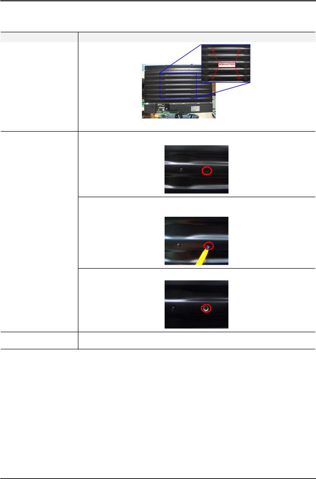
2-4. Wall Mount
*The wall mount's SCREW point have Filim tape for Dust protection(Panel).
So, If User want use Wall mount, Remove Wall mount's Film tape.
Model |
LC3D(LA**C350D1D) |
Wall mount Point
* LC3D Model 's Wall mount point have Film tape
1. Check the wall mount's Film.
2. Delete Wall mount's Flim.
(Push the Flim by Pen or Pinset, and pull the Film)
How to connect wall mount
3. Connect wall mount.
Screw Size |
Type : machine |
|
Size : M4 x L12 (26") / M6 x L12 (32") |
||
|
2-14
|
|
|
2. Product specifications |
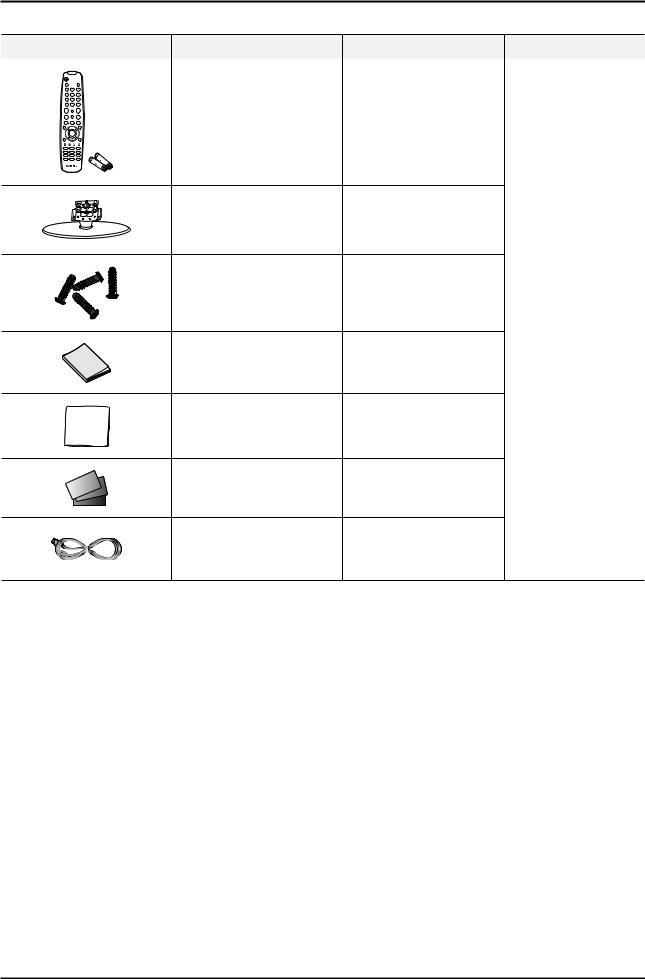
2-5. Accessories |
|
|
|
Product |
Description |
Code. No |
Remark |
|
Remote Control & Batteries |
BN59-01003A |
|
|
(AAA x 2) |
|
|
|
|
|
|
|
|
LC350 19" : BN90-02525A |
|
|
Stand |
LC350 22" : BN90-02281A |
|
|
LC350 32" : BN90-02527A |
|
|
|
|
|
|
|
|
LC350 26" : BN90-02526A |
|
|
Screw |
6002-001294 |
|
|
(19", 22" : 2 Screws |
|
|
|
(for the stand - M4, L16) |
|
|
|
26", 32" : 3 Screws) |
Samsung Electronics |
|
|
|
||
|
|
|
|
|
|
|
Service center |
|
Owner’s Instructions |
BN68-02683A |
|
|
Cleaning Cloth |
BN63-01798B |
|
|
Warranty Card / Registration |
|
|
|
Card / Safety Guide Manual |
AA68-03242M |
|
|
(Not available in all locations) |
|
|
|
Power Cord |
19", 22" : 3903-000172 |
|
2-15

5. Exploded View & Part List
5. Exploded View & Part List
5-1. LA32C350D1 Exploded View
R001A
P001A
M0215
M0014
F001A
SG04
T0175
M0027
T0175
5-1

5. Exploded View & Part List
5-2. LA32C350D1 Parts List
Location No. |
Code No. |
Description & Specification |
Q’ty |
SA/SNA |
Remark |
|
|
|
|
|
|
F001A |
BN96-12859C |
ASSY COVER P-FRONT;LC350 32,SO,ABS+PMMA, |
1 |
SA |
|
|
|
|
|
|
|
M0014 |
BN94-03484P |
ASSY PCB MAIN;MODEL |
1 |
SA |
|
|
|
|
|
|
|
M0027 |
BN96-12870A |
ASSY STAND P-BASE;LC350 32,ABS+PMMA,HB,B |
1 |
SA |
|
|
|
|
|
|
|
M0215 |
BN07-00867A |
LCD-PANEL;T315HA01-DB,CLC4AC1,8bits,32,1 |
1 |
SA |
|
|
|
|
|
|
|
P001A |
BN44-00369A |
AC VSS(I)-TV;PSIV121510A,I32HD_ASM,11mA, |
1 |
SA |
|
|
|
|
|
|
|
R001A |
BN96-12863B |
ASSY COVER P-REAR;LC350 32,SO,HIPS,HB,BK |
1 |
SA |
|
|
|
|
|
|
|
SG04 |
BN61-06270B |
GUIDE-STAND LINK;LC350 32,ABS,HB,BK0020 |
1 |
SA |
|
|
|
|
|
|
|
T0175 |
BN96-13058A |
ASSY SPEAKER P;16ohm,4pin,5W,L:600 R:150 |
1 |
SA |
|
|
|
|
|
|
|
5-2
Loading...