


CLP-325W
Table of contents
 Loading...
Samsung CLP-325W, CLP-321N, CLP-320N, CLP-326, CLP-325 Service Manual
...
Service Manual
Color Laser Printer
CLP-320/325 Series
CLP-320/325/326/320N/321N/325W
- Model series : CLP-320/325
CLP-320N/CLP-321N(Network model)
CLP-325W (Wireless model)
- Speed(Color/Mono) : 4/16 ppm(A4). 4/17ppm(Let)
- Printing resolution : Max. 2,400 x 600 dpi
- Emulation : SPL-C / PCL-6(Network Model)
- Memory : 32MB (USB Model)
256MB (Network/Wireless Model)
- Processor : Jupiter5(360MHz,CLP-320/325/320N/325W)
- Interface : IEEE 802.3,Ethernet(10/100Mbps)
Wireless: IEEE 802.11b/g(Only wireless model)
- Toner Cartridge
• Initial : 1K Toner(K), 0.7K Toner(C,M,Y, each)
• Sales : 1.5K Toner(K), 1K toner(C, M, Y each)
- Printer Life : 100,000 pages
Monthly Max. Duty : 20,000 pages/month
The keynote of Product

1.1 Safety Warning …………………………………………………… 1-1
1.2 Caution for safety ………………………………………………… 1-2
1.3 ESD Precautions ………………………………………………… 1-5
2.1 Product Specications …………………………………………… 2-1
2.1.1 Product Overview …………………………………………… 2-1
2.1.2 Prouduct Specication ……………………………………… 2-2
2.1.3 Model Comparison Table …………………………………… 2-10
2.2 System Overview ………………………………………………… 2-11
2.2.1 System Structure …………………………………………… 2-11
2.2.2 Main PBA Description ……………………………………… 2-18
2.2.3 CRUM ………………………………………………………… 2-25
2.3 S/W Structure and Descriptions ………………………………… 2-26
2.3.1 Architecture ………………………………………………… 2-26
2.3.2 Language Monitor …………………………………………… 2-26
2.3.3 Status Monitor ……………………………………………… 2-26
2.3.4 Network Interface …………………………………………… 2-27
2.3.5 Printer Driver <-> Status Monitor ………………………… 2-27
2.3.6 System F/W Flow …………………………………………… 2-28
2.3.7 CRUM Overview …………………………………………… 2-29
2.3.8 Initailize Flow ………………………………………………… 2-30
3.1 Precautions when replacing parts ……………………………… 3-1
3.1.1 Precautions when assembling and disassembling ……… 3-1
3.1.2 Preautions when handling PBA …………………………… 3-1
3.1.3 Releasing Plastic Latches ………………………………… 3-1
3.2 Parts for Maintenance and Repair ……………………………… 3-2
chapter 1 Precautions
chapter 2 Product Overview
Contents
chapter 3 Disassembly and Reassembly

3.2.1 Replacement interval for parts with a limited life ………… 3-2
3.2.2 Printer Cleaning ……………………………………………… 3-3
3.3 Information Related to Disassembly and Assembly ………… 3-4
3.3.1 Special service parts ……………………………………… 3-4
3.3.2 Screws used in the printer ………………………………… 3-5
3.4 Disassembly Procedure ………………………………………… 3-7
3.4.1 Cover ………………………………………………………… 3-7
3.4.2 ITB …………………………………………………………… 3-9
3.4.3 Fuser unit …………………………………………………… 3-9
3.4.4 HVPS board ………………………………………………… 3-10
3.4.5 Main PBA …………………………………………………… 3-11
3.4.6 SMPS board ………………………………………………… 3-11
3.4.7 LSU …………………………………………………………… 3-12
3.4.8 Holder Pad …………………………………………………… 3-12
3.4.9 Transfer roller ………………………………………………… 3-13
3.4.10 OPE PBA …………………………………………………… 3-14
3.4.11 Pick up roller ……………………………………………… 3-15
4.1 Alignment and Adjustments ……………………………………… 4-1
4.1.1 Control Panel ………………………………………………… 4-1
4.1.2 Jam Removal ………………………………………………… 4-9
4.1.3 Firmware upgrade …………………………………………… 4-13
4.1.4 Periodic Defective Image …………………………………… 4-14
4.1.5 Using the smart pane program …………………………… 4-15
4.1.6 How to use EDC (Engine Diagnostic Control) Mode …… 4-17
4.2 Troubleshooting…………………………………………………… 4-22
4.2.1 Procedure of Checking the Symptoms …………………… 4-22
4.2.2 Troubleshooting Checklist ………………………………… 4-23
4.2.3 Solving General Printing Problems ……………………… 4-24
4.2.4 Solving Print Quality Problems …………………………… 4-32
4.2.5 Common Windows Problems ……………………………… 4-50
4.2.6 Common Macintosh Problems …………………………… 4-51
chapter 4 Alignment and Troubleshooting
Contents

4.2.7 Common Linux Problems ………………………………… 4-52
4.2.8 Major Problems Trouble shooting ………………………… 4-56
5.1 Block Diagram …………………………………………………… 5-1
5.2 Connection Diagram……………………………………………… 5-2
6.1 Tool for Troubleshooting ………………………………………… 6-1
6.2 Acronyms and Abbreviations …………………………………… 6-2
6.3 Select a location for the printer ………………………………… 6-4
6.4 A4 ISO 19798 Standard Pattern ………………………………… 6-5
Contents
chapter 6 Reference Information
chapter 5 System Diagram
attached Parts Catalog
Precautions
Service Manual
1-1
Samsung Electronics
In order to prevent accidents and damages to the equipment please read the precautions listed below
carefully before servicing the product and follow them closely.
1.1 Safety warning
(1) Only to be serviced by a factory trained service technician.
High voltages and lasers inside this product are dangerous. This product should only be serviced by a
factory trained service technician.
(2) Use only Samsung replacement parts.
There are no user serviceable parts inside the product. Do not make any unauthorized changes or
additions to the product as these could cause the product to malfunctions and create an electric shocks
or re hazards.
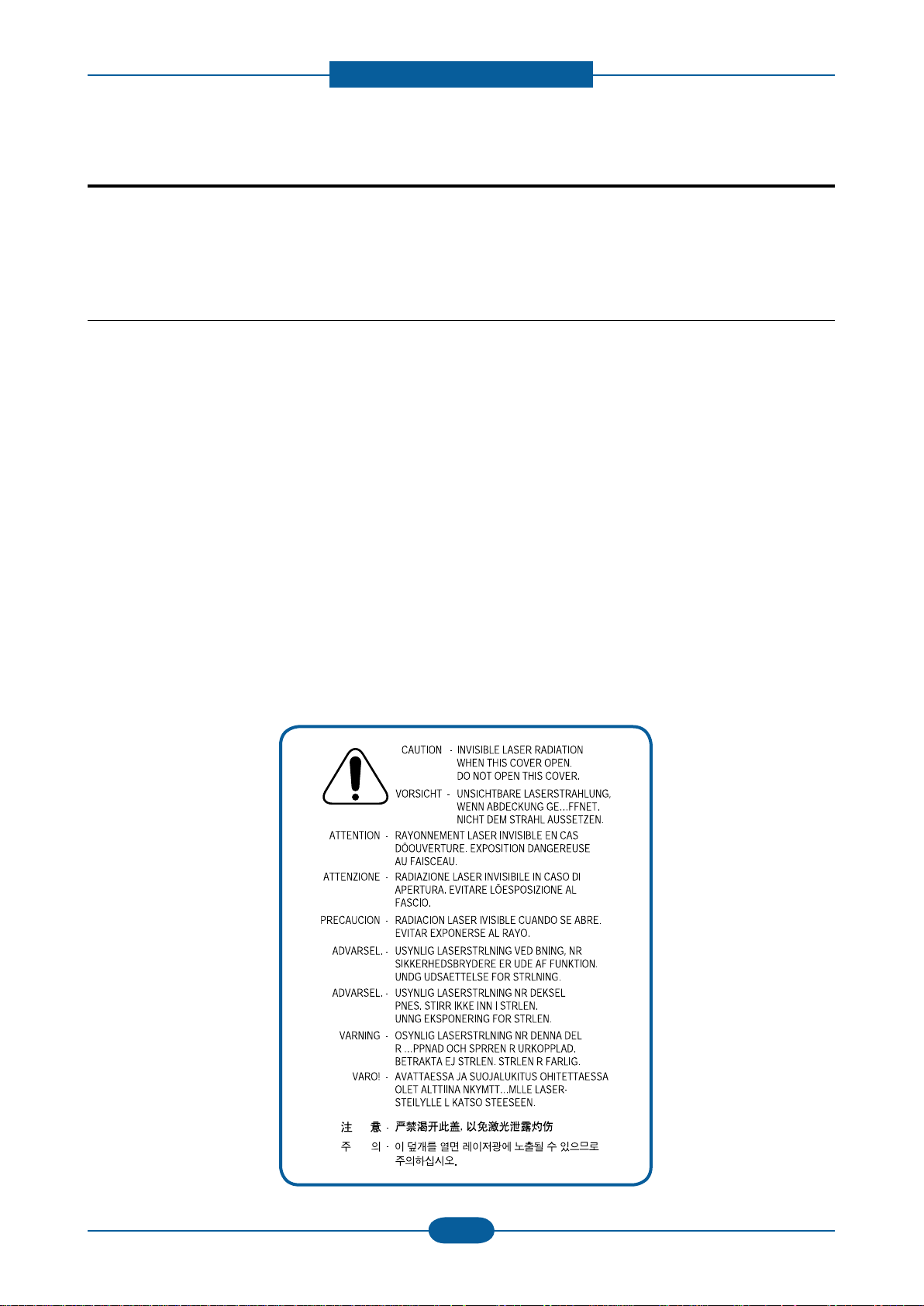
(3) Laser Safety Statement
The product is certied in the U.S. to conform to the requirements of DHHS 21 CFR, chapter 1
Subchapter J for Class 1(1) laser products, and elsewhere, it is certied as a Class I laser product con-
forming to the requirements of IEC 825. Class I laser products are not considered to be hazardous. The
laser system and product are designed so there is never any human access to laser radiation above a
Class I level during normal operation, user maintenance, or prescribed service condition.
Warning >> Never operate or service the product with the protective cover removed from Laser/Scanner
assembly. The reected beam, although invisible, can damage your eyes.
When using this product, these basic safety pre-cautions should always be followed to reduce
risk of re, electric shock, and personal injury.
1. Precautions

Precautions
Service Manual
1-2
Samsung Electronics
1.2 Caution for safety
1.2.1 Toxic material
This product contains toxic materials that could cause illness if ingested.
(1) If the LCD control panel is damaged, it is possible for the liquid inside to leak. This liquid is toxic.
Contact with the skin should be avoided. Wash any splashes from eyes or skin immediately and contact
your doctor. If the liquid gets into the mouth or is swallowed, see a doctor immediately.
(2) Please keep imaging unit and toner cartridge away from children. The toner powder contained in the
imaging unit and toner cartridge may be harmful, and if swallowed, you should contact a doctor.
1.2.2 Electric shock and re safety precautions
Failure to follow the following instructions could cause electric shock or potentially cause a re.
(1) Use only the correct voltage, failure to do so could damage the product and potentially cause a re or
electric shock.
(2) Use only the power cable supplied with the product. Use of an incorrectly specied cable could cause the
cable to overheat and potentially cause a re.
(3) Do not overload the power socket, this could lead to overheating of the cables inside the wall and could
lead to a re.
(4) Do not allow water or other liquids to spill into the product, this can cause electric shock. Do not allow
paper clips, pins or other foreign objects to fall into the product, these could cause a short circuit leading
to an electric shock or re hazard.
(5) Never touch the plugs on either end of the power cable with wet hands, this can cause electric shock.
When servicing the product, remove the power plug from the wall socket.
(6) Use caution when inserting or removing the power connector. When removing the power connector, grip it
rmly and pull. The power connector must be inserted completely, otherwise a poor contact could cause
overheating possibly leading to a re.
(7) Take care of the power cable. Do not allow it to become twisted, bent sharply around corners or wise
damaged. Do not place objects on top of the power cable. If the power cable is damaged it could overheat
and cause a re. Exposed cables could cause an electric shock. Replace the damaged power cable
immediately, do not reuse or repair the damaged cable. Some chemicals can attack the coating on the
power cable, weakening the cover or exposing cables causing re and shock risks.
(8) Ensure that the power sockets and plugs are not cracked or broken in any way. Any such defects should
be repaired immediately. Take care not to cut or damage the power cable or plugs when moving the
machine.
(9) Use caution during thunder or lightning storms. Samsung recommends that this machine be disconnected
from the power source when such weather conditions are expected. Do not touch the machine or the
power cord if it is still connected to the wall socket in these weather conditions.
(10) Avoid damp or dusty areas, install the product in a clean well ventilated location. Do not position the
machine near a humidier or in front of an air conditioner. Moisture and dust built up inside the machine
can lead to overheating and cause a re or cause parts to rust.
(11) Do not position the product in direct sunlight. This will cause the temperature inside the product to rise
possibly leading to the product failing to work properly and in extreme conditions could lead to a re.
(12) Do not insert any metal objects into the machine through the ventilator fan or other part of the casing, it
could make contact with a high voltage conductor inside the machine and cause an electric shock.

Precautions
Service Manual
1-3
Samsung Electronics
1.2.3 Handling precautions
The following instructions are for your own personal safety to avoid injury and so as not to damage the
product.
(1) Ensure the product is installed on a level surface, capable of supporting its weight. Failure to do so could
cause the product to tip or fall.
(2) The product contains many rollers, gears and fans. Take great care to ensure that you do not catch your
ngers, hair or clothing in any of these rotating devices.
(3) Do not place any small metal objects, containers of water, chemicals or other liquids close to the product
which if spilled could get into the machine and cause damage or a shock or re hazard.
(4) Do not install the machine in areas with high dust or moisture levels, beside on open window or close to a
humidier or heater. Damage could be caused to the product in such areas.
(5) Do not place candles, burning cigarettes, etc on the product, These could cause a re.
1.2.4 Assembly / Disassembly precautions
Replace parts carefully and always use Samsung parts. Take care to note the exact location of parts and also
cable routing before dismantling any part of the machine. Ensure all parts and cables are replaced correctly.
Please carry out the following procedures before dismantling the product or replacing any parts.
(1) Check the contents of the machine memory and make a note of any user settings. These will be erased if
the main board or network card is replaced.
(2) Ensure that power is disconnected before servicing or replacing any electrical parts.
(3) Disconnect interface cables and power cables.
(4) Only use approved spare parts. Ensure that part number, product name, any voltage, current or
temperature rating are correct.
(5) When removing or re-tting any parts do not use excessive force, especially when tting screws into
plastic.
(6) Take care not to drop any small parts into the machine.
(7) Handling of the OPC Drum
- The OPC Drum can be irreparably damaged if it exposed to light.
Take care not to expose the OPC Drum either to direct sunlight or to uorescent or incandescent room
lighting. Exposure for as little as 5 minutes can damage the surface of the photoconductive properties
and will result in print quality degradation. Take extra care when servicing the product. Remove the OPC
Drum and store it in a black bag or other lightproof container. Take care when working with the Covers
(especially the top cover) open as light is admitted to the OPC area and can damage the OPC Drum.
- Take care not to scratch the green surface of OPC Drum Unit.
If the green surface of the Drum Cartridge is scratched or touched the print quality will be compromised.

Precautions
Service Manual
1-4
Samsung Electronics
1.2.5 Disregarding this warning may cause bodily injury
(1) Be careful with high temperature components.
The fuser unit works at a high temperature. Use caution when working on the product. Wait for the fuser
to cool down before disassembly.
(2) Be careful when working around the rotating parts.
When operating a product, keep all bodily items and clothing away from moving parts [e.g. ngers, hair,
tie, etc.] (Paper feeding entrance, motor, fan, etc.).
(3) When moving the product :
- When transporting/installing the equipment, employ four persons and be sure to hold the lifting handles.
- Be sure not to hold the movable parts or units (e.g. the control panel, DADF) when transporting the
equipment.
- Be sure to use a dedicated outlet with 110V/220V power input.
- The equipment must be grounded for safety.
- Select a suitable place for installation. Avoid excessive heat, high humidity, dust, vibration and direct
sunlight.
- Provide proper ventilation since the equipment emits a slight amount of ozone.
- The equipment must be installed near the socket outlet and must be accessible.
- Be sure to x and plug in the power cable securely after the installation so that no one trips over it.

Precautions
Service Manual
1-5
Samsung Electronics
1.3 ESD precautions
Certain semiconductor devices can be easily damaged by static electricity. Such components are commonly
called “Electrostatically Sensitive (ES) Devices” or ESDs. Examples of typical ESDs are: integrated
circuits,some eld effect transistors, and semiconductor “chip” components.
The techniques outlined below should be followed to help reduce the incidence of component damage
caused by static electricity.
Caution >>Be sure no power is applied to the chassis or circuit, and observe all other safety precautions.
1. Immediately before handling a semiconductor component or semiconductor-equipped assembly, drain
off any electrostatic charge on your body by touching a known earth ground. Alternatively, employ a
commercially available wrist strap device, which should be removed for your personal safety reasons prior
to applying power to the unit under test.
2. After removing an electrical assembly equipped with ESDs, place the assembly on a conductive surface,
such as aluminum or copper foil, or conductive foam, to prevent electrostatic charge buildup in the vicinity
of the assembly.
3. Use only a grounded tip soldering iron to solder or desolder ESDs.
4. Use only an “anti-static” solder removal device. Some solder removal devices not classied as “anti-static”
can generate electrical charges sufcient to damage ESDs.
5. Do not use Freon-propelled chemicals. When sprayed, these can generate electrical charges sufcient to
damage ESDs.
6. Do not remove a replacement ESD from its protective packaging until immediately before installing it.
Most replacement ESDs are packaged with all leads shorted together by conductive foam, aluminum foil,
or a comparable conductive material.
7. Immediately before removing the protective shorting material from the leads of a replacement ESD, touch
the protective material to the chassis or circuit assembly into which the device will be installed.
8. Maintain continuous electrical contact between the ESD and the assembly into which it will be installed,
until completely plugged or soldered into the circuit.
9. Minimize bodily motions when handling unpackaged replacement ESDs. Normal motions, such as
the brushing together of clothing fabric and lifting one’s foot from a carpeted oor, can generate static
electricity sufcient to damage an ESD.

Product spec and feature
Service Manual
2-1
Samsung Electronics
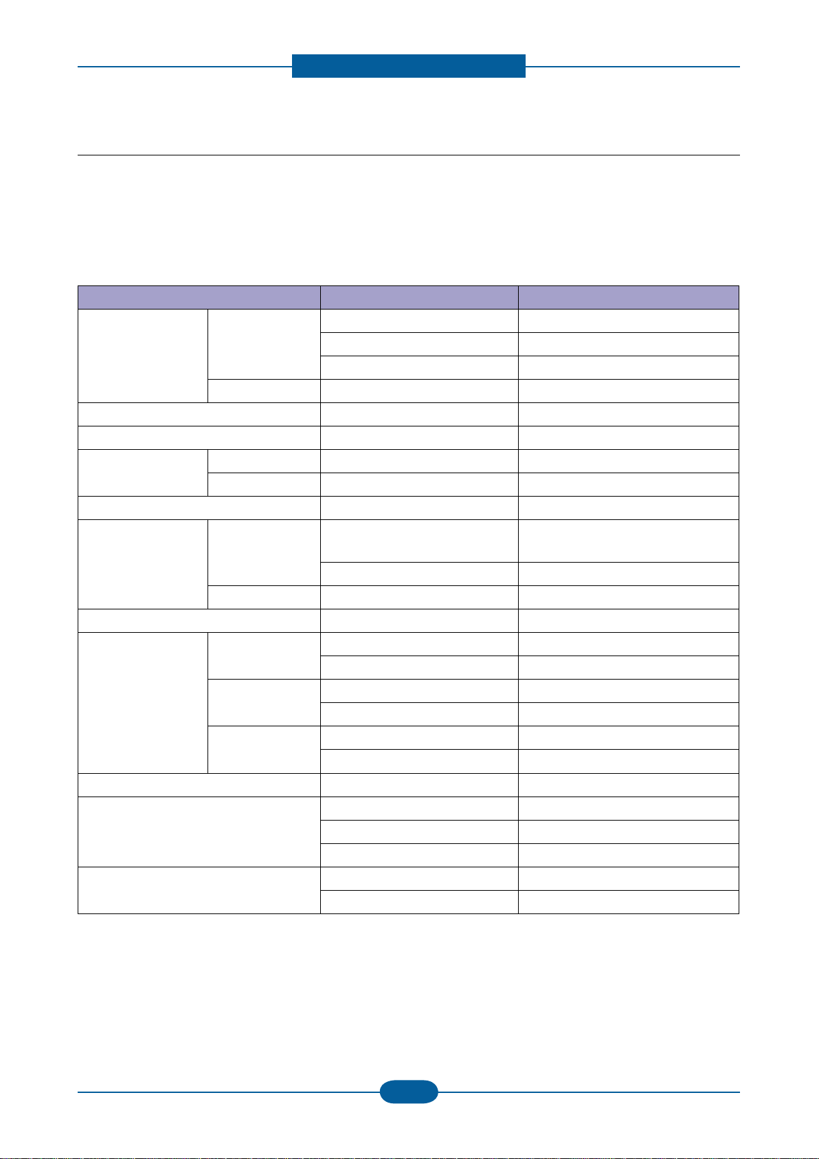
2.1 Product Specications
2.1.1 Product Overview
Item Descriptions
Basic Model CLP-320/325
Series Model CLP-320N : Network Model
CLP-325W : Wireless Model
Main Specication
1. Speed
• Up to 16 ppm in A4 (17 ppm in Letter)
• Up to 4 ppm in A4 (4 ppm in Letter)
2. Printing Resolution
• Max. 2400x600 dpi effective output
3. Processor
• Jupiter5 (360MHz,CLP-320/325/320N/325W)
4. Printer Language Emulations
• SPL-C (CLP-320/325/320N/325W), PCL-6 (320N/325W)
5. Memory
• FLASH ROM
- 2MB : CLP-320/325
- 32MB : CLP-320N/325W
• DDR2 SDRAM
- 32MB : CLP-320/325
- 256MB : CLP-320N/325W
• EEPROM memory
- CLP-325 (8KB)
- CLP-325W (64KB)
- CLP-320N (32KB)
6. Interfaces
• One USB port (CLP-320/325/320N/325W)
• One 10/100 Base T network connector (CLP-320N/325W)
• One IEEE802.11b/g/n (CLP-325W)
7. Control Panel
• No LCD,3 keys ,7single LEDs and 1 dual LEDs
8. Toner cartridge
• Black : 1K (initial) / 1.5K (sales)
• Color : 0.7K (initial) / 1K (sales)
9. Color
• There are two kinds of colors. (Gray and Black)
2. Product spec and feature
Product spec and feature
Service Manual
2-2
Samsung Electronics
2.1.2 Prouduct Specication
Specications are correct at the time of printing. Product specications are subject to change without notice.
See below for product specications.
2.1.2.1 General Print Engine
Item CLP-320/325 CLP-320N/CLP-325W
Print Speed Simplex B&W : 17ppm@Letter B&W : 17ppm@Letter
16ppm@A4 16ppm@A4
Color : 4ppm@A4,.Letter Color : 4ppm@A4,.Letter
Duplex NA NA
Print Emulation SPL-C PCL-6
Auto Emulation Sensing NA NA
Font Type NA NA
Number NA NA
Power Save Yes (5/10/15/30/60/120min.) Yes (5/10/15/30/60/120min.)
Resolution Normal Up to 2400X600dpi Class
(Default 1200x600 dpi)
Up to 2400X600dpi Class
(Default 1200x600 dpi)
Optical: 600x600 Dpi Optical: 600x600 Dpi
RET NA NA
Toner Save NA NA
FPOT From Ready Less than 26 sec ( Color ) Less than 26 sec ( Color )
Less than 14 sec ( B&W ) Less than 14 sec ( B&W )
From Idle Less than 57 sec ( Color ) Less than 57 sec ( Color )
Less than 45 sec (B&W) Less than 45 sec (B&W)
From Cold Boot Less than 57 sec ( Color ) Less than 57 sec ( Color )
Less than 45 sec (B&W) Less than 45 sec (B&W)
Duplex Print NA NA
Printable Area 210 x 297 mm (A4) 210 x 297 mm (A4)
216 x 279 mm (Letter) 216 x 279 mm (Letter)
216 x 355.6 mm (Legal) 216 x 355.6 mm (Legal)
Print Margin Side Margin: 4.23±2mm Side Margin: 4.23±2mm
Top Margin: 4.23±3mm Top Margin: 4.23±3mm
Product spec and feature
Service Manual
2-3
Samsung Electronics
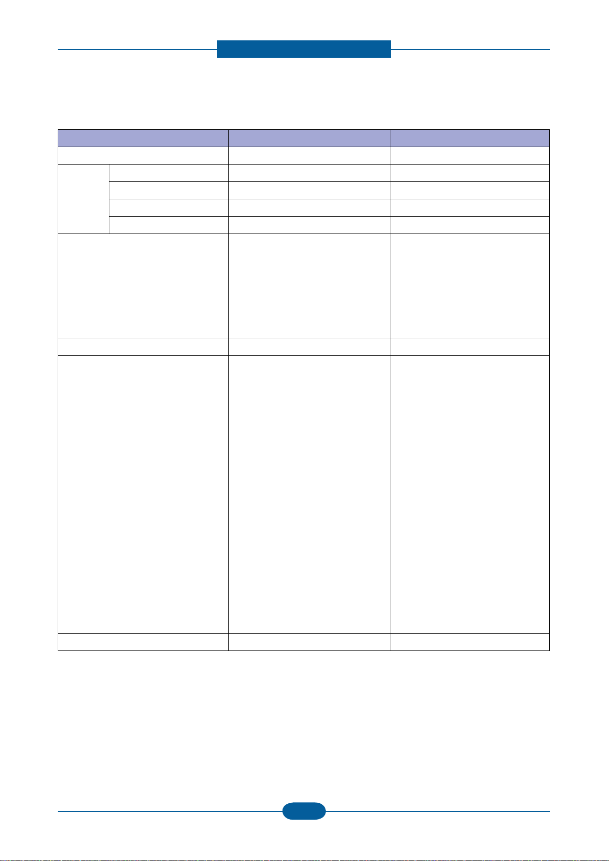
2.1.2.2 Controller & S/W
Item CLP-320/325 CLP-320N/CLP-325W
MPU Jupiter5 (360Mhz) Jupiter5 (360Mhz)
Memory Standard / Max. 256MB/256MB 256MB/256MB
Type DDR2 SDRAM (32MB) DDR2 SDRAM (256MB)
Expand Memory Slot & Type
NA NA
Compression Technology
YES YES
Supporting OS Microsoft Windows:
2000/2003/XP(Include 64bit),Vista
MacOS:10.3 ~ 10.6
Linux(Printer only)OS:
Red Hat 8~9, Fedora Core 1~4
Mandrake 9.2~10.1
SuSE 8.2~9.2
Microsoft Windows:
2000/2003/XP(Include 64bit),Vista
MacOS:10.3 ~ 10.6
Linux(Printer only)OS:
Red Hat 8~9, Fedora Core 1~4
Mandrake 9.2~10.1
SuSE 8.2~9.2
Default Driver SPL-C SPL-C
Driver feature Microsoft Windows:
-Watermark
-N-up printing
-Poster printing
-Manual Dulpex
-Quality(Best,Normal,Draft)
-Color mode(Color, Gray scale)
-Device Color Support
-Color Management Support
[Mac]
-N-up printing
-Quality(Best,Normal,Draft)
-Color mode(Color, Gray scale)
[Linux]
- N-up printing
-Quality(Best,Normal,Draft)
[Common]
-N/W Install
during driver install
Microsoft Windows:
-Watermark
-N-up printing
-Poster printing
-Manual Dulpex
-Quality(Best,Normal,Draft)
-Color mode(Color, Gray scale)
-Device Color Support
-Color Management Support
[Mac]
-N-up printing
-Quality(Best,Normal,Draft)
-Color mode(Color, Gray scale)
[Linux]
- N-up printing
-Quality(Best,Normal,Draft)
[Common]
-N/W Install
during driver install
WHQL Windows 2000 including vista Windows 2000 including vista

Product spec and feature
Service Manual
2-4
Samsung Electronics
Item CLP-320/325 CLP-320N/CLP-325W
Language Locallization [Windows]
- Korean,English,French,Germa
N,Italian,Spanish,Russian,Dutch,
E.Portuguese,B.Portuguese,Fi
Nish,Swedish,Norwegian,Danish
S.Chinese,T.Chinese,Polish,
Hungarian,Greek,Czech,Turkish
[Mac]
- Korean,English,French,GermaN,
Italian,Spanish, S.Chinese,
T.Chinese, E.Portuguese, Dutch
[Linux]
- English Only
[Windows]
- Korean,English,French,Germa
N,Italian,Spanish,Russian,Dutch,
E.Portuguese,B.Portuguese,Fi
Nish,Swedish,Norwegian,Danish
S.Chinese,T.Chinese,Polish,
Hungarian,Greek,Czech,Turkish
[Mac]
- Korean,English,French,GermaN,
Italian,Spanish, S.Chinese,
T.Chinese, E.Portuguese, Dutch
[Linux]
- English Only
Smart Panel USB 320N : USB/Network
325W : USB/Network/Wireless
Network
Default Install Default Install
Network
Management
NA Set IP.SWAS &SWS (Linux, Mac
not support, SWAS&SWS need I
explorer 5.0 or Higher)
NA Management
Smart Thru NA Smart Thru 4
Product spec and feature
Service Manual
2-5
Samsung Electronics
2.1.2.3 Interface
Item CLP-320/325 CLP-320N/CLP-325W
Interface
Parallel NA NA
USB USB 2.0 USB 2.0
Network NA Ethernet 10/100 base Tx
Wireless NA 802.11 b/g (only 325W)
Network
Interface
Protocol NA TCP/IP,IPP,SNMPv2
Network OS NA - Microsoft Windows:
98/ME/2000/XP(32/64Bit)
2003 Server(32/64Bit)/ Vista
- Mac OS: 10.3,10.4(Printing
OnTCP/IP)
- Linux OS: Red Hat 8~9,
Fedora Core 1~4
Mandrake 9.2~10.1 & Suse
8.2~9.2
- Unix HP-UX, Solaris,SunOS
SCO UNIX
User
Interface
LCD NA NA
OP UI Key 3 EA, LED 8EA Key 3 EA, LED 8EA
Sound UI NA NA
Product spec and feature
Service Manual
2-6
Samsung Electronics
2.1.2.4 Paper Handling
Item CLP-320/325 CLP-320N/CLP-325W
Capacity Cassette 130 Sheets @ 80 g/
㎡
Envelop : 5 Sheets
Transparency : 1 Sheets
Label, thick paper : 5 Sheets
GlossyPhoto220 g/
㎡
: 1 Sheets
130 Sheets @ 80 g/
㎡
Envelop : 5 Sheets
Transparency : 1 Sheets
Label, thick paper : 5 Sheets
GlossyPhoto220 g/
㎡
: 1 Sheets
MP Tray NA NA
Option Cassette 80 Sheets @ 80 g/
㎡
Envelop : 5 Sheets
Transparency : 1 Sheets
Label , thick paper : 5 Sheets
GlossyPhoto220 g/
㎡
: 1 Sheets
80 Sheets @ 80 g/
㎡
Envelop : 5 Sheets
Transparency : 1 Sheets
Label , thick paper : 5 Sheets
GlossyPhoto220 g/
㎡
: 1 Sheets
Output Capacity Face Down: 100Sheets/20lb
Envelop ; 5 Sheets
Transparency ; 1 Sheets
Label , thick paper ; 10 Sheets
Face Down: 100Sheets/20lb
Envelop ; 5 Sheets
Transparency ; 1 Sheets
Label , thick paper ; 10 Sheets
Output Full Sensing No No
Duplex Manual Duplex Manual Duplex
Paper Type Cassette A4, A5,A6, Letter, Legal,
Executive, Folio, ISO B5, JIS B5
A4, A5,A6, Letter, Legal,
Executive, Folio, ISO B5, JIS B5
Transparency;(Mono Print Only) Transparency;(Mono Print Only)
MP Tray NA NA
Option Tray NA NA
Paper Weight Cassette 16~43 lb. (60 to 163g/
㎡
) 16~43 lb. (60 to 163g/
㎡
)
Paper Path Standard output Bottom to Top Front (FIFO) Bottom to Top Front (FIFO)
Straight Through NA NA
Paper Size Max 216 x 355.6mm(8.5”x14”) 216 x 355.6mm(8.5”x14”)
Min 76 x 160mm(3”x6.3”) 76 x 160mm(3”x6.3”)
Jam Rate Cassette 1/3,000 1/3,000
Multi-Feed Rate Cassette 1/1,500 1/1,500
Printing Skew Top 1.5/201.4mm (Cassette) 1.5/201.4mm (Cassette)
Side 2.0/270.4mm (Cassette) 2.0/270.4mm (Cassette)
Product spec and feature
Service Manual
2-7
Samsung Electronics
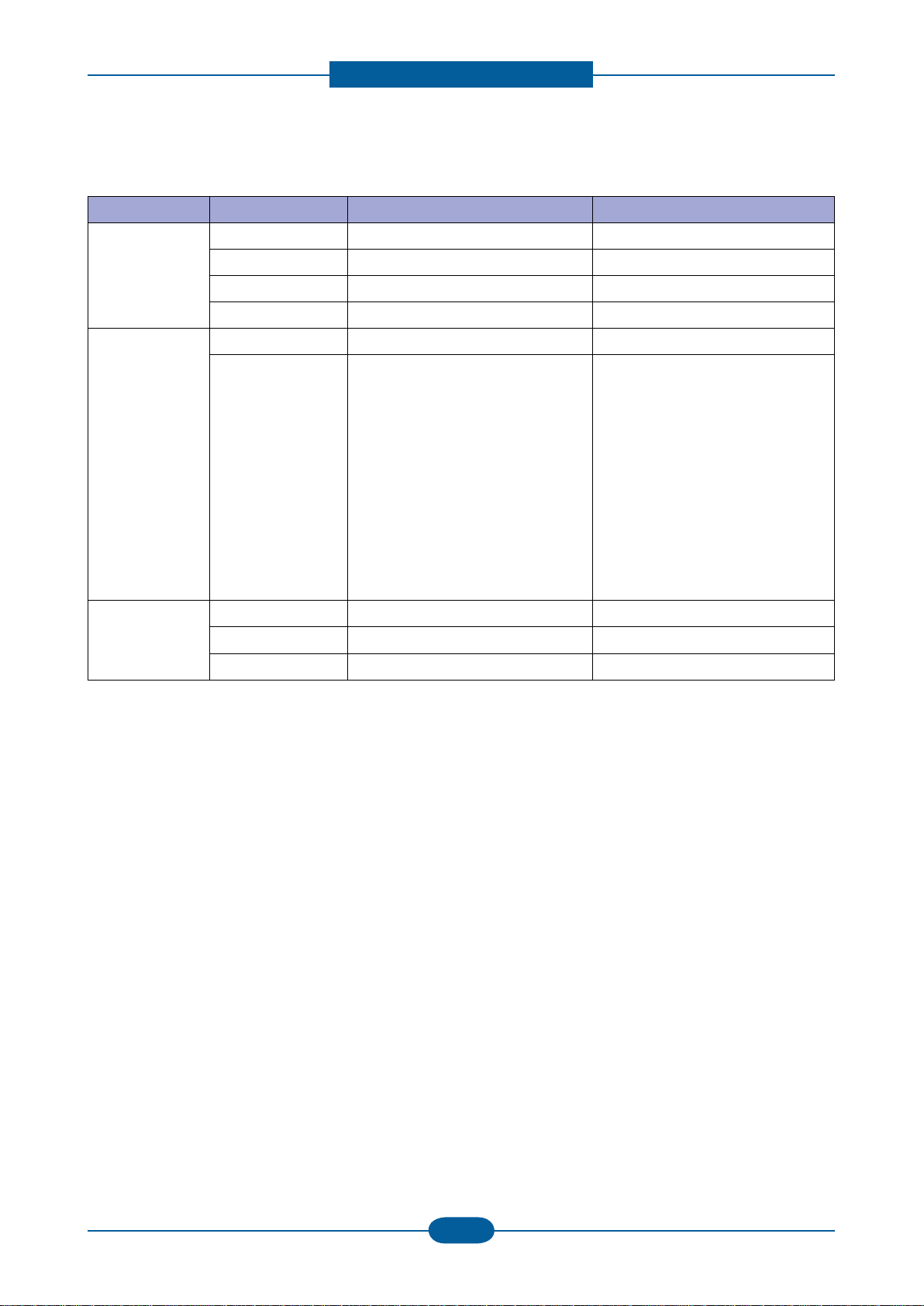
2.1.2.5 Consumables
Item Image Pages Printed Part number Remark
Black Toner
cartridge
Approx. Initial : 1,000 Pages*
Sales : 1,500 Pages*
CLT-K407S,
CLT-K4072S (Black)
CRU
Color Toner
cartridge
Approx. Initial : 700 Pages*
Sales : 1,000 Pages*
CLT-C407S,
CLT-C4072S (Cyan)
CLT-M407S,
CLT-M4072S (Magenta)
CLT-Y407S,
CLT-Y4072S (Yellow)
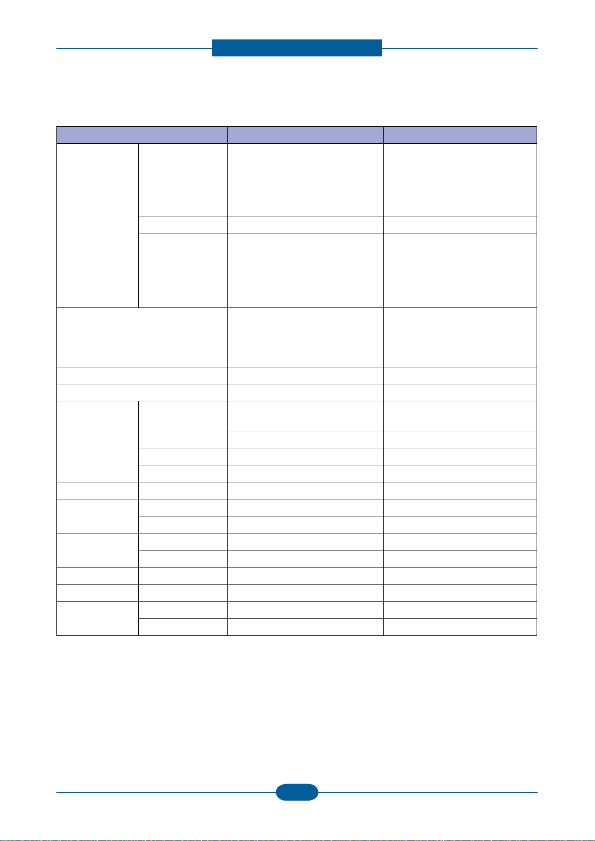
Imagine unit
Approx. 24000 images* CLT-R407
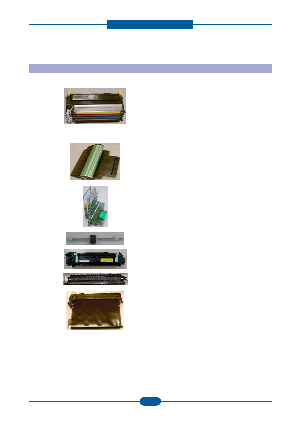
Waste Toner
Approx. 10,000 images CLT-W409
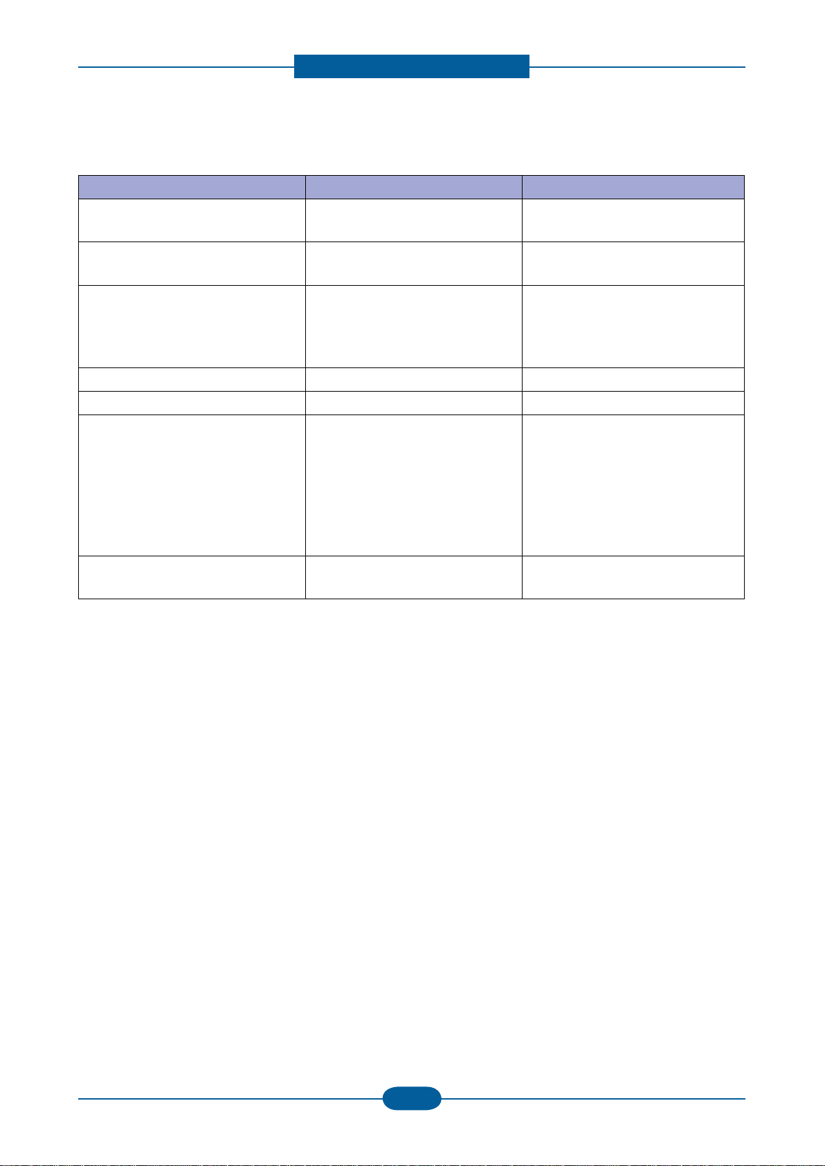
Pick-up roller
Approx. 50,000 pages JC97-03028A FRU
Fuser unit
Approx. 50,000 pages(B&W)
/ 12,500 pages (Color)
JC91-00978A (220V)
JC91-00997A (110V)
T2 roller
Approx. 50,000 pages(B&W)
/ 12,500 pages (Color)
JC95-01197A
ITB
Approx. 50,000 pages(B&W)
/ 12,500 pages (Color)
JC96-05874A
* Average A4-/letter-sized page count based on Std. ISO 19798 of individual colors on each page.
Usage conditions and print patterns may cause results to vary.
Product spec and feature
Service Manual
2-8
Samsung Electronics
2.1.2.6 Reliability & Service
Item CLP-320/325 CLP-320N/CLP-325W
Max Monthly Duty 20,000 image
(Color: 16,000/ Mono: 4,000)
20,000 image
(Color: 16,000/ Mono: 4,000)
SET Life Cycle 100,000image or 5 years
whichever comes rst
100,000image or 5 years
whichever comes rst
MTBF 40,000 images
(color 32,000 images and black
8,000 images : total 40,000
image)
40,000 images
(color 32,000 images and black
8,000 images : total 40,000 image)
MTTR <30 min. <30 min.
Real-time Clock No No
System record Total image count
Total page count (color/mono)
Imaging unit Information
Transfer roller life
Transfer belt life
Toner information
Tray roller life
Total image count
Total page count (color/mono)
Imaging unit Information
Transfer roller life
Transfer belt life
Toner information
Tray roller life
Minimum System Requirement Pentium-
Ⅱ
400MHZ, 64MB RAM,
300MB HDD, Internet Explorer 5.0
Pentium-
Ⅱ
400MHZ, 64MB RAM,
300MB HDD, Internet Explorer 5.0
Product spec and feature
Service Manual
2-9
Samsung Electronics
2.1.2.7 Environment
Item CLP-320/325 CLP-320N/CLP-325W
Power
Consumption
Ready Less than 160W Less than 160W
Average Less than 350W
(Currency:5A(110V)/3A(220V)
Less than 350W
(Currency:5A(110V)/3A(220V)
Max/Peak 700W/1KW 700W/1KW
Sleep/Power off Less than 5W/0.45W Less than 8W/0.45W (325W)
Less than 6W (320N)
Power Supply Input Voltage AC 110V~127V, AC 220V~240V
AC 120V/AC 220V(EXP version)
AC 110V~127V, AC 220V~240V
AC 120V/AC 220V(EXP version)
Input Frequency 50 / 60Hz(+/- 3Hz) 50 / 60Hz(+/- 3Hz)
Noise Printing Mono : 46dBA
Color : 48dBA
Mono : 46dBA
Color : 48dBA
Standby Background noise level Background noise level
Sleep Background noise level Background noise level
Warm Up Time From Cold Status
(At rated volt)
Less than 35 seconds Less than 35 seconds
Temperature Operating 10~32.5
℃
10~32.5
℃
Storage (Un-Packed)
5~35
℃
5~35
℃
Storage (Packed) -20~50
℃
-20~50
℃
Humidity Operating 20 ~ 80% RH 20 ~ 80% RH
Storage (Un-Packed)
20 ~ 80% RH 20 ~ 80% RH
Storage (Packed) 10~90% RH 10~90% RH
Altitude Normal: 0~3000ft (0~1000m) Normal: 0~3000ft (0~1000m)
High: 3001~6600ft( ~2000m) High: 3001~6600ft( ~2000m)
Higher: 6601~9900ft( ~3000m) Higher: 6601~9900ft( ~3000m)
Highest;9901~13000ft( ~4000m) Highest;9901~13000ft( ~4000m)
2.1.2.8 Accessory
Item CLP-320/325 CLP-320N/CLP-325W
Quick setup guide Yes Yes
Owner’s manual Yes Yes
S/W CD ROM 1 : for Driver 1 : for Driver
2 : for Network
S/W
1 CD for Driver, SmarThru 4
1 CD for Driver, SmartThru 4, EUG 1 CD for Driver, SmartThru 4, EUG
Toner Cartridge 4 EA (0.7K/0.5K yield ISO 19752
5% Coverage)
4 EA (0.7K/0.5K yield ISO 19752
5% Coverage)
Power Cable 1 EA 1 EA
Printer Cable 1 EA 1 EA
Product spec and feature
Service Manual
2-10
Samsung Electronics
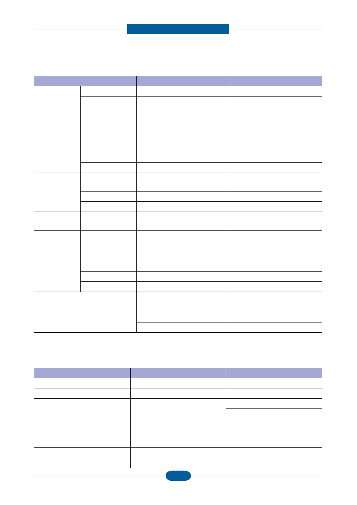
2.1.3 Model Comparison Table
Samsung Samsung HP
CLP-325/325W CLP-315/315W CP-1215
Image
Print speed (M/C) 16/4ppm 16/4ppm 12/8ppm
FPOT 14/26 sec 14/26 sec 24/30 sec
Resolution Up to 2400 dpi Up to 2400 dpi 2400 HP ImageREt
CPU 375 MHz 375 MHz 264 MHz
Std Memory 32 MB (256 MB) 32 MB 16 MB (16MB)
Emulation PCL6(325W), SPL-C SPL-C GDI
Duplex Manual Manual Manual
Paper Handling 130 CST 150 CST 150 CST
Output 80 sheet 80 sheet 125
Noise
45dB/ 47dB
(Color/Black)
45dB/ 47dB
(Color/Black)
47dB
Max. Monthly Duty 20,000 20,000 25,000
Size 388 x 313 x 243 388 x 314 x 237 398.7 x 452 x 253
Weight 11kg (TBD) 11kg 17.6 kg
Interface USB 2.0, Wireless(325W) USB 2.0, Wireless(315W) USB 2.0
Toner 1.5K/1K (1K/0.7K) 1.5K/1K (1K/0.7K) 2.2K/1.4K(0.75K)
Etc
1W Soft Power
Print Screen Button (325)
DLNA Printing (325W)
WPS Button (325W)
9 LED
Product spec and feature
Service Manual
2-11
Samsung Electronics
2.2 System Overview
This chapter describes the functions and operating principles of the main components.
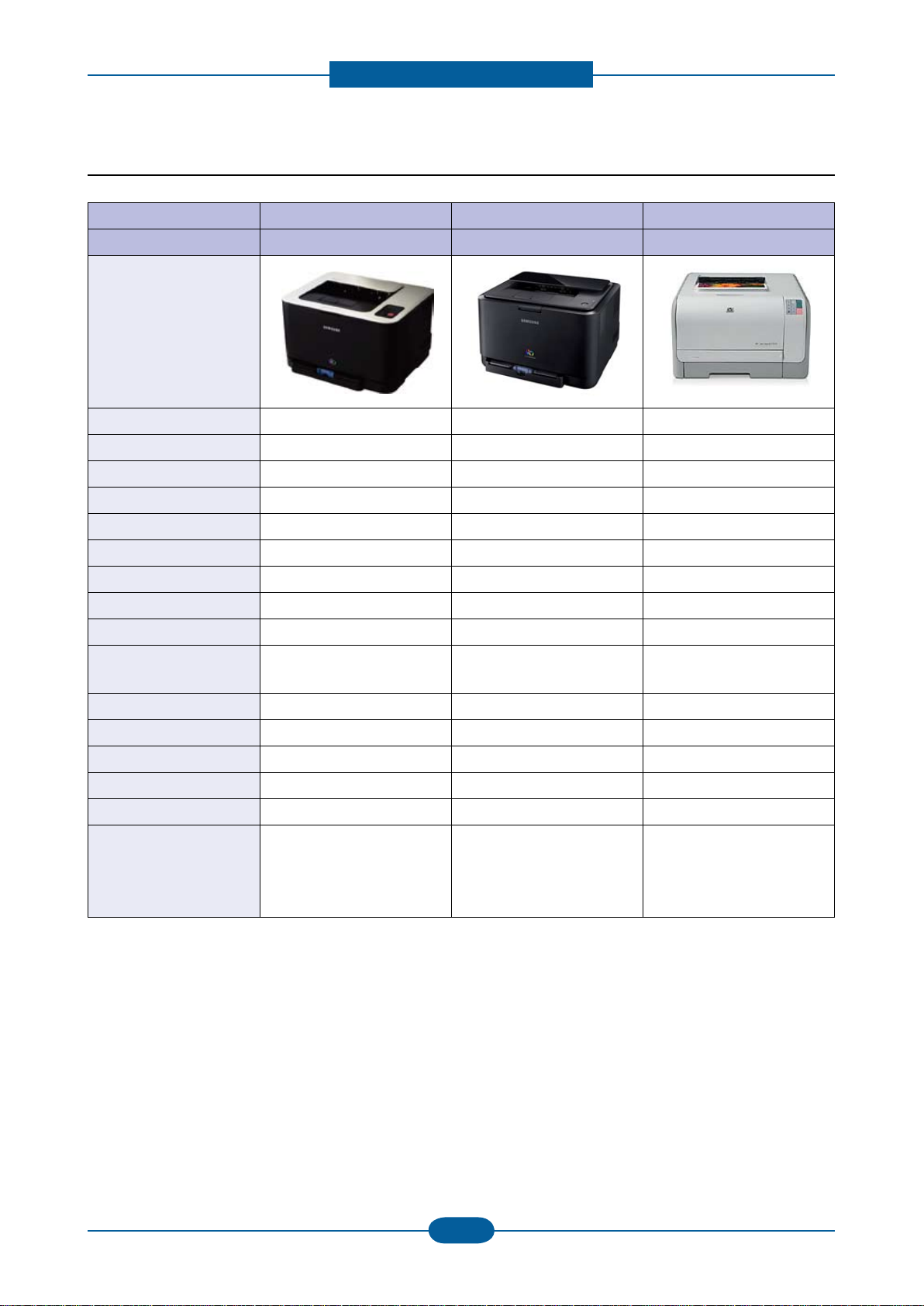
2.2.1 System Structure
The Printer function consists of the Engine part and the Main Controller part, and the Engine part consists
of the Mechanical part comprising a Frame, Feeding, Developing, Driving, Transferring, Fusing, and Cabinet
and the Electrical part comprising a SMPS, a HVPS, a LSU, and some facilities in the Main Controller to
control the Engine part for printing.
2.2.1.1 Main Parts of System
ITB
OPC
DEVE Y
DEVE M
DEVE C
DEVE K
LSU
Cassette
Fuser
Stacking Area
T2 Roller
Regi.
Roller
T1 Roller
Pick up
Roller
Waste
Tank
ITB
OPC
DEVE Y
DEVE M
DEVE C
DEVE K
LSU
Cassette
Fuser
Stacking Area
T2 Roller
Regi.
Roller
T1 Roller
Pick up
Roller
Waste
Tank
Product spec and feature
Service Manual
2-12
Samsung Electronics
①
Cassette
• Feeding Method : Cassette Type
• Feeding Standard : Center Loading
• Feeding Capacity : Cassette 150 Sheets(75g/
㎡
, 20lb Pa per Standard)
• No Manual Feeder
• Paper Detecting Sensor : Photo Sensor (Empty, Registration, Exit)
• Paper Size Sensor : None
②
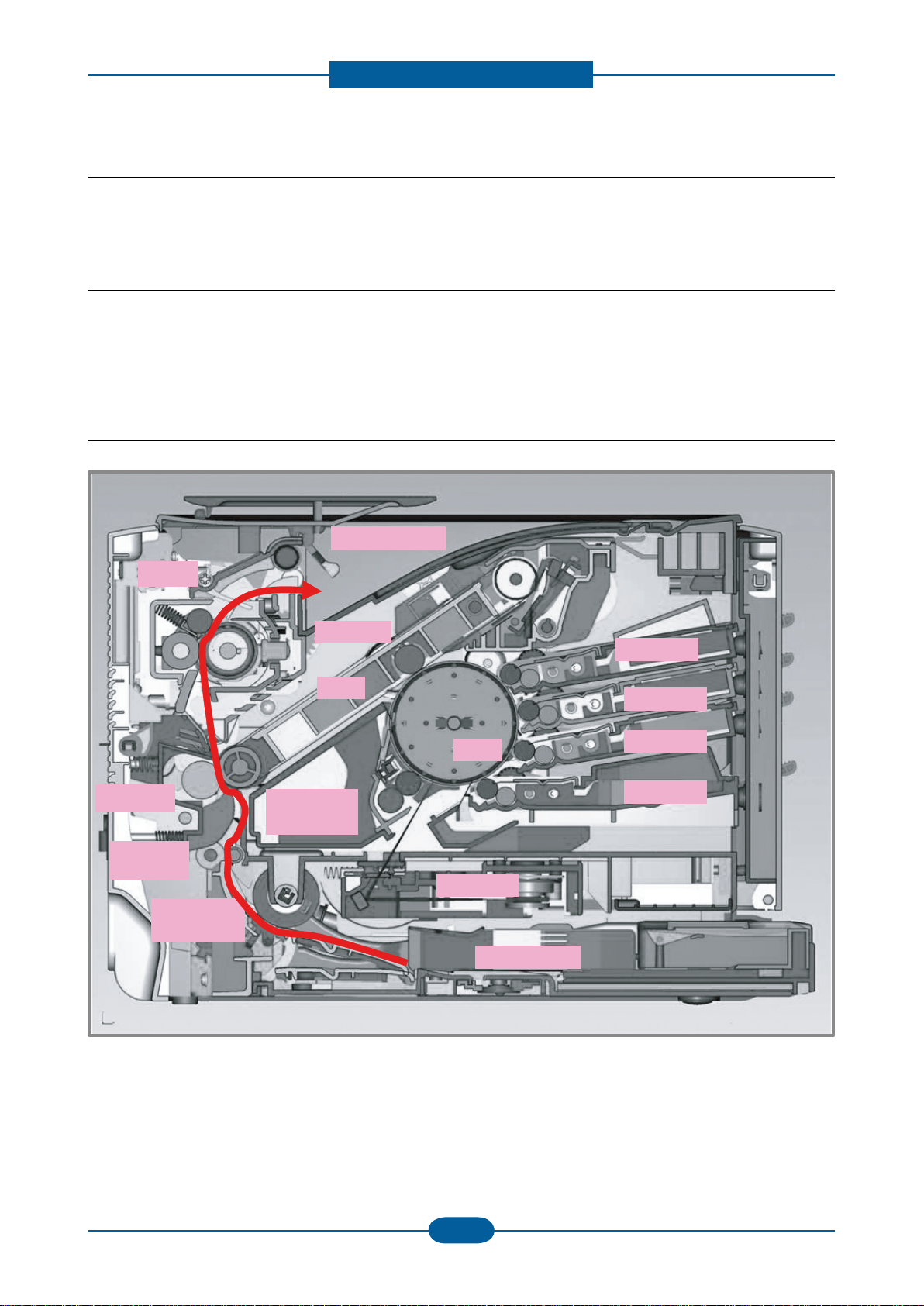
LSU(Laser Scan Unit)
The LSU unit is controlled by video controller. It scans the video data received from video controller with
laser beam by using the rotation principle of the polygon mirror to create the latent image on the OPC
drum. It is the core part of LBP.
The OPC drum rotates as the same speed as the paper feeding speed. It creates the /HSYNC signal and
sends it to the engine when the laser beam of the LSU reaches the end of the polygon mirror, and the
engine detects the /HSYNC signal to arrange the vertical line of the image on the paper. After detecting
the /HSYNC signal, the image data is sent to the LSU to arrange the its margin on the paper.
• Consisted of LD(Laser Diode) and Polygon Motor Control.
Error Phenomenon
Polygon Motor Error The Rotation of Polygon Motor can not reach stable
Hsync Error Though the rotation of Polygon Motor reach stable, the signal of Hsync is
not occurred
Product spec and feature
Service Manual
2-13
Samsung Electronics
③
2nd Transfer Ass’y
• The life span: Print over 100,000 sheets (in 15~30 )
• Specication: Similar to CLP-300 Series
④
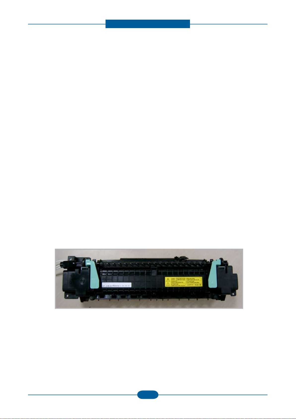
Fuser Ass’y
This unit consists of Heat Roller, a Thermostat and a Thermistor. It melts and fuses the toner, transferred
by the transfer roller onto the paper, by applying pressure and high temperature to complete printing job.
* Heat Lamp : Kunckle Type
* Fusing system : 3-Roll Fusing type
- Heat roller : Pipe type (Lamp inside)
- Pressure roller
- Pressure roller Shaft
* Thermistor - Temperature-Measuring Device
* Thermostat - Critical Temperature-Detecting Device
* The life span – 100k(black)/color(25k)
Thermostat
When a heat lamp is overheated, a Thermostat cuts off the main power to prevent over-heating.
- Non-Cotact type Thermostat
Heat roller
The heat roller transfers the heat from the lamp to apply a heat on the paper. The surface of a heat
roller is coated with Teon, so toner does not stick to the surface.
Pressure roller
A pressure roller mounted under a heat roller is made of a silicon resin, and the surface also is coated
with Teon. When a paper passes between a heat roller and a pressure roller, toner adheres to the surface
of a paper permanently.
Product spec and feature
Service Manual
2-14
Samsung Electronics
⑤
&
⑥
ITB(Intermediate Transfer Belt) & 1st Transfer Roller
• The life span: Print over Approx. 50,000 pages(B&W) / 12,500 pages (Color)
• The ITB unit includes 1st Transfer Roller
⑦
&
⑧
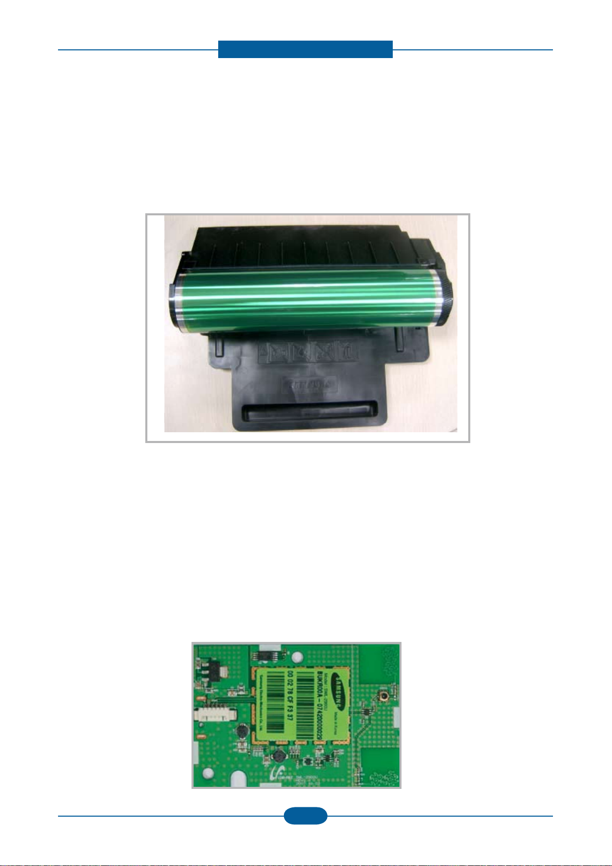
OPC(Organic Photo-Conductor) & Developer
• The life span: Print over 50,000 Images (Both)
• Imagine Unit consists of 4 kinds of Developer , OPC, and Deve. Main Frame
⑨
Toner Kits
• The life span: Color -> 1000 images (Std. ISO 19798 Print-Out)
Black -> 1500 images (Std. ISO 19798 Print-Out)
⑩
Driver Ass’y
• It is a power delivery unit by gearing
• By driving the motor, it supplies the power to the feeding unit, the fusing unit, and the distributing unit.
• The Main Motor is similar to CLP-310 Series Main Motor.
⑪
Wireless PBA (Only CLP-325W)
• CLP-325W model has a Wireless PBA to use wireless network.
Product spec and feature
Service Manual
2-15
Samsung Electronics
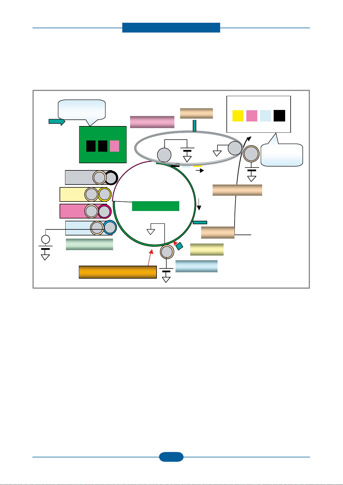
2.2.1.2 EP Process
- Structure of EP Process
Charger
Developer
Laser Scanning Unit
OPC
ITB Unit
Eraser
Blade
Blade
Media Path
P2: Image
on Media
P1: Image
on OPC
~
Charger
Developer
Laser Scanning Unit
OPC
ITB Unit
Eraser
Blade
Blade
Media Path
P2: Image
on Media
P1: Image
on OPC
~~

Product spec and feature
Service Manual
2-16
Samsung Electronics
①
Charging
• Conductive Roller charging
• Applied voltage : -1.1kV
• Charge acceptance : -520V
• OPC coating thickness : 21um
• OPC diameter : Φ60mm
• Eraser system
1. Organic Photoconductor is charged to uniform voltage by conductive roll charging method
2. No ozone is produced because corona is not used
3. Charger roll is cleaned with cleaning roll
4. Toner remained on OPC after T1 process is cleaned by cleaning blade and retrieved into waste toner box
by auger and belt driving mechanism
②
Exposing
• One polygon motor ( 6 facet )
• Single beam LD (1ea)
• LD wavelength : 785nm
• Polygon motor rpm : 29685
• LSU energy : 0.25uJ/cm^2
• OPC exposed potential : -50V
1. Exposing is implemented by laser striking on to OPC with uniform potential
2. Laser beam is modulated according to image to be printed that is from PC
3. Latent Image is formed on OPC, which is developed with toner
③
Developing
• Non-magnetic, mono component
• Non-contact development
• Developing bias : DC + AC
• AC peak to peak : 1.5 ~ 2.0kV
• Roller diameter : Φ10mm
• Process speed ratio : 1.2 (OPC=1.0)
• Color order : Y -> M -> C -> K
1. Only latent image formed by exposing process is developed with toner
2. AC + DC Voltage is being used to develop toner into latent image on OPC because non-contact
developing method is adopted
3. Y, M, C, and K Images are sequentially developed onto OPC and transferred onto Intermediate Transfer
Belt (hereafter ITB) to form a color image on ITB
4. Toner Bottles are used to supply toner into developer compartment
5. Toner level is being sensed to control toner supply from toner bottle to developer

Product spec and feature
Service Manual
2-17
Samsung Electronics
④
Transfer 1
• Multi-pass transfer
• Indirect transfer
• Transfer voltage : 0.5 ~ 2.0kV (controllable)
• Roller diameter : Φ14mm
• Transfer unit life : 100K images
1. Developed Image on OPC is transferred onto ITB by T1 Process
2. T1 Voltage is positive which attract toner to ITB
3. 4 times of T1 process is required to make a color image on ITB, which means multi-pass process
4. ITB has a hole as a ducial mark for timing. Engine control for color image is synchronous with it, ITB
Home Sensing Signal
⑤
Transfer 2
• Indirect transfer
• Transfer voltage : 1 ~ 4.0kV (controllable)
• Roller diameter : Φ18.6mm
• Transfer unit life : 100 K images
1. Color image formed on ITB is transferred onto media by T2 process
2. T2 voltage is also positive to get color image moved onto media
3. Toner remained on ITB after T2 process is cleaning by ITB cleaning blade and collected and
4. Transported and retrieved into waste toner box by auger and belt driving system
5. T2 Roll is engaged when color image is being transferred onto media. Otherwise it is disengaged. Clutch
is used for driving T2 Roll engagement and disengagement
⑥
Fusing
• 3 Roll system
-> short warm-up time (35sec)
• Post Pressure Roll
1. Color Image on media is melted down and xed into media by fusing process
Product spec and feature
Service Manual
2-18
Samsung Electronics
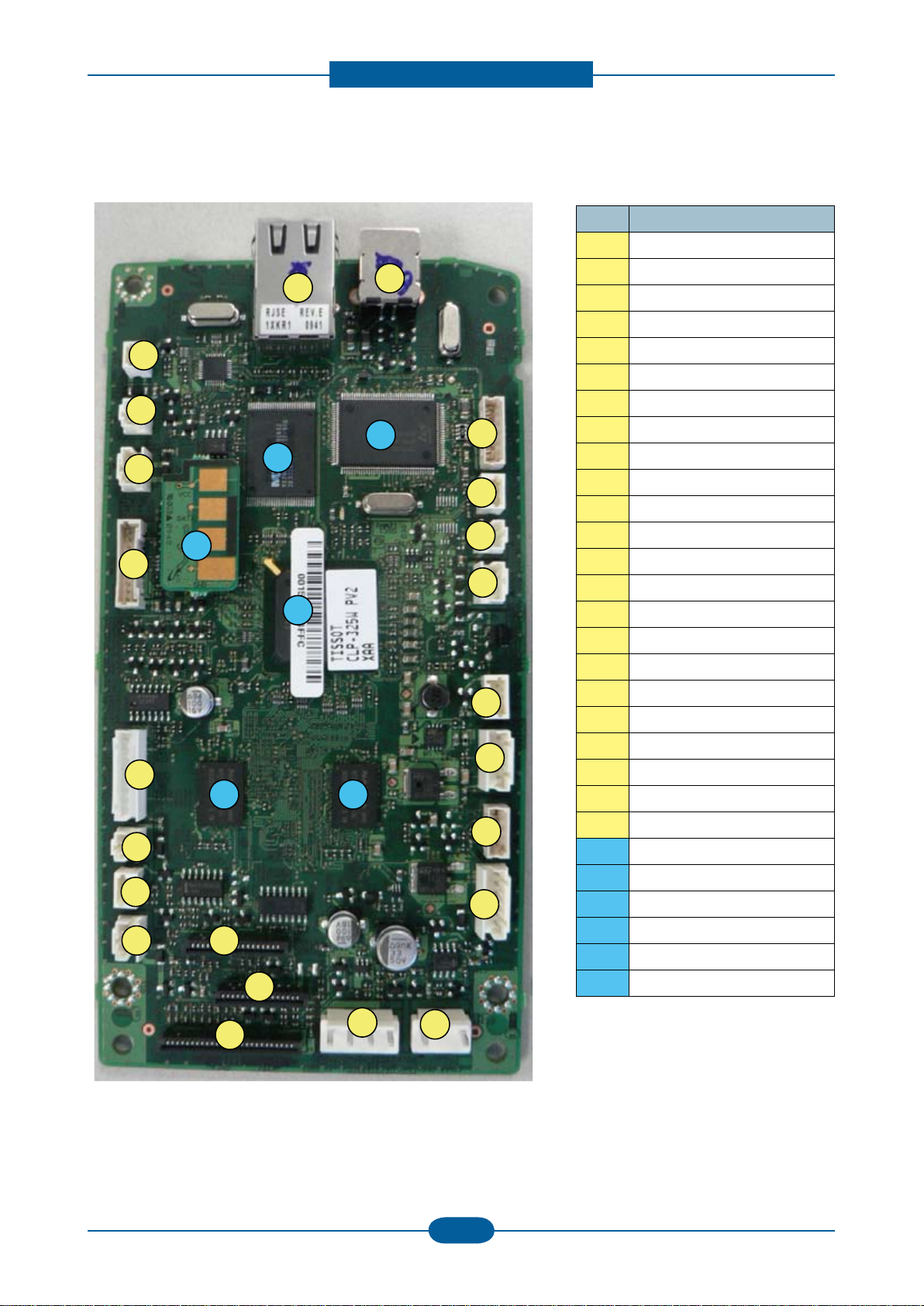
2.2.2 Main PBA Description
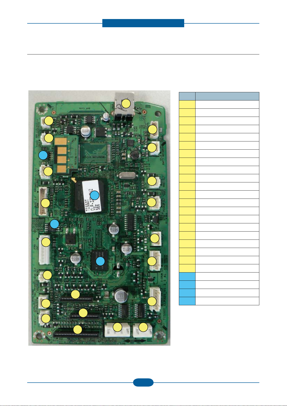
2.2.2.1 Main Controller PBA
- CLP-320/325
14
13
11
3
16
2
D
6
9
10
19
18
1
22
A
B
4
8
5
7
20
17
15
23
C
NO. NAME
1 Deve home CON.(3P)
2 ITB CLT(3P)
3 Deve CLT(2P)
4 Debug(4P)
5 T2 CLT(3P)
7 BLDC I/F(10P)
8 JTAG (8P)
9 Regi CLT.(2P)
10 Fuser CLT(2P)
12 Fuser(2P)
13 SMPS_P(4P)
14 OPE & ITB (18P)
15 HVPS(26P)
16 LSU Con.(16P)
17 Empty Sensor (3P)
18 Key PTL(4P)
19 Cover OPEN (2P)
20 USB (4P)
21 Pickup CLT. (3P)
22 S-CRUM I/F (5P)
23 SMPS_S (6P)
A CPU(Jupiter5)
B DDR2 (32MB)
C Serial FLASH(2MB)
D EEPROM
Product spec and feature
Service Manual
2-19
Samsung Electronics
- CLP-320N/325W
28
1
11
20
4
12
D
26
22
10
15
30
6
5
A
B
3
16
18
8
19
29
7
9
F
B
E
24
27
NO. NAME
1 OPE & ITB (18P)
3 W-LAN (6P) (W Only)
4 Ethernet (8P)
5 S-CRUM I/F (5P)
6 Debug(4P)
7 LSU Con.(16P)
8 JTAG (8P)
9 SMPS_S (6P)
10 Fuser(2P)
11 SMPS_P(4P)
12 Deve home CON.(3P)
15 USB (4P)
16 Empty (3P)
18 T2 CLT(3P)
19 Regi CLT.(2P)
20 Deve CLT(2P)
22 ITB CLT(3P)
24 Fuser CLT(2P)
26 Pickup CLT. (3P)
27 BLDC I/F(10P)
28 HVPS(26P)
29 Key PTL(4P)
30 Cover OPEN (2P)
A CPU(Jupiter5)
B DDR2 (64MB X 2)
C Nor FLASH(32MB)
D EEPROM (Under PBA)
E PHY Chip
F USB IC(W Only)
Product spec and feature
Service Manual
2-20
Samsung Electronics
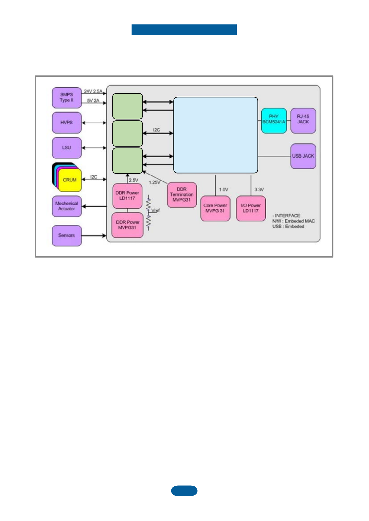
2.2.2.3 Main PBA Description
Jupiter5
A Proprietary SoC, Jupiter5, executes and controls all jobs and functions to be required for
printing. To do these all jobs, the Jupiter5 incorporates all H/W blocks as follows.
▪ CPU Core ARM 926ESJ, I/D-Cache 16/16KB , Up to 400MHz
▪ System Bus Internally 32-bit width, Up to 120MHz
▪ MEM Controller DDR1/2, 16-bit width, 166MHz, 4-Bank, 128MB Space/bank
▪ ROM Controller 16-bit width, 4-bank, 16MB Space/bank
▪ CODEC Controller JBIG 4-ch Decoder and 2-ch Encoder, 1-ch JPEG
▪ Image Processor Processing Scan Image
▪ MAC Controller 10/100Mbps Full IEEE 802.3 Compatibility
▪ USB Controller USB2.0, Device or Host
▪ UART Controller
▪ I2C Controller
▪ Interrupt Controller
▪ Misc. Controller ADC, DAC, PWM, Step Motor Control and so on
▪ Voltage Core 1.0V, I/O 3.3V
▪ Package 416PBGA
Flash Memory
Used to store System Programs including the Operating System.
▪ Type NOR Flash
▪ Bus 16-bit width
▪ Size : 2MB (CLP-320/325)
32MB (CLP-320N/325W)
CPU
Jupiter5(360MHz)
FLASH
EEPROM
24C64
DDR2 SDRAM

Product spec and feature
Service Manual
2-21
Samsung Electronics
System Memory
Used as a Printing buffer for printing, a Scan buffer for scanning, a ECM Buffer for System
Working Area.
▪ Type DDR2 SDRAM
▪ Bus 16-bit 166MHz
▪ Size 32MB (320/325) / 256MB(320N/325W)
CRU Control
Used to store the printing and operating information into a Security EEPROM in 4 CRUs, Y,M,C
and K Imaging Cartridge, respectively by the CHORUS3.
▪ Access I2C Bus Ch.2 400KHz
▪ Security Size 2K-bit
System Information Control
Used to store the system operating information needed at printing into a EEPROM in the Main Controller by
the CHORUS3.
▪ Access I2C Bus Ch.1 400KHz
▪ EEPROM Size 64Kbit
OPE Interface
Used to control the OPE by the CHORUS3. Through CHORUS3’s GPIO pins, all LEDs and Keys in the OPE
are controlled.
I/O Port
Used to receive or transmit some data from/to the Host.
▪ USB Device USB2.0 High speed 480Mbps
▪ Network Ethernet 10/100-Base Tx
(note) The Network only equipped at CLP-320N/325N, not CLP-320/325.
Engine Control
Used to control all parts to be required at printing by the CHORUS 3.
▪ Sensors Paper Empty
Paper Registration
Waste Toner Bottle
Paper Exit
Temperature sensors
Etc.
▪ Clutches(Solenoid) Paper Pick Up
Paper Registration
Etc.
▪ Motor 1 BLDC
▪ LSU
▪ Fuser Control the Fuser’s temperature
▪ HVPS Control the high voltage outputs
▪ ADC Reading the Fuser’s temperature and the high voltage outputs’ feedback
▪ Cover Open Sensing
Loading...