


Operator’s Manual
Electric Chain Saw / Pole Saw
TABLE OF CONTENTS
|
Service . . . . . . . . . . . . . . . . . . . . . . . . . . . . . . . . . . . . . . . . . . . . . |
. .1 |
|
Safety . . . . . . . . . . . . . . . . . . . . . . . . . . . . . . . . . . . . . . . . . . . . . . |
.2 |
RM1025P / RM1025SPS |
Know Your Unit . . . . . . . . . . . . . . . . . . . . . . . . . . . . . . . . . . . . . . . |
.9 |
|
Essential Terms and Definitions . . . . . . . . . . . . . . . . . . . . . . . . . . |
11 |
|
Specifications . . . . . . . . . . . . . . . . . . . . . . . . . . . . . . . . . . . . . . . . |
12 |
|
Assembly . . . . . . . . . . . . . . . . . . . . . . . . . . . . . . . . . . . . . . . . . . . . |
13 |
|
Starting and Stopping . . . . . . . . . . . . . . . . . . . . . . . . . . . . . . . . . . |
15 |
|
Operation . . . . . . . . . . . . . . . . . . . . . . . . . . . . . . . . . . . . . . . . . . . . |
16 |
|
Maintenance . . . . . . . . . . . . . . . . . . . . . . . . . . . . . . . . . . . . . . . . . |
22 |
|
Cleaning and Storage . . . . . . . . . . . . . . . . . . . . . . . . . . . . . . . . . . |
28 |
|
Troubleshooting . . . . . . . . . . . . . . . . . . . . . . . . . . . . . . . . . . . . . . . |
29 |
|
Warranty . . . . . . . . . . . . . . . . . . . . . . . . . . . . . . . . . . . . . . . . . . . . |
30 |
SAVE THESE INSTRUCTIONS
SERVICE
DO NOT RETURN THIS UNIT TO THE RETAILER. PROOF OF
PURCHASE WILL BE REQUIRED FOR WARRANTY SERVICE.
For assistance regarding the assembly, controls, operation or maintenance of the unit, please call the Customer Support Department at 1-866-206-2707 in the United States or 1-877-696-5533 in Canada. Additional information about the unit can be found on our website at www.remingtonpowertools.com.
For service, please call the Customer Support Department to obtain a list of authorized service dealers near you. Service on this unit, both within and after the warranty period, should only be performed by an authorized and approved service dealer. When servicing, use only identical replacement parts.
All information, illustrations, and specifications in this manual are based on the latest product information available at the time of printing. We reserve the right to make changes at any time without notice.
Copyright© 2014 MTD SOUTHWEST INC, All Rights Reserved.
IMPORTANT: Read this manual thoroughly before using this product. Follow all instructions.
769-10045 / 00 |
07/14 |

SAFETY
The purpose of safety symbols is to attract your attention to possible dangers. The safety symbols, and their explanations, deserve your careful attention and understanding. The safety warnings do not by themselves eliminate any danger. The instructions or warnings they give are not substitutes for proper accident prevention measures.
SYMBOL MEANING
DANGER: Signals an EXTREME hazard.
Failure to obey a safety DANGER signal WILL result in serious injury or death to yourself or to others.
WARNING: Signals a SERIOUS hazard.
Failure to obey a safety WARNING signal CAN result in serious injury to yourself or to others.
CAUTION: Signals a MODERATE hazard.
Failure to obey a safety CAUTION signal MAY result in property damage or injury to yourself or to others.
NOTE: Advises you of information or instructions vital to the operation or maintenance of the equipment.
CALIFORNIA PROPOSITION 65
WARNING: This product contains a chemical known to the State of California to cause cancer, birth defects or other reproductive harm.
Read the operator’s manual and follow all warnings and safety instructions. Failure to do so can result in serious injury to the operator and/or bystanders.
• IMPORTANT SAFETY INSTRUCTIONS •
GENERAL POWER TOOL SAFETY WARNINGS
WARNING:Read all safety warnings and all instructions. Failure to follow the warnings and instructions may result in electric shock, fire and/or serious injury.
Save all warnings and instructions for future reference.
The term “power tool” in the warnings refers to your mains-operated (corded) power tool or battery-operated (cordless) power tool.
1)Work Area Safety
a)Keep work area clean and well lit. Cluttered or dark areas invite accidents.
b)Do not operate power tools in explosive atmospheres, such as in the presence of flammable liquids, gases or dust.
Power tools create sparks which may ignite the dust or fumes.
c)Keep children and bystanders away while operating a power tool. Distractions can cause you to lose control.
2)Electrical Safety
a)Power tool plugs must match the outlet. Never modify the plug in any way. Do not use any adapter plugs with earthed (grounded) power tools. Unmodified plugs and matching outlets will reduce risk of electric shock.
b)Avoid body contact with earthed or grounded surfaces such as pipes, radiators, ranges and refrigerators. There is an increased risk of electric shock if your body is earthed or grounded.
c)Do not expose power tools to rain or wet conditions. Water entering a power tool will increase the risk of electric shock.
d)Do not abuse the cord. Never use the cord for carrying, pulling or unplugging the power tool. Keep cord away from heat, oil, sharp edges or moving parts. Damaged or entangled cords increase the risk of electric shock.
e)When operating a power tool outdoors, use an extension cord suitable for outdoor use. Use of a cord suitable for outdoor use reduces the risk of electric shock.
f)If operating a power tool in a damp location is unavoidable, use a ground fault circuit interrupter (GFCI) protected supply. Use of a GFCI reduces the risk of electric shock.
3)Personal Safety
a)Stay alert, watch what you are doing and use common sense when operating a power tool. Do not use a power tool while you are tired or under the influence of drugs, alcohol or medication. A moment of inattention while operating power tools may result in serious personal injury.
b)Use personal protective equipment. Always wear eye protection. Protective equipment such as dust mask, non-skid safety shoes, hard hat, or hearing protection used for appropriate conditions will reduce personal injuries.
c)Prevent unintentional starting. Ensure the switch is in the off-position before connecting to power source and/or battery pack, picking up or carrying the tool. Carrying power tools with your finger on the switch or energizing power tools that have the switch on invites accidents.
d)Remove any adjusting key or wrench before turning the power tool on. A wrench or a key left attached to a rotating part of the power tool may result in personal injury.
e)Do not overreach. Keep proper footing and balance at all times. This enables better control of the power tool in unexpected situations.
2
f)Dress properly. Do not wear loose clothing or jewelry. Keep your hair, clothing and gloves away from moving parts. Loose clothes, jewelry or long hair can be caught in moving parts.
g)If devices are provided for the connection of dust extraction and collection facilities, ensure these are connected and properly used. Use of dust collection can reduce dust-related hazards.
4)Power Tool Use and Care
a)Do not force the power tool. Use the correct power tool for your application. The correct power tool will do the job better and safer at the rate for which it was designed.
b)Do not use the power tool if the switch does not turn it on and off. Any power tool that cannot be controlled with the switch is dangerous and must be repaired.
c)Disconnect the plug from the power source and/or the battery pack from the power tool before making any adjustments, changing accessories, or storing power tools. Such preventive safety measures reduce the risk of starting the power tool accidentally.
d)Store idle power tools out of the reach of children and do not allow persons unfamiliar with the power tool or these instructions to operate the power tool. Power tools are dangerous in the hands of untrained users.
e)Maintain power tools. Check for misalignment or binding of moving parts, breakage of parts and any other condition that may affect the power tool’s operation. If damaged, have the power tool repaired before use. Many accidents are caused by poorly maintained power tools.
f)Keep cutting tools sharp and clean. Properly maintained cutting tools with sharp cutting edges are less likely to bind and are easier to control.
g)Use the power tool, accessories and tool bits etc. in accordance with these instructions, taking into account the working conditions and the work to be performed. Use of the power tool for operations different from those intended could result in a hazardous situation.
5)Service
a)Have your power tool serviced by a qualified repair person using only identical replacement parts. This will ensure that the safety of the power tool is maintained.
Chain saw safety warnings:
•Keep all parts of the body away from the saw chain when the chain saw is operating. Before you start the chain saw, make sure the saw chain is not contacting anything. A moment of inattention while operating chain saws may cause entanglement of your clothing or body with the saw chain.
•Always hold the chain saw with your right hand on the rear handle and your left hand on the front handle. Holding the chain saw with a reversed hand configuration increases the risk of personal injury and should never be done.
•Hold the power tool by insulated gripping surfaces only, because the saw chain may contact hidden wiring or its own cord. Saw chains contacting a “live” wire may make exposed metal parts of the power tool “live” and could give the operator an electric shock.
•Wear safety glasses and hearing protection. Further protective equipment for head, hands, legs and feet is recommended. Adequate protective clothing will reduce personal injury by flying debris or accidental contact with the saw chain.
•Do not operate a chain saw in a tree. Operation of a chain saw while up in a tree may result in personal injury.
•Always keep proper footing and operate the chain saw only when standing on fixed, secure and level surface.
Slippery or unstable surfaces such as ladders may cause a loss of balance or control of the chain saw.
•When cutting a limb that is under tension be alert for spring back. When the tension in the wood fibers is released the spring loaded limb may strike the operator and/or throw the chain saw out of control.
•Use extreme caution when cutting brush and saplings. The slender material may catch the saw chain and be whipped toward you or pull you off balance.
•Carry the chain saw by the front handle with the chain saw switched off and away from your body. When transporting or storing the chain saw always fit the guide bar cover.
Proper handling of the chain saw will reduce the likelihood of accidental contact with the moving saw chain.
•Follow instructions for lubricating, chain tensioning and changing accessories. Improperly tensioned or lubricated chain may either break or increase the chance of kickback.
•Keep handles dry, clean, and free from oil and grease.
Greasy, oily handles are slippery causing loss of control.
•Cut wood only. Do not use chain saw for purposes not intended. For example: do not use chain saw for cutting plastic, masonry or non-wood building materials. Use of the chain saw for operations different than intended could result in a hazardous situation.
Causes and operator prevention of kickback:
Kickback may occur when the nose or tip of the guide bar touches an object, or when the wood closes in and pinches the saw chain in the cut.
Tip contact in some cases may cause a sudden reverse reaction, kicking the guide bar up and back towards the operator.
Pinching the saw chain along the top of the guide bar may push the guide bar rapidly back towards the operator.
Either of these reactions may cause you to lose control of the saw which could result in serious personal injury. Do not rely exclusively upon the safety devices built into your saw. As a chain saw user, you should take several steps to keep your cutting jobs free from accident or injury.
Kickback is the result of tool misuse and/or incorrect operating procedures or conditions and can be avoided by taking proper precautions as give below:
•Maintain a firm grip, with thumbs and fingers encircling the chain saw handles, with both hands on the saw and position your body and arm to allow you to resist kickback forces. Kickback forces can be controlled by the operator, if proper precautions are taken. Do not let go of the chain saw.
•Do not overreach and do not cut above shoulder height.
This helps prevent unintended tip contact and enables better control of the chain saw in unexpected situations.
•Only use replacement bars and chains specified by the manufacturer. Incorrect replacement bars and chains may cause chain breakage and/or kickback.
•Follow the manufacturer’s sharpening and maintenance instructions for the saw chain. Decreasing the depth gauge height can lead to increased kickback.
3

READ ALL INSTRUCTIONS BEFORE OPERATING
WARNING: When using the unit, all safety instructions must be followed. Please read these instructions before operating the unit in order to ensure the safety of the operator and any bystanders. Please keep these instructions for later use.
GENERAL SAFETY WARNINGS
•Read the instructions carefully. Be familiar with the controls and proper use of the unit. Know how to stop the unit and disengage the controls quickly.
•Do not operate this unit when tired, ill or under the influence of alcohol, drugs or medication.
•Never allow children to operate the unit. Never allow adults to operate the unit without proper instruction.
•All guards and safety attachments must be installed properly before operating the unit.
•Inspect the unit before use. Replace damaged parts. Make sure all fasteners are in place and secure. Replace parts that are cracked, chipped, or damaged in any way. Do not operate the unit with loose or damaged parts.
•Be aware of risk of injury to the head, hands and feet.
•Carefully inspect the area before starting the unit. Remove rocks, broken glass, nails, wire, string and other objects that may be thrown or become entangled with the unit.
•Clear the area of children, bystanders and pets; keep them outside a 50-foot (15 m) radius, at a minimum (Fig. A). Even then, they are still at risk from thrown objects. Encourage bystanders to wear eye protection. If you are approached, stop the unit immediately.
Fig. A
SAFETY WARNINGS FOR ELECTRIC UNITS
•Do not expose the unit to rain or wet conditions.
•Do not handle the unit, cords, or plugs with wet hands.
•Avoid dangerous environments. Do not operate the unit in the rain, in wet conditions or on wet surfaces. Moisture is a shock hazard.
•To reduce the risk of electric shock, avoid body contact with grounded conductors, such as metal pipes or wire fences.
•Do not operate the unit in explosive atmospheres, such as in the presence of flammable liquids, gases or dust.
•A nameplate on the unit indicates the voltage used. Never connect the unit to an AC voltage that differs from this voltage.
•Use of an improper extension cord could result in a risk of fire, electric shock or electrocution.
WARNING: To reduce the risk of electrical shock, use only extension cords approved for outdoor use, such as an extension cord of cord type SW-A, SOW-A, STW-A, STOW- A, SJW-A, SJOW-A, SJTW-W or SJTOW-A. Extension cords are available from your local retailer. Use only roundjacketed extension cords approved for outdoor use.
•Do not use multiple extension cords.
•Make sure the extension cord is heavy enough to carry the current drawn by the unit. An undersized extension cord will cause a drop in line voltage, resulting in a loss of power and overheating. If in doubt, use the next heavier gauge cord. The smaller the gauge number, the heavier the cord.
MINIMUM WIRE SIZE FOR EXTENSION CORDS FOR 120 VOLT APPLIANCES USING 6-12 AMPS
Cord Length (ft.) |
25 |
50 |
100 |
150 |
|
|
|
|
|
Wire Size (AWG) |
18 |
16 |
12 |
10 |
|
|
|
|
|
•Make sure the cords are in good condition. Inspect the power cord and extension cord periodically. Look closely for deterioration, cuts or cracks in the insulation. If a cord is damaged in any manner while plugged in, disconnect the cord from both the outlet and the unit. Do not use a damaged cord. Damaged cords should be replaced or repaired by an authorized service dealer.
•Do not abuse cords. Never pull or carry the unit by a cord. Keep cords away from heat, oil, water, sharp edges, and moving objects. Always grasp the plug when disconnecting a cord.
•Never modify a plug, cord or outlet in any way.
•Ground Fault Circuit Interrupter (GFCI) protection should be provided on the circuit(s) or outlet(s) to be used with this unit. For an extra measure of safety, use receptacles with built-in GFCI protection.
WARNING: To reduce the risk of electric shock, use a Ground Fault Circuit Interrupter (GFCI) with a tripping current of 30 mA or less.
•Keep cords away from the operating area. Position cords so that they will not be caught or entangled on branches or other obstacles during operation.
•To prevent tripping, keep cords away from the operator's feet.
•Always disconnect the unit from the power source when it is not in use.
•Prevent disconnection of the power cord from the extension cord during operation by using a plug-receptacle retaining strap, connector, or by making a knot (Fig. B).
4

Extension Cord |
Unit Power Cord |
Fig. B
•To reduce the risk of electrical shock, this unit has a polarized plug (one blade is wider than the other). Polarized plugs require polarized extension cords. The plug fits into the extension cord only one way. If the plug does not fit fully into the extension cord, reverse the plug. If the plug still does not fit, obtain another polarized extension cord. Polarized extension cords require polarized wall outlets. The extension cord fits into the wall outlet only one way. If the extension cord does not fit fully into the wall outlet, reverse the plug. If the extension cord still does not fit, contact a qualified electrician to install the proper wall outlet.
•This is a double-insulated unit. Two systems of insulation are provided instead of grounding. There is no grounding provided and no means of grounding should be added to the unit. Servicing a double-insulated unit requires extreme care and knowledge of the system. Service should only be performed by authorized service personnel. Replacement parts for a doubleinsulated unit must be identical to the parts they replace. Failure to have a double-insulated unit repaired by an authorized service technician with identical replacement parts could result in serious injury.
•Since the unit is double-insulated, a 2-wire extension cord (one without a ground) may be used. However, a 3-wire extension cord (one with a ground) that uses a NEMA-type connector (parallel blade, U ground) is recommended.
WHILE OPERATING
•Wear safety glasses or goggles that meet current ANSI / ISEA Z87.1 standards and are marked as such. Wear ear/hearing protection when operating this unit. Wear a face mask or dust mask if the operation is dusty. Use a hard hat or other type of safety helmet.
•Wear safety boots and protective gloves. Wear heavy, snugfitting clothes, including long pants and a long-sleeve shirt. Do not wear loose clothing, jewelry, short pants, sandals or go barefoot. Secure hair above shoulder level.
•Make sure the saw chain is not in contact with anything before starting the unit.
•Use the unit only in daylight or good artificial light.
•Avoid accidental starting. The operator and unit must be in a stable position while starting. Refer to Starting and Stopping.
•Use the right tool. Only use this tool for its intended purpose: to cut wood. Do not use the unit for cutting plastic, masonry or other non-wood building materials. Only use the unit as described in this manual.
•Keep all body parts away from the saw chain when the unit is running. Do not touch or try to stop moving parts.
•Do not force the unit, especially near the end of a cut. It will do a better, safer job when used at the intended rate.
•Always turn the unit off when operation is delayed, when setting the unit down or when carrying the unit from one location to another. Make sure all moving parts come to a complete stop.
•When carrying the unit, hold it away from the body, with the guide bar positioned to the rear. Cover the guide bar and saw chain with the scabbard when carrying the unit.
•When carrying the unit as a chain saw: Hold the unit by the front handle.
•When carrying the unit as a pole saw: Adjust the telescoping pole to the shortest position. Hold the unit by the pole, at the center of balance.
•If the unit strikes or becomes entangled with a foreign object, stop the motor immediately, disconnect the unit from the power source and allow the unit to cool. Then, check for damage. If damaged, do not restart or operate the unit until it is repaired. Do not operate the unit with loose or damaged parts.
•Use only original equipment manufacturer (OEM) replacement parts and accessories for this unit. These are available from your authorized service dealer. Use of any other parts or accessories could lead to serious injury to the user, or damage to the unit, and void the warranty.
•Keep the unit clean. Carefully remove vegetation and other debris that could block moving parts.
•If the unit starts to vibrate abnormally, stop the motor immediately, disconnect the unit from the power source and allow the unit to cool. Then, inspect the unit for the cause of the vibration. Vibration is generally an indicator of trouble.
•Keep the work area clean. Cluttered areas invite injuries. Do not start cutting until the work area is clear and free from obstructions. Make sure there is secure footing and a planned retreat path from falling trees or branches.
•Do not cut near electrical cables or power lines (Fig. A). Keep at least 50 feet (15 m) away from all power lines.
•Do not stand directly under limbs being trimmed (Fig. A). Always take a position out of the path of falling debris.
•Do not use a pole saw to fell a tree. Use a standard chain saw for this application.
•For safer, more effective performance, make sure the guide bar and chain are properly cleaned, lubricated, tightened and sharpened. Check the guide bar and chain at frequent intervals for proper adjustment.
•When cutting a limb that is under tension, use extreme caution. When the tension is released, the limb could spring back and strike the operator, causing severe injury or death.
5

•Use extreme caution when cutting small-sized brush and saplings, as slender material may catch the saw chain and be whipped toward the operator or pull the operator off balance.
•This saw is classified by UL as a Class 2C saw in accordance with CSA Z62.1-03. It is intended for infrequent use by homeowners, cottagers and campers, and for general applications such as clearing, pruning, cutting firewood, etc. It is not intended for prolonged use. If the intended use involves prolonged periods of operation, this may cause circulatory problems in the user’s hands due to vibration.
•Do not operate the unit in a tree or on a ladder unless specifically trained to do so.
•Do not use the unit in the presence of flammable liquids or gases.
•Do not attempt operations beyond the operator’s capacity or experience.
•Do not operate a unit that is damaged, improperly adjusted or not completely and securely assembled. Make sure moving parts stop when the unit is turned off. Do not use the unit if it does not turn on and off properly. Have defective parts replaced by an authorized service dealer.
•Avoid starting the unit unintentionally. Make sure the lock-off button is in the locked position before connecting or disconnecting the unit and the power source. Never carry the unit with fingers on the throttle control.
•Do not use the unit if the lock-off button and throttle control do not start and stop the unit.
KICKBACK SAFETY
WARNING: Kickback may occur when the nose or tip of the guide bar touches an object, or when the wood closes in and pinches the saw chain in the cut. In some cases, tip contact may cause a lightening-fast reverse action, kicking the guide bar rapidly back towards the operator. Pinching the saw chain along the top of the guide bar may push the guide bar rapidly back towards the operator. Either of these reactions may cause a loss of control over the saw, which could result in serious injury to the user. Contact with foreign objects within the wood can also induce a loss of chain saw control.
Understanding Kickback
A basic understanding of kickback can help reduce or eliminate the element of surprise and the chance of kickback-related injury. Sudden surprise contributes to accidents.
•Rotational Kickback can happen when the upper tip of the guide bar contacts an object while the chain is moving (Fig. C). This can cause the chain to dig into the object and momentarily stop moving. The guide bar is then kicked up and back toward the operator in a lightning-fast reverse reaction.
•Linear Kickback can happen when the wood on either side of a cut closes in and pinches the moving saw chain along the top of the guide bar (Fig. D). This can cause the chain to instantly stop. The chain force is then reversed, causing the saw to move in the opposite direction, sending the saw straight back toward the operator.
•Pull-In can happen when the moving chain on the bottom of the guide bar hits a foreign object inside the wood. This can cause the chain to suddenly stop. The saw is then pulled forward and away from the operator, which could potentially result in the loss of control of the saw.
Rotational
Kickback
Kickback
Danger Zone
Saw Chain
Direction
Fig. C
Pinch
Linear
Kickback
Fig. D
6
Kickback Safety Precautions
Take the following steps to reduce the chance of accident or injury:
•Do not rely exclusively upon the safety devices built into the unit.
•Do not overreach. Always keep proper footing and balance. Take extra care when working on stairs, steep slopes or inclines.
•When the unit is used as a chain saw: Do not cut above shoulder height.
•When the unit is used as a pole saw: Do not extend arms above shoulder height.
•Do not make cuts with the tip of the guide bar.
•Make sure the area of operation is free from obstructions. Do not let the tip of the guide bar contact any object, such as a log, branch, the ground or other obstruction.
•Always inspect the wood before cutting. Foreign objects could damage the unit or cause serious personal injury. Never cut through nails, metal rods, railroad ties or pallets.
•Do not operate the unit with one hand! Serious injury to the operator, helpers or bystanders may result from one-handed operation. This unit is intended for two-handed use. Always grip the unit firmly with both hands when the unit is running. Do not let go. A firm grip will help maintain control of the unit and reduce the chance of kickback.
•When the unit is used as a chain saw: Hold the front handle with the left hand and the rear handle with the right hand. Firmly encircle the handles with the thumbs and fingers.
•When the unit is used as a pole saw: Hold the pole shaft with the left hand and the rear handle with the right hand. Firmly encircle the pole shaft and rear handle with the thumbs and fingers.
•Stand slightly to the left of the unit to avoid being in the direct line of the saw chain.
•Never start the saw when the guide bar is inside an existing cut. Be extremely careful when re-entering a cut.
•Always begin a cut with the unit running at full speed. Squeeze the throttle control and maintain a steady cutting speed. Slower speeds increase the chance of kickback.
•Keep the saw housing pressed firmly against the wood.
•Do not cut more than one log or branch at a time.
•Do not twist the unit when removing the guide bar from a cut.
•Watch out for shifting objects (logs, branches, etc.) that might pinch or fall onto the saw chain during operation.
•Only use wedges made of wood or plastic. Do not use metal to hold a cut open.
•Follow the manufacturer’s sharpening and maintenance instructions for the saw chain.
•Only use replacement bars and chains specified by the manufacturer or the equivalent. These are available from authorized service dealers. Use of any unauthorized parts or accessories could lead to serious injury to the operator or damage to the unit and will void the warranty.
•Use devices that reduce the risks associated with kickback, such as low-kickback chains, guide bar nose guards, chain brakes and low-kickback guide bars. There are no other replacement components for achieving kickback protection in accordance with CSA Z62.3.
•A low-kickback saw chain is a chain that has met the kickback performance requirements of ANSI/OPEI B175.1-2012 when tested according to the provisions specified in ANSI/OPEI B175.1-2012. A low-kickback saw chain is a chain that is also in accordance with CSA Z62.3. Do not use a replacement saw chain unless it has met these requirements for this specific model or has been designated as a low-kickback replacement saw chain in accordance with ANSI/OPEI B175.1-2012. As saw chains are sharpened, some of the low-kickback qualities are lost and extra caution should be used.
•Do not install a bow guide on this unit. Bow guides have larger kickback zones, which increase the chance of kickback and serious injury. This increase is not significantly reduced by using a low-kickback saw chain. Using a bow guide on this unit is extremely dangerous.
OTHER SAFETY WARNINGS
•Maintain the unit with care. Follow all maintenance instructions in this manual.
•All service, other than the maintenance procedures described in this manual, should be performed by an authorized service dealer.
•Do not use the unit if it is not working correctly, has been dropped, damaged, left outdoors or dropped into water. Have the unit serviced by an authorized service dealer.
•Never remove, modify or make inoperative any safety device furnished with the unit.
•Before inspecting, maintaining, cleaning, storing, transporting or replacing any parts on the unit:
1.Stop the motor. Refer to Starting and Stopping.
2.Wait for all moving parts to stop.
3.Disconnect the unit from the power source.
4.Allow the unit to cool.
•Secure the unit while transporting.
•Always use the scabbard on the guide bar and saw chain during transportation and storage.
•Store the unit in a dry place, secured or at a height to prevent unauthorized use or damage. Keep the unit out of the reach of children.
•Never douse or squirt the unit with water or any other liquid. Avoid getting water in the motor and electrical connections. Keep handles dry and clean (free from debris, oil and grease). Clean the unit after each use. Refer to Cleaning and Storage. Do not use solvents or strong detergents.
•Keep these instructions. Refer to them often and use them to instruct other users. If you loan this unit to others, also loan them these instructions.
SAVE THESE INSTRUCTIONS
7

• SAFETY & INTERNATIONAL SYMBOLS •
This operator's manual describes safety and international symbols and pictographs that may appear on this product. Read the operator's manual for complete safety, assembly, operating and maintenance and repair information.
SYMBOL MEANING |
|
SYMBOL MEANING |
||||
|
|
|
|
|
|
|
|
• SAFETY ALERT SYMBOL |
|
|
|
|
• ON/OFF STOP CONTROL |
|
|
|
|
|
||
|
Indicates danger, warning or caution. May be used in |
|
|
|
|
ON / START / RUN |
|
conjunction with other symbols or pictographs. |
|
|
|
|
|
|
|
|
|
|
|
|
|
• READ OPERATOR'S MANUAL |
|
|
|
|
• ON/OFF STOP CONTROL |
|
WARNING: Read the operator’s |
|
|
|
|
OFF or STOP |
|
|
|
|
|
|
|
|
manual(s) and follow all warnings and safety |
|
|
|
|
|
|
|
|
|
|
• USE BOTH HANDS |
|
|
instructions. Failure to do so can result in serious |
|
|
|
|
|
|
|
|
|
|
WARNING: Always use both hands |
|
|
injury to the operator and/or bystanders. |
|
|
|
|
|
|
|
|
|
|
|
|
|
|
|
|
|
|
while operating the unit. Never use only one hand to |
|
• WEAR HEAD, EYE AND HEARING PROTECTION |
|||||
|
WARNING: Thrown objects and loud |
|
|
|
|
operate the unit. |
|
|
|
|
|
|
|
|
noise can cause severe eye injury and hearing loss. |
|
|
|
|
|
|
Wear eye protection meeting current ANSI / ISEA |
|
|
|
|
|
|
Z87.1 standards and ear protection when operating |
|
|
|
|
|
|
this unit. Wear head protection when operating this |
|
|
|
|
|
|
unit; falling objects can cause severe head injury. Use |
|
|
|
|
|
|
a full face shield when needed. |
|
|
|
|
|
|
|
|
|
|
|
|
|
• DO NOT USE IN THE RAIN |
|
|
|
|
|
|
WARNING: Avoid dangerous |
|
|
|
|
• KICKBACK |
|
|
|
|
|
WARNING: Contact of the guide bar tip |
|
|
environments. Never operate the unit in the rain or in |
|
|
|
|
|
|
damp or wet conditions. Moisture is a shock hazard. |
|
|
|
|
with any object should be avoided. Tip contact may |
|
|
|
|
|
|
cause the guide bar to move suddenly upward and |
|
• DOUBLE INSULATED |
|
|
|
|
backward, which may cause serious injury. |
Two systems of insulation are provided instead of grounding. There is no grounding provided and no means of grounding should be added to the unit.
|
|
|
• KEEP BYSTANDERS AWAY |
|
|
|
|
|
|
|
|
WARNING:Keep all bystanders, |
|
|
|
|
|
|
|
|
|
|
|
|
|
|
|
|
|
especially children and pets, at least 50 feet (15 m) from |
|
|
|
|
|
|
|
|
the operating area. |
|
|
|
|
|
|
|
|
|
|
|
|
• CHAIN OIL |
|
|
|
|
|
|
|
|
|
|
|
|
|
• POWER LINES CAN CAUSE SEVERE INJURY |
|
|
|
|
The chain must be continously coated with oil to |
|
|
|
|
|
|
|
function properly. Press the chain oil bulb at least |
|
|
|
|
DANGER: Do not operate this unit near |
|
|
|
|
|
|
|
|
|
|
|
|
once before each cut. |
|
|
|
|
power lines. Contact with a power line may cause |
|
|
|
|
|
|
|
|
|
|
|
|
• CHAIN DIRECTION |
|
|
|
|
serious injury or damage to the unit. Maintain a |
|
|
|
|
|
|
|
|
|
|
|
|
Make sure the saw chain faces the direction shown |
|
|
|
|
clearance of at least 50 feet (15 m) between the pole |
|
|
|
|
|
|
|
|
saw (including any branches it is contacting) and any |
|
|
|
|
when installed on the guide bar. Refer to Installing the |
|
|
|
electrical line. |
|
|
|
|
Guide Bar and Saw Chain in the Maintenance section. |
|
|
|
|
|
|
|
|
|
|
|
|
WARNING: Always keep a clear work |
|
|
|
|
• CHAIN TENSIONING |
|
|
|
|
|
|
|
Always keep the saw chain properly tensioned. Turn |
|
|
|
|
area and retreat path. Be aware of the location of |
|
|
|
|
the chain-tensioning screw clockwise to tighten the |
|
|
|
limbs/branches to avoid falling limbs and debris. |
|
|
|
|
saw chain. Turn the chain-tensioning screw |
|
|
|
|
|
|
|
|
counterclockwise to loosen the saw chain. |
|
|
|
|
|
|
|
|
|
8

KNOW YOUR UNIT
APPLICATIONS
As a chain saw:
•Felling and limbing trees
•Cutting logs (bucking)
•Pruning trees
NO ASSEMBLY TOOLS REQUIRED
Front Hand Guard
Guide Bar Tip
Front Handle 
Chain Oil Level
Window
Bar-Retaining Nuts
Rear Handle
Bar Cover
Scabbard
(Cardboard Sleeve)
Rear Hand Guard
Throttle Lockout
Chain Oil Reservoir Cap
/ Chain Oil Bulb
Power Cord
Chain-Tensioning
Screw
Throttle Control
Saw Chain
Guide Bar
Spiked Bumper /
Bucking Spike
Chain Catcher
9
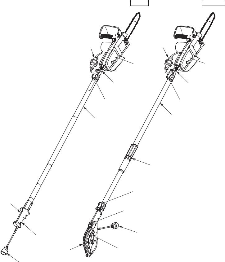
APPLICATIONS
As a pole saw:
•Pruning trees
NO ASSEMBLY TOOLS REQUIRED
Throttle
Lockout


 Throttle
Control
Handle
Handle
Power Cord
RM1025P
Power |
Power |
Receptacle |
Receptacle |
|
Mounting |
|
Bracket |
|
Inner Pole |
|
Clamping Lever |
Outer Pole
Coupler
Clamping Lever
Throttle Lockout
Power Cord
Throttle
Control
RM1025SPS
Mounting
Bracket
Inner Pole
Clamping Lever
Outer Pole
10
ESSENTIAL TERMS AND DEFINITIONS
•CHAIN SAW - A tool designed to cut wood with a saw chain. A chain saw is an integrated unit comprised of a motor, saw chain, guide bar, and handles that are designed to be held by two hands during operation.
•CHAIN SAW POWERHEAD - A chain saw without the saw chain and guide bar.
•DRIVE SPROCKET - A toothed wheel that drives the saw chain.
•FRONT HANDLE - A support handle located toward the front of the chain saw.
•REAR HANDLE - A support handle located toward the rear of the chain saw.
•FRONT HAND GUARD - A structural barrier between the front handle and the guide bar. The front hand guard helps protect the operator’s left hand if it slips off the front handle while the unit is running.
•REAR HAND GUARD - A structural barrier below the rear handle. The rear hand guard helps protect the operator’s right hand if the saw chain breaks or disengages from the guide bar during operation.
•GUIDE BAR - A solid railed structure that supports and guides the saw chain.
•GUIDE BAR TIP - The tip or end of the guide bar.
•REDUCED-KICKBACK GUIDE BAR - A guide bar that has been demonstrated to reduce kickback significantly.
•SAW CHAIN - A loop of chain with teeth designed to cut wood, which is driven by the motor and is supported by the guide bar. The saw chain is composed of drive links, cutters and side links, held together by rivets.
•LOW-KICKBACK SAW CHAIN - A saw chain that complies with the kickback performance requirements of ANSI/OPEI B175.1-2012 when tested on a representative sample of chain saws. Low-kickback saw chain significantly reduces the chance of kickback and the intensity of kickback, due to specially designed depth gauges and guard links.
•REPLACEMENT SAW CHAIN - A saw chain that complies with the kickback performance requirements of ANSI/OPEI B175.1-2012 when tested with specific chain saws. It may not meet the ANSI/OPEI performance standards when used with other chain saws.
•SPIKED BUMPER - The pointed tooth (or teeth), at the front of the chain saw, used during felling and bucking to help pivot the saw and maintain a stable position while cutting.
•CHAIN CATCHER - A device designed to intercept a whipping chain. The chain catcher reduces the chance of injury if the saw chain breaks or disengages from the guide bar during operation.
•OILER CONTROL - A system for oiling the saw chain and guide bar.
•SWITCH - A device that, when operated, will complete or interrupt an electrical power circuit to the motor.
•SWITCH LINKAGE - A mechanism that transfers motion from the trigger (throttle control) to the switch.
•TRIGGER (THROTTLE CONTROL) - A device that, when operated in conjunction with the switch lockout (throttle lockout), turns the motor on. Releasing the trigger (throttle control) immediately turns the motor off. The saw chain will then coast to a stop.
•SWITCH LOCKOUT (THROTTLE LOCKOUT) - A device that prevents the unit from starting accidentally. The trigger (throttle control) cannot be squeezed unless the switch lockout (throttle lockout) is manually engaged.
•OUTER POLE - A rigid tube that houses and retains the inner pole.
•INNER POLE - A moveable rigid tube inside the outer pole. Moving the inner pole adjusts the overall length of the pole. The saw attaches to a mounting bracket on the inner pole.
•CLAMPING LEVER - A device that allows the inner pole to move freely when unlocked and holds the inner pole in place when locked.
•KICKBACK - A sudden backward and/or upward motion of the guide bar and saw chain. Kickback can occur if the upper portion of the guide bar tip touches an object while the saw chain is spinning (rotational kickback). Kickback can also occur if the wood closes in and pinches the saw chain inside the cut (linear kickback).
•ROTATIONAL KICKBACK - A sudden backward and upward motion of the guide bar and saw chain. Rotational kickback can occur if the upper portion of the guide bar tip touches an object while the saw chain is spinning. The guide bar and saw chain are then kicked up and back toward the operator in a lightning-fast reverse reaction.
•LINEAR KICKBACK (PINCH KICKBACK) - A sudden backward motion of the guide bar and saw chain. Linear (pinch) kickback can occur if the wood closes in and pinches the saw chain inside a cut. The saw is then sent straight back toward the operator.
•NORMAL CUTTING POSITION - The positions assumed while making bucking and felling cuts.
•FELLING - The process of cutting down a tree.
•NOTCHED UNDERCUT - The first cutting procedure in the tree felling process. A notch is cut on one side of the tree to direct its fall.
•FELLING BACK CUT - The final cut in the tree felling process. The felling back cut is made on the opposite side of the tree from the notched undercut.
•BUCKING - The process of cutting a felled tree or log into lengths.
•LIMBING - The process of removing branches from a fallen tree.
•PRUNING - The process of cutting limbs from a living tree.
11

SPECIFICATIONS*
Motor Type . . . . . . . . . . . . . . . . . . . . . . . . . . . . . . . . . . . . . . . . . . . . . . . . . . . . . . . . . . . . . . . . . . . . . . . . . . . . . . . . . . . . . . . . . . . Electric, Corded Motor Voltage . . . . . . . . . . . . . . . . . . . . . . . . . . . . . . . . . . . . . . . . . . . . . . . . . . . . . . . . . . . . . . . . . . . . . . . . . . . . . . . . . . . . . . . . . . . . . . . 120 VAC Motor Amperage . . . . . . . . . . . . . . . . . . . . . . . . . . . . . . . . . . . . . . . . . . . . . . . . . . . . . . . . . . . . . . . . . . . . . . . . . . . . . . . . . . . . . . . . . . . . . 8 Amps Lubrication. . . . . . . . . . . . . . . . . . . . . . . . . . . . . . . . . . . . . . . . . . . . . . . . . . . . . . . . . . . . . . . . . . . . . . . . . . . . . . . . . . . . . . . . . . Bar and Chain Oil Chain Oil Reservoir Capacity . . . . . . . . . . . . . . . . . . . . . . . . . . . . . . . . . . . . . . . . . . . . . . . . . . . . . . . . . . . . . . . . . . . . . . . . . . . . . . 1.5 oz. (44 mL) Approximate Unit Weight (chain saw only - without chain oil) . . . . . . . . . . . . . . . . . . . . . . . . . . . . . . . . . . . . . . . . . . . . . . . 5 - 6 lbs. (2.3 - 2.7 kg) Approximate Unit Weight (RM1025P - without chain oil) . . . . . . . . . . . . . . . . . . . . . . . . . . . . . . . . . . . . . . . . . . . . . . . . 8.5 - 9.5 lbs. (3.9 - 4.3 kg) Approximate Unit Weight (RM1025SPS - without chain oil) . . . . . . . . . . . . . . . . . . . . . . . . . . . . . . . . . . . . . . . . . . . . . . . . 9 - 10 lbs. (4.1 - 4.5 kg) Guide Bar Length. . . . . . . . . . . . . . . . . . . . . . . . . . . . . . . . . . . . . . . . . . . . . . . . . . . . . . . . . . . . . . . . . . . . . . . . . . . . . . . . . . . . . . . 10 in. (25.4 cm) Saw Chain Pitch . . . . . . . . . . . . . . . . . . . . . . . . . . . . . . . . . . . . . . . . . . . . . . . . . . . . . . . . . . . . . . . . . . . . . . . . . . . . . . . . . . . . . . . 3/8 in. (9.5 mm) Saw Chain Gauge . . . . . . . . . . . . . . . . . . . . . . . . . . . . . . . . . . . . . . . . . . . . . . . . . . . . . . . . . . . . . . . . . . . . . . . . . . . . . . . . . . . . 0.050 in. (1.3 mm)
* All specifications are based on the latest product information available at the time of printing. We reserve the right to make changes at any time without notice.
REPLACEMENT PARTS
Please contact the Customer Support Department to order replacement parts.
Part # |
Description |
713-04088. . . . . . . . . . . . . . . . . . . . . . . . . . . . . . . . . . . . . . . . . . . . . . . . . Saw Chain (10 in. / 25.4 cm) 795-00112. . . . . . . . . . . . . . . . . . . . . . . . . . . . . . . . . . . . . . . . . . . . . . . . . Guide Bar (10 in. / 25.4 cm) 712-04232. . . . . . . . . . . . . . . . . . . . . . . . . . . . . . . . . . . . . . . . . . . . . . . . . Bar-Retaining Nuts
12

ASSEMBLY
WARNING: To prevent serious injury, never assemble, disassemble or adjust the unit while it is running. Always disconnect the unit from the power source to prevent the unit from starting accidentally. Always allow the unit to cool before assembling, disassembling or adjusting the unit.
ASSEMBLING THE POLE (RM1025SPS)
1.Unfold the pole and align the two ends. Do not twist or pinch the exposed wires (Fig. 1).
2.Align the tab on one end of the coupler with the slot on the other end (Fig. 1).
3.Push the two ends of the coupler firmly together until the tab locks into the slot with an audible snap.
NOTE: Once assembled, the pole cannot be disassembled.
ASSEMBLING AND DISASSEMBLING THE POLE SAW
This unit can be used as a chain saw or as a pole saw. Connect the chain saw to the pole for most pruning operations. Disconnect the unit from the pole for other operations, such as felling, limbing and bucking trees.
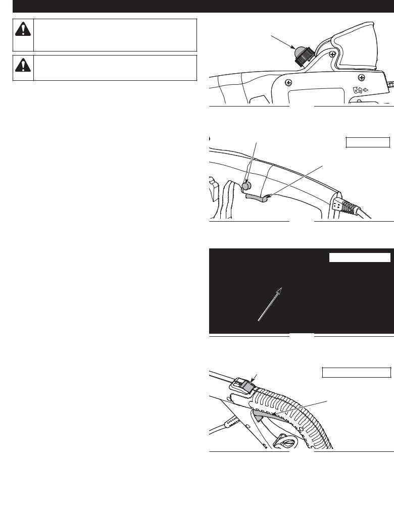
Installing the Chain Saw on the Pole
1.Set the chain saw and pole on a flat, level surface.
2.Press and hold the throttle lockout (Fig. 7). Then, squeeze and hold the throttle control (Fig. 7). Refer to Starting and Stopping.
3.Insert the bracket into the open area between the rear handle and rear hand guard (Fig. 2). The bracket should fit securely in place and hold the throttle control in the squeezed position.
4.Slide the bracket cover onto the bolt (Fig. 2).
5.Slide the washer onto the bolt (Fig. 2).
6.Thread the knob onto the bolt (Fig. 2). Turn the knob clockwise to tighten the bracket cover securely to the bracket.
7.Connect the power cord on the chain saw to the power receptacle on the pole (Fig. 3).
Removing the Chain Saw from the Pole
1.Set the unit on a flat, level surface.
2.Disconnect the power cord on the chain saw from the power receptacle on the pole (Fig. 3).
3.Turn the knob counterclockwise to remove the knob from the bolt (Fig. 2).
4.Remove the washer from the bolt (Fig. 2).
5.Remove the bracket cover from the bolt (Fig. 2).
6.Separate the chain saw from the bracket (Fig. 2).
ADJUSTING THE POLE LENGTH
To help maintain proper balance, only extend the pole to the minimum length required to reach the limb being cut.
1.Flip the clamping lever up (Fig. 4).
2.Slide the inner pole to the desired length (Fig. 4).
3.Flip the clamping lever down to lock the inner pole in place (Fig. 4).
NOTE: The RM1025SPS model has two moveable inner pole sections and two clamping levers.
Wires
Slot
Fig. 1
Bolt
Bracket
Fig. 2
Power Receptacle
Power Cord
Fig. 3
Clamping Lever
Tab
Coupler
Bracket
Cover
Washer
Knob
Inner Pole
Fig. 4
13

ADDING BAR AND CHAIN OIL: INITIAL USE
This unit comes from the factory with the chain oil reservoir empty. Fill the chain oil reservoir with bar and chain oil before starting or using the unit. Refer to Adding Bar and Chain Oil instructions in the
Maintenance section.
ADJUSTING THE CHAIN TENSION: INITIAL USE
The saw chain must be properly tensioned before attempting to start or operate the unit. The saw chain may also require additional tensioning as the saw chain heats up during operation. Refer to
Adjusting the Chain Tension instructions in the Maintenance section.
CONNECTING AND DISCONNECTING THE POWER SOURCE
WARNING: Make sure the throttle control is released before connecting or disconnecting the power source. Refer to the Starting and Stopping section.
Connecting the Unit to the Power Source (RM1025P or as a Chain Saw)
1.Make a loose knot with the power cord and an appropriate extension cord. Refer to Fig. B in the Safety section.
2.Plug the power cord into the extension cord.
3.Plug the extension cord into an appropriate power outlet.
Connecting the Unit to the Power Source (RM1025SPS)
1.Plug the power cord into the extension cord.
2.Make a narrow loop in the extension cord (Fig. 5).
3.Push the loop through the hole in the handle (Fig. 5).
4.Position the loop onto the cord hook (Fig. 5). Gently pull the loop to secure the cord in place.
5.Plug the extension cord into an appropriate power outlet.
Disconnecting the Unit from the Power Source (RM1025P or as a Chain Saw)
1.Unplug the extension cord from the power outlet.
2.Unplug the power cord from the extension cord.
3.Untie the knot in the power cord and extension cord.
Disconnecting the Unit from the Power Source (RM1025SPS)
1.Unplug the extension cord from the power outlet.
2.Unplug the power cord from the extension cord.
3.Remove the looped cord from the cord hook and hole in the handle (Fig. 5).
Handle |
Power Cord |
|
Cord Hook |
Extension Cord |
Fig. 5
14
STARTING AND STOPPING
WARNING: Never operate the unit without the guide bar and saw chain properly installed. Make sure the bar-retaining nuts are tight and the guide bar cover is securely assembled. Make sure the saw chain is properly tensioned.
WARNING: The saw chain will spin after the unit starts. Keep hands and feet clear of the saw chain and do not allow the saw chain to contact any object(s).
BEFORE STARTING THE UNIT
1.Fill the chain oil reservoir with bar and chain oil. Refer to Adding Bar and Chain Oil in the Maintenance section.
2.Connect the power cord to an appropriate extension cord. Connect the extension cord to an appropriate power outlet. Refer to Connecting and Disconnecting the Power Source.
3.Press the chain oil bulb to oil the guide bar and saw chain (Fig. 6).
STARTING INSTRUCTIONS
To help prevent the motor from starting accidentally, the throttle lockout and throttle control must both be engaged to start the unit.
1.Press and hold the throttle lockout (Fig. 7 - 9).
2.Continue to hold the throttle lockout. Squeeze and hold the throttle control to start the unit (Fig. 7 - 9).
3.Release the throttle lockout, but continue to squeeze the throttle control.
STOPPING INSTRUCTIONS
1.Release the throttle control and wait for all moving parts to come to a complete stop (Fig. 7 - 9).
NOTE: Upon release of the throttle control, the throttle lockout will reset to the locked position.
Chain Oil Bulb
Fig. 6
Throttle Lockout
Chain Saw
Throttle Control
Fig. 7
Pole Saw - RM1025P
Throttle Lockout |
|
Throttle Control |
|
Fig. 8 |
|
|
Throttle Lockout |
Pole Saw - RM1025SPS |
|
|
|
|
|
Throttle Control |
Fig. 9
15

OPERATION
WARNING: Do not expose power tools to rain or wet conditions.
WARNING: Always check the chain tension and adjust as necessary before beginning operation. Refer to Adjusting the Chain Tension in the Maintenance section.
WARNING: Make sure the chain oil reservoir is full before operation. Check the oil level constantly so that it does not drop below half full. Press the chain oil bulb at least once before each cut. The saw chain must be continuously coated with oil to function properly.
WARNING: Always wear appropriate eye, hearing, hand, foot and body protection to reduce the risk of injury when operating this unit. Wear head protection. Use a full face shield when needed. Refer to the Safety section for appropriate safety equipment information.
WARNING: Do not use a pole saw to fell a tree. Do not use a pole saw to limb or buck a fallen tree. Use a chain saw for these applications.
TIPS FOR BEST RESULTS
•Follow all safety instructions. Refer to the Safety section.
•Only cut wood and materials made of wood. Do not attempt to cut sheet metal, plastics, masonry or any other non-wood materials.
•Practice cutting a few small logs before beginning a major cutting operation. First-time users should practice cutting logs on a sawhorse or cradle before undertaking other operations.
•Do not attempt to cut trees or logs with diameters larger than 6 in. (15.2 cm).
PREPARING THE WORK AREA
•Clear the area of children, bystanders and pets; keep them outside a 50-foot (15 m) radius, at a minimum. Even then, they are still at risk from thrown objects. Encourage bystanders to wear eye protection. If you are approached, stop the unit immediately. When felling, the safe distance is at least twice the height of the tallest tree in the work area. When bucking, keep workers at least 15 feet (4.6 m) apart.
•Keep the work area clean. Cluttered areas invite injuries. Do not start cutting until the work area is clear and free from obstructions. Make sure there is secure footing and a planned retreat path from falling trees or branches.
•Do not cut near electrical cables or power lines. Keep at least 50 feet (15 m) away from all power lines.
•Use the unit only in daylight or good artificial light.
16

HOLDING THE UNIT
WARNING: Always use the hand placements specified below whether the operator is left-handed or right-handed. This will help keep the operator slightly to the left of the unit and out of the direct line of the saw chain if kickback occurs (Fig. 13 and Fig. 14). Always keep all body parts to the left of the chain line.
•Always grip the unit firmly with both hands when the unit is running.
•Firmly encircle the handles and/or pole with the thumbs and fingers (Fig. 10). This will help reduce the chance of losing control of the unit if kickback occurs. Any grip with thumbs and fingers on the same side of the handles and/or pole is dangerous (Fig. 11).
•Stand in a stable position with feet apart and firmly planted.
As a Chain Saw
•Hold the front handle with the left hand. Keep the left arm straight to help withstand potential kickback.
•Hold the rear handle with the right hand. Keep the right arm slightly bent.
•Do not cut above shoulder height. Do not overreach.
As a Pole Saw
•Hold the pole with the left hand. Keep the left arm straight. Always hold the pole in the grip area (Fig. 12).
•Hold the handle with the right hand. Keep the right arm slightly bent.
•Hold the unit at waist level (Fig. 12).
•Do not extend arms above shoulder height. Do not overreach.
CUTTING PROCEDURE BASICS
1.Start the unit. Refer to Starting Instructions in the Starting and Stopping section.
2.Accelerate the unit to full speed before cutting.
3.Press the unit against the wood and maintain a firm, steady pressure through most of the cut. Do not put pressure on the unit at the end of the cut.
4.Maintain a steady speed throughout the cut. Keep the unit running through the entire cut.
5.Do not try to force the saw through the wood. Allow the saw chain to do the cutting. Exert only light pressure. Forcing the cut could result in damage to the unit or personal injury.
6.Release the throttle control as soon as the cut is completed. Allow the saw chain to come to a complete stop. The saw chain, guide bar and motor may experience unnecessary wear if the unit is run without a cutting load.
Correct Grip
Thumbs Below the Handles
Fig. 10
Incorrect Grip |
Thumb |
|
|
|
Above the |
|
Handle |
Fig. 11
Waist Level
Grip Area
Fig. 12
Chain Line
Correct Stance
Fig. 13
17
FELLING: SAFETY
Felling is the process of cutting down a tree. Follow these safety precautions to reduce the risk of serious injury, property damage and damage to electrical lines:
•Do not fell trees with an extreme lean. Do not fell trees with rotten limbs, loose bark or hollow trunks. Have these trees pushed or dragged down with heavy equipment.
•Do not cut trees near buildings or electrical lines. Leave these operations for professionals. If a felled tree does contact an electrical line, notify the utility company immediately.
•Check the tree for damaged or dead branches that could fall and cause serious injury.
•Remove dirt, stones, loose bark, nails, wire and other obstructions from the portion of the tree that will be cut.
•When bucking and felling operations are performed by two or more persons in the same general area, they should be separated from each other by a distance of at least twice the height of the tree to be felled.
•Consider the force and direction of the wind. Consider the lean and balance of the tree. Consider the location of large branches. All of these factors influence the direction that the tree will fall. Do not try to fell a tree in a direction other than its natural fall line.
•Do not fell trees during periods of precipitation or high winds.
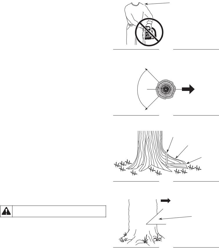
•Determine a safe and expedient escape route. Clear the area around the tree and make sure there are no obstructions blocking the escape route. Establish a 90º corridor of escape, approximately 135º from the line of fall (Fig. 15).
•Stay uphill from the tree; it will most likely roll or slide after it falls.
FELLING: PROCEDURE
Small trees, up to 6 - 7 inches (15 - 18 cm) in diameter, are usually felled in a single cut. Larger trees require a sequence of two cutting operations: a notched undercut followed by a felling back cut. It may also be necessary to remove buttress roots.
Step 1: Removing Buttress Roots
Buttress roots are large roots that extend above the ground and help support the tree. If the tree has large buttress roots that might impede the felling process, follow these steps to remove them:
1.Make a horizonal cut into the buttress root (Fig. 16). To prevent the guide bar from being pinched by the weight of the wood, always make this cut first.
2.Make a vertical cut into the buttress root (Fig. 16).
3.Remove the loose section from the work area.
Step 2: Making the Notched Undercut
WARNING: Never walk in front of a tree with a notched undercut.
This cut determines which direction the tree will fall. Always make this cut on the side of the tree facing the direction where the tree should fall. Make the cut at 90º to the line of fall.
1.Make a horizontal cut into the trunk of the tree (Fig. 17). The cut should be about 1/3 the diameter of the tree and close to the ground. To prevent the guide bar from being pinched by the weight of the wood, always make this cut first.
2.Make a 45º cut into the trunk of the tree, above the first cut (Fig. 17). Continue cutting until the two cuts meet.
3.Remove the loose section from the work area.
Chain Line
Incorrect Stance
Fig. 14
Path of Safe
Retreat 90°
1/3 Diameter
135º From Planned
Line of Fall
Planned
Line of Fall
135º From Planned
Line of Fall
Fig. 15
Second Cut
Buttress Root
First Cut
Fig. 16
Direction of Fall
Second Cut
Notched
Undercut
First Cut
Fig. 17
18

Step 3: Making the Felling Back Cut
WARNING: Always recheck the area for bystanders, animals and obstacles before making the felling back cut.
This cut fells the tree.
1.Make a horizontal cut into the opposite side of the tree from the notched undercut (Fig. 18). Make the cut approximately 2 inches (5 cm) above the bottom of the notched undercut (Fig. 18).
2.As the cut gets close to the notched undercut, only a thin band of wood will support the tree. This band of wood is referred to as the hinge (Fig. 18). The hinge helps control the fall of the tree. Leave approximately 2 inches (5 cm) of hinge in place. Do not cut through the hinge. Cutting through the hinge could cause the tree to fall in any direction.
3.Periodically glance up during the felling back cut to see if the tree is going to fall in the correct direction. If there is a chance that the tree might not fall in the desired direction, or if the tree might rock back and bind the chain saw, remove the guide bar from the cut, stop the unit and use wedges to open the cut and direct the fall (Fig. 19). Only use soft plastic or wooden wedges. Drive the wedges into the cut slowly. Once the wedges are in place and the cut is held open, either carefully reinsert the guide bar and continue the cut or slowly drive the wedges in further to push the tree over.
4.As the hinge gets smaller, the tree should begin to fall. When the tree begins to fall, remove the chain saw from the cut, stop the motor and set the unit down immediately. Promptly exit the area along the retreat path, but keep watching the tree as it falls.
DANGER: If the tree starts to fall in the wrong direction and binds the chain saw, leave the unit and evacuate the area immediately! Do not try to save the chain saw!
WARNING: Stay clear of spring poles when operating the unit. Spring poles are branches, logs, roots or saplings that are bent under tension by other wood (Fig. 20). When the tension is released, spring poles can strike the operator, causing serious injury and potentially knocking the chain saw into the operator’s body. Use extreme caution when cutting spring poles or when releasing the cause of tension.
Felling
Back Cut 2 inches (5 cm)
Hinge
2 inches (5 cm)
Fig. 18
Wedge
Fig. 19
Spring Pole
Fig. 20
LIMBING
Limbing is the process of removing branches from a fallen tree.
1. Leave the larger support limbs under the tree for last (Fig. 21). These will keep the tree off the ground during the limbing process.
2. Cut one limb at a time. Stand on the opposite side of the tree from the limb (Fig. 21). Keep the trunk between the operator and the chain saw. To avoid binding the chain saw, branches under tension should be cut from the bottom up.
3. Remove the cut limbs from the work area.
Support Limb
Fig. 21
19
BUCKING: SAFETY
Bucking is the process of cutting a fallen tree into logs of desired lengths. Follow these safety precautions to reduce the risk of serious injury:
•Clear the area of objects or obstructions that could contact the guide bar and result in kickback.
•When bucking on a slope, always stand on the uphill side of the fallen tree.
•If possible, the end of the tree to be cut should be raised off of the ground. A saw horse is ideal for this purpose. If a saw horse is not available, use other logs or any remaining limb stumps. Make sure the tree if firmly supported.
•Do not let the saw chain contact the ground or saw horse.
•Cut one log at a time. Release the throttle control and allow the saw chain to come to a complete stop before moving on to the next log.
•Keep feet and all other body parts clear of falling logs.
DANGER: Use extreme caution when cutting a fallen tree that is still attached to the root structure. When the trunk is separated from the roots, the stump has a high potential for rocking back into the hole created by the roots. This can result in serious injury or death. Never stand in the hole left by the roots. Never allow others to stand near the root structure.
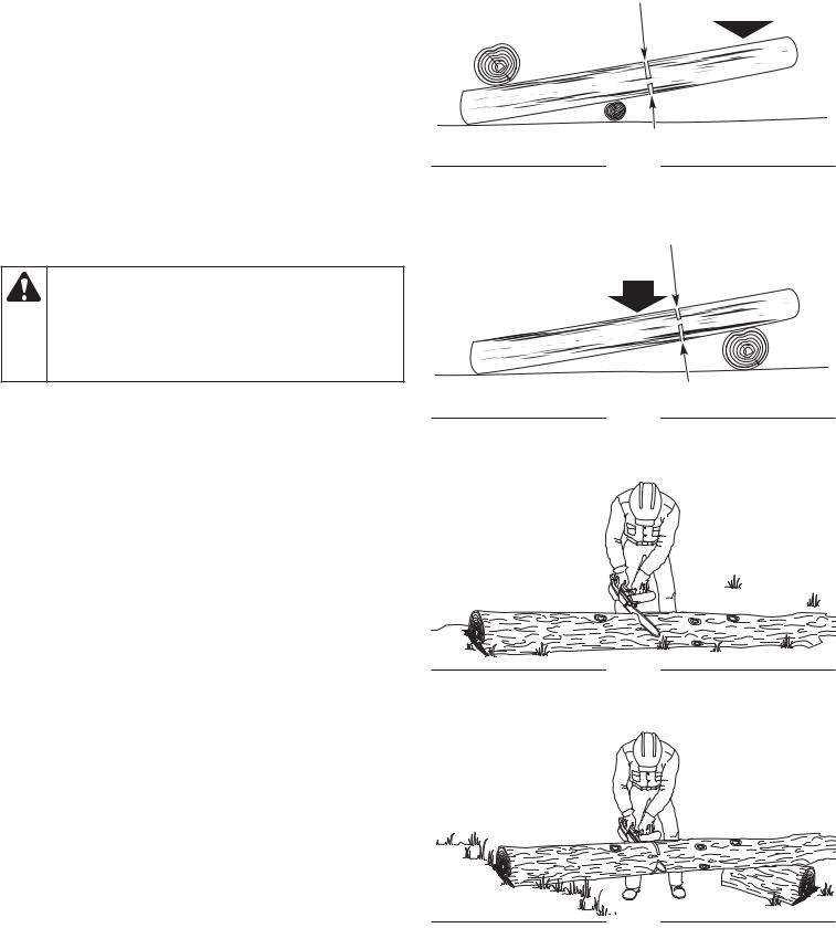
BUCKING: PROCEDURE
Cutting Logs Under Stress
When logs are supported on one or both ends, the wood tends to bend during the cutting process. This can cause the chain saw to become pinched between the two sides. Pay extra attention.
1.Make the first cut approximately 1/3 the diameter of the log. Do not cut deeper than 1/3.
•If the log is supported on one end (Fig. 22), make the first cut from below (underbucking). Refer to Underbucking.
•If the log is supported on two ends (Fig. 23), make the first cut from above (overbucking). Refer to Overbucking.
2.Make the second cut from the opposite side until the two cuts meet. If the diameter of the wood is large enough, insert soft plastic or wooden wedges to hold the cut open and prevent pinching (Fig. 26). Take care not to touch the wedges with the saw chain.
Cutting Fully-Supported Logs
When logs are supported along the entire length, extra care should be taken to make sure the saw chain does not contact the ground or other support structure (Fig. 24).
1.Cut through the log as much as possible, without cutting into the ground or support structure. Cut from above (overbucking). Refer to Overbucking.
2.Roll the log over and finish cutting through the log from above (overbucking).
Log Supported
on One End
Log Supported
Two Ends
Overbucking
Underbucking
Second Cut |
Load |
|
|
|
|
|
|
First Cut (1/3 Diameter)
Fig. 22
First Cut (1/3 Diameter)
Load
Second Cut
Fig. 23
Fig. 24
Fig. 25
20
Overbucking
1.Begin cutting from above, with the bottom of the saw chain against the top of the log (Fig. 24).
2.Exert light, downward pressure. The saw will tend to pull away from the operator. Be prepared and hold the saw firmly to maintain control.
Underbucking
1.Begin cutting from below, with the top of the saw chain against the bottom of the log (Fig. 25).
2.Exert light, upward pressure. The saw will tend to push toward the operator. Be prepared and hold the saw firmly to maintain control.
PRUNING
WARNING: Do not cut above shoulder height with a chain saw. Use a pole saw to cut limbs above shoulder height or hire a professional. Do not operate the unit in a tree or on a ladder unless specifically trained to do so.
WARNING: Falling branches can cause serious injury. Always wear appropriate head protection. Plan an escape route away from falling limbs. Do not position any body parts directly below the limb when cutting.
Pruning is the process of cutting limbs from a living tree.
1.Make the first cut approximately 6 inches (15 cm) from the tree trunk. Cut upward, from the underside of the limb. Use the top of the guide bar to make this cut. Cut a third of the way through the diameter of the limb (Fig. 27).
2.Make the second cut 2 - 4 inches (5 - 10 cm) farther out on the limb. Cut downward, from the top of the limb. Use the bottom of the guide bar to make this cut. Cut completely through the limb (Fig. 27).
3.Make the third cut as close to the tree trunk as possible. Cut upward, from the underside of the limb stub. Use the top of the guide bar to make this cut. Cut a third of the way through the diameter of the limb (Fig. 27).
4.Make the fourth cut directly above the third cut. Cut downward, from the top of the limb stub. Use the bottom of the guide bar to make this cut. Cut completely through the limb stub to meet the third cut (Fig. 27). This will remove the limb stub.
Wedge
Fig. 26
Second Cut
Fourth Cut
First Cut
Third Cut
Fig. 27
21

MAINTENANCE
WARNING: To prevent serious injury, never perform maintenance or repairs while the unit is running. Always disconnect the unit from the power source to prevent the unit from starting accidentally. Always allow the unit to cool before servicing or repairing the unit.
MAINTENANCE SCHEDULE
Perform these required maintenance procedures at the frequency stated in the table. These procedures should also be a part of any seasonal tune-up.
All service, other than the maintenance procedures described in this manual, should be performed by an authorized service dealer.
NOTE: Some maintenance procedures may require special tools or skills. If you are unsure about these procedures, take the unit to an MTD authorized service dealer.
CUSTOMER RESPONSIBILITY
FREQUENCY |
MAINTENANCE REQUIRED |
Before each |
• Check for loose screws, nuts or bolts |
use |
(tighten as needed) |
|
• Check for damaged or worn parts* |
|
• Check the saw chain sharpness. Refer to |
|
Sharpening the Saw Chain. |
|
• Check the chain tension (adjust as needed). |
|
Refer to Adjusting the Chain Tension. |
|
• Fill the chain oil reservoir (refill frequently). |
|
Refer to Adding Bar and Chain Oil. |
|
|
After each use |
• Clean the unit and inspect decals. Refer to |
|
Cleaning in the Cleaning and Storage |
|
section. |
|
|
Every 10 hours |
• Clean the guide bar groove and oil |
|
passages. |
|
|
* If maintenance or replacement is required, have the unit serviced by an MTD authorized service dealer.
22

ADDING BAR AND CHAIN OIL
DANGER: Failure to fill the chain oil reservoir will cause irreparable damage to the unit. Make sure the chain oil reservoir is always filled. Always use bar and chain oil.
WARNING: Check the chain oil level frequently so that it does not drop below half full.
The guide bar and saw chain require lubrication to minimize friction. Never starve the guide bar and chain of lubricating oil. Running the unit without enough oil will decrease cutting efficiency, shorten the life of the saw chain, cause rapid dulling of the saw chain and excessive wear to the guide bar from overheating. An insufficient amount of lubricating oil is evidenced by smoke, guide bar discoloration or pitch build-up.
Only use bar and chain oil that is formulated to perform over a wide range of temperatures with no diluting required in the chain oil reservoir. Do not use motor oil or any other petroleum-based oil. Do not use dirty, used or contaminated oil. Damage may occur to the guide bar or saw chain. Dispose of old oil according to federal, state and local regulations.
Checking the Chain Oil Level
1.Set the unit on a flat, level surface.
2.Look into the chain oil level window; use a flashlight if necessary. The oil level should fill the window at least halfway (Fig. 28). If the oil level is too low, add bar and chain oil. Refer to
Filling the Chain Oil Reservoir.
Filling the Chain Oil Reservoir
1.Set the unit on a flat, level surface.
2.To prevent debris from entering the chain oil reservoir, use a damp cloth to clean the chain oil reservoir cap and surrounding area.
3.Unscrew the chain oil reservoir cap (Fig. 29).
4.Carefully pour the oil into the chain oil reservoir. DO NOT overfill.
5.Reinstall the chain oil reservoir cap. Tighten the cap firmly.
6.Wipe up any oil that may have spilled.
ADJUSTING THE CHAIN TENSION
CAUTION: The guide bar, saw chain, and saw bearings will wear more rapidly if the saw chain is not properly tensioned. Maintaining proper chain tension will improve cutting performance and prolong the life of the saw chain.
WARNING: To prevent serious injury, never touch the saw chain or adjust the chain tension while the unit is running. Disconnect the unit from the power source to prevent the unit from starting accidentally.
WARNING: The saw chain is very sharp. Always wear heavy-duty protective gloves when handling or performing maintenance on the saw chain.
Check the chain tension before and during operation. Adjust the chain tension whenever the flats on the saw chain hang out of the bar groove (Fig. 30).
NOTE: A new saw chain tends to stretch and will need readjustment after as few as five (5) cuts. This is normal during the break-in period. The interval between future adjustments will lengthen quickly.
Chain Oil
Level Window
Fig. 28
Chain Oil
Reservoir Cap
Chain Oil
Reservoir
Fig. 29
Flats |
Drive Links |
Guide Bar |
|
|
|
|
|
|
Fig. 30 |
|
|
23

1.Use a 7/16 inch (11 mm) wrench to slightly loosen the barretaining nuts (Fig. 31). DO NOT remove the bar-retaining nuts.
2.Hold the guide bar tip up and use a flat-head screwdriver to turn the chain-tensioning screw (Fig. 32).
•Turn the chain-tensioning screw clockwise to tighten the saw chain.
•Turn the chain-tensioning screw counterclockwise to loosen the saw chain.
The desired chain tension depends upon the temperature of the saw chain (Fig. 33).
•Cold Chain Tensioning - The saw chain should fit snuggly against the underside of the guide bar. There should be no sag (Fig. 33).
•Warm Chain Tensioning - The saw chain will expand as it heats up during operation. The drive links should hang approximately 1/16 inch (1.3 mm) out of the guide bar groove (Fig. 33).
3.Hold the guide bar tip up and move the saw chain back and forth along the guide bar (Fig. 34). Make sure the saw chain moves freely and is in proper mesh with the sprocket. If the saw chain does not move easily, slowly turn the chain-tensioning screw counterclockwise to loosen the saw chain.
4.Hold the guide bar tip up and securely tighten the bar-retaining nuts.
CAUTION: If the saw chain was tensioned while warm, it may become too tight when cooled. Loosen the chain tension after operation and check the chain tension before the next use.
Bar-Retaining Nuts
Guide Bar Tip 


Fig. 31

 Chain-Tensioning
Screw
Fig. 32
Correct Cold Tension |
Too Loose |
Correct Warm Tension
Fig. 33
Fig. 34
24

REMOVING AND INSTALLING THE GUIDE BAR AND SAW CHAIN
WARNING: The saw chain is very sharp. Always wear heavy-duty protective gloves when handling or performing maintenance on the saw chain.
The guide bar and saw chain need to be removed when certain maintenance procedures are performed, such as when rotating the guide bar. When replacing old guide bars and saw chains with new parts, always use the manufacturer’s specified replacement parts. Refer to Replacing the Guide Bar and Saw Chain.
Removing the Guide Bar and Saw Chain
1.Use a Phillips screwdriver to remove the four (4) screws that hold the bar cover in place (Fig. 35).
2.Remove the bar cover.
3.Use a 7/16 inch (11 mm) wrench to slightly loosen the barretaining nuts (Fig. 35). DO NOT remove the bar-retaining nuts.
4.Loosen the saw chain. Refer to Adjusting the Chain Tension.
5.Remove the saw chain from the guide bar.
6.Remove the guide bar from the guide bar bolts (Fig. 36).
Installing the Guide Bar and Saw Chain
1.Use a flat-head screwdriver to turn the chain-tensioning screw counterclockwise (Fig. 32) until the chain-tensioning pin is at the far left of the mounting surface (Fig. 37).
2.Align the slot in the guide bar with the guide bar bolts (Fig. 36). Insert the guide bar between the sprocket support and mounting surface (Fig. 36). Slide the guide bar completely onto the guide bar bolts (Fig. 36).
3.Make sure the chain-tensioning pin is in the pin hole on the guide bar (Fig. 37). If necessary, turn the chain-tensioning screw to move the chain-tensioning pin.
4.Tighten the bar-retaining nuts hand tight (Fig. 35).
5.Set the saw chain on a clean, flat surface and straighten out any kinks.
6.Loop the saw chain around the drive sprocket (Fig. 38). Make sure the flats on the saw chain are in the grooves on the drive sprocket. Make sure the cutters point in the correct direction of rotation (Fig. 38).
7.Fit the saw chain into the guide bar groove (Fig. 38).
8.Place the bar cover onto the saw housing (Fig. 35). Align the holes in the bar cover with the holes in the saw housing.
9.Insert the four (4) screws into the aligned holes. Tighten the screws securely.
10.Make sure the saw chain is still in the guide bar groove, then tighten the saw chain. Refer to Adjusting the Chain Tension.
11. Hold the guide bar tip up and securely tighten the bar-retaining nuts.
25
Screws (3)
Bar Cover
Screw (1) |
Saw Housing |
Fig. 35
Guide Bar Bolts
Bolts
Mounting Surface
Guide Bar


 Bar-Retaining
Nuts
Sprocket Support
Fig. 36
Pin Hole
Chain-Tensioning Pin
Fig. 37
Cutter
|
|
Saw |
|
Guide Bar |
Chain |
|
Flat |
|
|
Groove |
|
|
|
|
Drive |
|
Direction of |
Sprocket |
|
|
|
Rotation |
|
|
|
|
|
Fig. 38 |
|

MAINTAINING THE SAW CHAIN
For safe, efficient operation, the saw chain must be maintained properly.
The saw chain will wear with use, causing the chain to stretch. This is normal. When it is no longer possible to obtain a correct chain tension adjustment, the saw chain will need to be repaired by an authorized service dealer or replaced. Refer to Replacing the Guide Bar and Saw Chain.
Always keep the saw chain sharp. During operation, look for the following indicators of a dull saw chain:
•Wood chips are small and powdery.
•The saw chain must be forced through the wood.
•The saw chain cuts to one side.
If any of these conditions exist, sharpen or replace the saw chain. Refer to Sharpening the Saw Chain or Replacing the Guide Bar and Saw Chain.
NOTE: If you do not fully understand the sharpening procedure after reading the instructions, have the saw chain sharpened by an authorized service dealer or replace the saw chain.
SHARPENING THE SAW CHAIN
WARNING: The saw chain is very sharp. Always wear heavy-duty protective gloves when handling or performing maintenance on the saw chain.
WARNING: An improperly sharpened saw chain increases the chance of kickback. Failure to replace or properly maintain the saw chain can cause serious injury.
CAUTION: A dull or improperly sharpened saw chain can cause excessive motor speed during operation, which can result in severe motor damage.
If the saw chain was damaged by contacting hard objects, such as nails or stones, or was abraded by mud or sand on the wood, have an authorized service dealer sharpen the saw chain.
When sharpening the saw chain, file all cutters to the specified angles and measurements. Other angles or measurements can cause excessive wear to the guide bar and saw chain, cause the chain to dull quickly and increase the chance of kickback. Fast cutting can be obtained only when all cutters are uniform.
1.Tighten the chain tension so that the saw chain is taut and does not wobble. Refer to Adjusting the Chain Tension.
•Always file the saw chain at the midpoint of the guide bar.
2.Use a round file and file holder (tools not included) to sharpen the top plate and side plate of each cutter.
•Use a 5/32 inch (4 mm) diameter file.
•Keep the file level with the top plate of the cutter (Fig. 39). Do not let the file dip or rock. Use light, but firm pressure.
•File toward the front corner of the cutter (Fig. 40). Lift the file away from the cutter at the end of the forward stroke. Only file on the forward stroke.
•Apply a few firm strokes to each tooth. When filed correctly, the top plate will be at a 30º angle and the side plate will be at an 80º angle (Fig. 41). Using the correct file and file holder will automatically produce the correct angles.
•File all the left-hand cutters in one direction (Fig. 40). Then move to the other side of the saw chain and file all of the righthand cutters in the opposite direction (Fig. 40).
•Occasionally remove filings with a wire brush.
Depth Gauge Clearance
1/32 inch (0.6 mm)
Depth Gauge
Top Plate 
Side Plate
Fig. 39
Filing Angle
Left-Hand
Cutters
Right-Hand
Cutters
Fig. 40
Correct Filing Angles
Top Plate
80º
30º
Side Plate
Fig. 41
Depth Gauge Jointer
Flat File
Fig. 42
26

3.Use a depth gauge tool (not included) to measure the depth gauge clearance (Fig. 42) of each cutter. The depth gauge clearance must be maintained at 1/32 inch (0.6 mm). The depth gauge clearance determines the depth at which the cutter enters the wood during operation and the size of the wood chips produced. Too much clearance increases the chance of kickback. Too little clearance decreases the size of the wood chips, thus deceasing the ability to cut.
•Use a 0.025 inch (0.635 mm) depth gauge jointer and a flat file (tools not included) to lower the depth gauge to the correct clearance (Fig. 42).
•After lowering the depth gauge, use the flat file to restore the original rounded shape to the depth gauge (Fig. 43). Take care not to damage the cutting edges or nearby links.
MAINTAINING THE GUIDE BAR
1.Rotate the guide bar frequently, at regular intervals (for example, after every 5 hours of operation), to ensure even wear on the top and bottom of the guide bar. Refer to Removing and Installing the Guide Bar and Saw Chain.
2.Clean the guide bar groove and oil passages whenever the saw chain is removed, when the unit has been used heavily or when the saw chain appears dirty. Use a screwdriver, putty knife, wire brush or similar instrument to remove debris from the guide bar groove (Fig. 44). Use a small, soft wire to remove any debris from the chain oil discharge hole (Fig. 45).
NOTE: If the oil passages are clear, the saw chain will give off a spray of oil shortly after it begins to rotate during operation.
3.Frequently check the guide bar for damage (Fig. 46). Feathering and burring of the guide bar rails (the ridges on either side of the bar groove) is a normal process of guide bar wear. Such faults should be smoothed with a file as soon as they occur (Fig. 46). A guide bar with the following faults should be replaced:
•Wear inside the guide bar rails that permits the chain to lay sideways
•Bent guide bar
•Cracked or broken rails
•Spread rails
Refer to Replacing the Guide Bar and Saw Chain.
REPLACING THE GUIDE BAR AND SAW CHAIN
WARNING: Always use a low-kickback saw chain, which significantly reduces the danger of kickback. Lowkickback saw chain does not completely eliminate kickback. A low-kickback or “safety chain,” should never be regarded as total protection against injury.
When replacing the guide bar and saw chain, only use the replacement parts specified by the manufacturer or their equivalents. Refer to Replacement Parts. Use of any unauthorized parts or accessories could lead to serious injury to the operator or damage to the unit and will VOID the warranty.
Always use a replacement saw chain designated as “low-kickback” or a saw chain that meets the low-kickback performance requirements. A standard saw chain (a chain that does not have the kickback-reducing guard links) should only be used by an experienced professional chain saw operator.
Restore original rounded shape
Fig. 43
Oil Passage
Guide Bar Groove
Fig. 44
Chain Oil
Discharge Hole
Fig. 45
Flat File
Bur |
Uneven Wear |
Spread Rails |
Fig. 46
27

CLEANING AND STORAGE
CLEANING
WARNING: To prevent serious injury, never clean the unit while it is running. Always disconnect the unit from the power source to prevent the unit from starting accidentally. Always allow the unit to cool before cleaning the unit.
WARNING: To prevent serious injury, do not douse the unit with water. Do not submerge the unit in water or any other liquid. Do not use strong detergents. Household cleaners that contain aromatic oils such as pine and lemon, and solvents such as kerosene, can damage plastic.
1.Loosen the saw chain if the chain tension was adjusted during operation. The saw chain will contract as the unit cools, which could damage the unit if the chain is too tight.
2.Clean the unit with a damp cloth.
NOTE: When preparing the unit for long-term storage (30 days or more), remove the guide bar and saw chain. Carefully clean the guide bar cover, guide bar mounting surface and sprocket. Use a firm non-wire brush to clean the guide bar groove. Reassemble the unit.
3.Wipe off any moisture with a soft cloth.
4.Lightly coat the guide bar and saw chain with a corrosioninhibiting oil.
STORAGE
•Loosen the saw chain if the chain tension was adjusted during operation. The saw chain will contract as the unit cools, which could damage the unit if the chain is too tight.
•Allow the unit to cool.
•Thoroughly clean the unit and inspect it for any loose or damaged parts. Repair or replace damaged parts and tighten loose screws, nuts or bolts.
•Cover the guide bar and saw chain with the scabbard.
•Lock up the unit to prevent unauthorized use or damage.
•Store the unit in a dry, well-ventilated area.
•Store the unit out of the reach of children.
NOTE: It is normal for bar and chain oil to seep from the unit when not in use. Please take this into consideration when storing the unit.
28

TROUBLESHOOTING
PROBLEM |
SOLUTION |
|
|
THE MOTOR WILL NOT START
The extension cord is not securely connected to the unit or power source
The GFCI in the outlet has tripped (if used)
The breaker switch has tripped
The throttle lockout was not pressed
The unit is damaged
Make sure each plug is securely connected
Reset the GFCI
Reset the breaker switch in the home electrical panel
Press and hold the throttle lockout before squeezing the throttle control Refer to Service information
THE MOTOR LACKS POWER OR STALLS
The extension cord wire size is inadequate |
Use an extension cord with the necessary wire size. Refer to the |
|
wire size table in the Safety section. |
||
|
||
|
|
|
THE SAW CHAIN COMES OFF THE GUIDE BAR |
|
|
The saw chain tension is too loose |
Adjust the saw chain tension |
|
|
|
|
The guide bar and saw chain are assembled incorrectly |
Refer to Removing and Installing the Guide Bar and Saw Chain |
|
|
||
THE GUIDE BAR AND SAW CHAIN ARE RUNNING HOT, SMOKING OR STUCK |
||
The saw chain tension is too tight |
Adjust the saw chain tension |
|
|
|
|
The saw chain and guide bar lack sufficient oil |
Fill the chain oil reservoir and press the chain oil bulb, as needed |
|
The guide bar groove and oil passages are dirty |
Clean the guide bar and oil passages |
|
|
|
|
THE SAW CHAIN DOES NOT ROTATE |
|
|
The saw chain tension is too tight |
Adjust the saw chain tension |
|
|
|
|
The guide bar and saw chain are assembled incorrectly |
Refer to Removing and Installing the Guide Bar and Saw Chain |
|
The guide bar and saw chain are damaged |
Inspect the guide bar and saw chain for damage. Replace them if |
|
necessary |
||
|
||
|
|
|
The drive assembly is damaged |
Refer to Service information |
|
|
|
|
THE SAW CHAIN ROTATES, BUT DOES NOT CUT |
|
|
The saw chain is dull |
Sharpen or replace the saw chain |
|
|
|
|
The saw chain is on backwards |
Check and correct the saw chain direction |
|
|
|
|
If further assistance is required, contact an authorized service dealer.
29
 Loading...